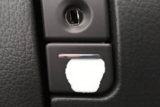
Glove compartment
Parts
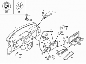
Key block
| Part No. | Notes |
|---|---|
| A2206800284 (left hand drive vehicles) | Replaced by: A2206800784 |
| A2206800784 (left hand drive vehicles) | |
| A2206800384 (right hand drive vehicles) | Replaced by: A2206800884 |
| A2206800884 (right hand drive vehicles) |
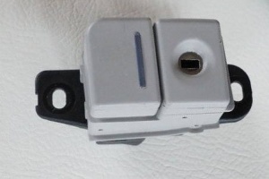
Lock cylinder
| Part No. | Notes |
|---|---|
| A2206890001 | State lock number when ordering; Theft relevant part; Replaced by: A2206890101 |
| A2206890101 | State lock number when ordering; Theft relevant part |
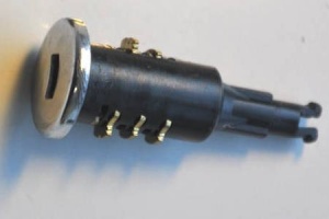
Cap
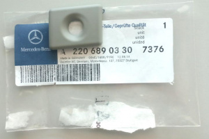
| Part No. | Notes |
|---|---|
| A2206890030 (left hand drive vehicles) | To Date: 01/09/2002 |
| A2206890330 (left hand drive vehicles) | From Date: 30/09/2002 |
| A2206890130 (right hand drive vehicles) | To Date: 01/09/2002 |
| A2206890430 (right hand drive vehicles) | From Date: 30/09/2002 |
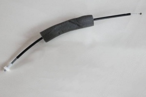
Cable
Part No. A0009964672.
Removing and installing glove compartment
|
|
|
|
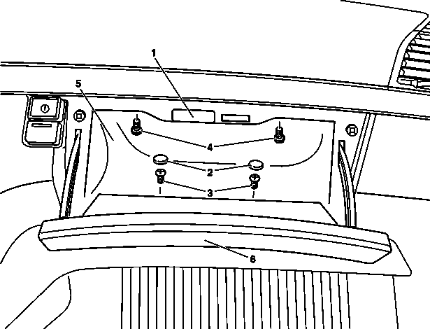
- Open glove compartment lid (6)
- Unclip glove compartment lamp (1) and disconnect connector
- Remove plugs (2)
- Unscrew screws (3)
- Unscrew screws (4)
- Pull glove compartment (5) completely out of instrument panel
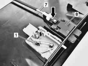
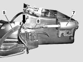
- Unhook control cable (7) on lock (8) on glove compartment (5). When unhooking the control cable (7) ensure that the slider (arrow) is not pulled out of the lock (8).
- Install in opposite order
Removing and installing glove compartment lid
|
|
|
|
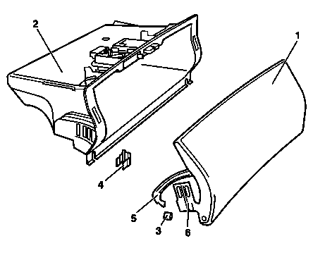
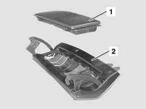
- Remove glove compartment (2)
- Unclip damping strip (8) on right from strap (5), (arrow) on glove compartment lid (1)
- Remove rubber stops (3) from strap (5)
- Pull expanding anchor (4) out of glove compartment (2). Pull expanding anchor out of glove compartment from inside.
- Remove glove compartment lid (1) together with hinges (6) uniformly downward
- Install in opposite order
- Adjust glove compartment lid
Disassembling and reassembling glove compartment lid
|
|
Adjusting glove compartment lid
|
|
|
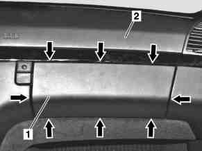
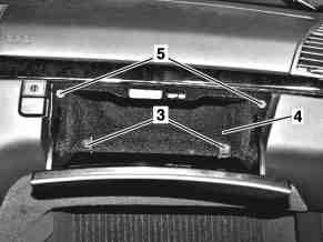
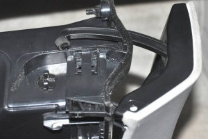
During entire operation pay attention to uniform transition and gap all the way around (arrows) on the glove compartment lid (1) in relation to the instrument panel (2).
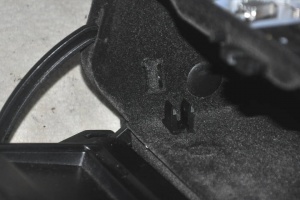
- Pull out both expanding anchors (3) from glove compartment lid (4) with small screwdriver
- Close glove compartment lid (1), adjust horizontal gap and transitions (arrows). Glove compartment lid (1) can be adjusted increment for increment on the hinge.
- Carefully open glove compartment lid (1) and press in expanding anchors (3)
- Check gap width at side, adjust.
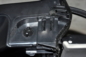
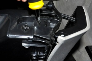
- Differences in the gap width can be corrected slightly by loosening the mounting screws (4 each) for the glove compartment (4) and then moving.
- Check transition from glove compartment lid (1) to instrument panel (2), adjust. Adjustment is possible by screwing the two stop screws (5) in or out.
- Check for easy motion and proper function
 |
 |
 |
 |
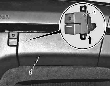
Removing and installing key block on glove compartment lid
|
|
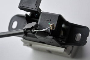
- Remove glove compartment
- Unscrew mounting screws for key block (1). Key block (1) is screwed onto instrument panel (2) from rear (two Torx 20 screws).
- Remove key block (1) to side
- Unhook control cable from eye (arrow) on key block (1). Installation: Check function of control cable, adjust with knurled nut if necessary.
- Install in opposite order
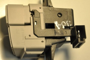
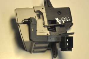
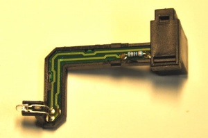
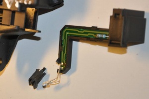
Removing and installing light module on key block
Before pulling out LED module, make sure to unclip the retaining clip on the head of LED, otherwise plastic head will get broken.
 |
 |
 |
 |
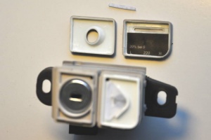
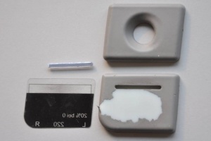
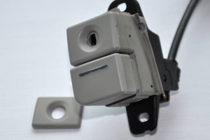
Removing plastic caps on key block
Plastic caps are not glued and can be easily detached.
 |
 |
 |
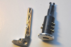
Removing and installing lock cylinder on key block
 |
 |
 |
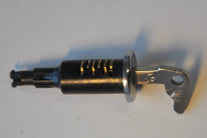 |
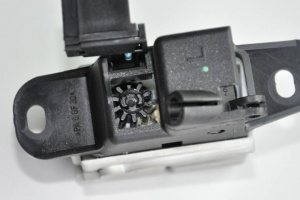
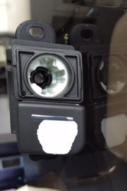
- Remove plastic cap attached to the key block over lock cylinder
- Press together lock cylinder retaining clips on the back of the key block and push lock cylinder out
- To reinstall insert key into lock cylinder and push lock cylinder back in
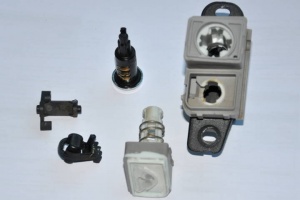
Removing glove box release button
Glove box release button can be completely removed from the key block. However, it is hard to do it without causing some damage to button retaining clips (see below).
Fixing worn glove box release buttons
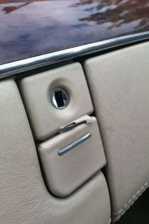
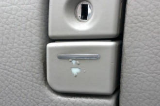
Very popular problem with plastic caps used on glove box release button is them to get worn out. The color layer after years peals off leaving the plastic caps visible.
|
|
Worn cap over the lock cylinder can be replaced by ordering the cap for around EUR 6 (part number A2206890?30 + color code).
To replace worn cap over the release button the whole key block has to be replaced for around EUR 100 (part number A2206800?84 + color code). The lock cylinder must be removed and transferred to the new part.
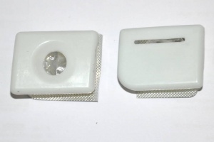
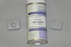
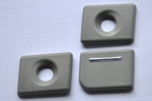
Alternatively, the plastic caps can be painted as shown below.
 |
 |
 |
 |
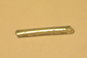
The plastic chrome insert on the release button cap has worn-out and would require painting also.
