Distronic: Difference between revisions
Ricebubbles (talk | contribs) (→STEP 05 Add DTR to ME 2.8 SFI: Updated) |
(Changes in DIstronic activation metod after 2004-06-01, added Part numbers after 2004-06-01) |
||
| (35 intermediate revisions by 2 users not shown) | |||
| Line 84: | Line 84: | ||
[[File:Distronic Retrofit 011.jpg|600px|center]] | [[File:Distronic Retrofit 011.jpg|600px|center]] | ||
===Distronic Input and Output Signals=== | ===Distronic Network and Input and Output Signals=== | ||
[[File:20200319 DTR Network.JPG|600px|center]] | |||
[[File:Distronic Retrofit 012.jpg|600px|center]] | [[File:Distronic Retrofit 012.jpg|600px|center]] | ||
[[File:Distronic Retrofit 013.jpg|600px|center]] | [[File:Distronic Retrofit 013.jpg|600px|center]] | ||
| Line 212: | Line 213: | ||
===Distronic Part Numbers - W220 after 2004-06-01=== | ===Distronic Part Numbers - W220 after 2004-06-01=== | ||
Parts for Distronic after 2004-06-01 are a bit different. Main difference is radar unit witch is no longer two-box, instead is only radar and module in one. Wiring harness is also different, it just contains fuse holder, ground connection and CAN-H and CAN-L connection. Grill and switches inside car are the same as before. | |||
Parts that has been changed: | |||
Wiring harness - A2205405930 | |||
Radar and module unit - A2205454232 | |||
==Availability - Distronic Parts== | ==Availability - Distronic Parts== | ||
| Line 281: | Line 289: | ||
[[File:W220 Installing Distronic Major Wiring Harness 02.jpg||500px|center|thumb|none|]] | [[File:W220 Installing Distronic Major Wiring Harness 02.jpg||500px|center|thumb|none|]] | ||
* Remove the Front Right Engine Bay Fusebox (F1/1). TIP: The Fusebox can be placed to one side to allow good access for routing the Distronic cable throughh the firewall into the FR foot well. | * Remove the Front Right Engine Bay Fusebox (F1/1). TIP: The Fusebox can be placed to one side to allow good access for routing the Distronic cable throughh the firewall into the FR foot well. | ||
* Remove the FR floor carpet. TIP: | * Remove the FR floor carpet. TIP: On a RHD drive car remove the accelerator pedal first. | ||
* Using a plastic rod or stiff wire with the end of the Distronic cable temporarily taped to it, push through the opening into the FR foot well. | * Using a plastic rod or stiff wire with the end of the Distronic cable temporarily taped to it, push through the opening into the FR foot well. | ||
* Pull the wiring loom through to the inside of the vehicle | * Pull the wiring loom through to the inside of the vehicle. | ||
* Install Distronic fuse carrier into the empty position f36 in the the Front Right Engine Bay Fusebox (F1/1). TIP: f36 is the third fuse counting from the rear. | * Install Distronic fuse carrier into the empty position f36 in the the Front Right Engine Bay Fusebox (F1/1). TIP: f36 is the third fuse counting from the rear. | ||
[[File:W220 Installing Distronic Fuse.jpg||500px|center|thumb|none|]] | [[File:W220 Installing Distronic Fuse.jpg||500px|center|thumb|none|]] | ||
* On LHD vehicles, connect the earth lead to the earth point in the FR | * On LHD vehicles, connect the earth lead to the earth point in the FR foot-well. On RHD vehicles either connect the earth lead to the earth point in the FR foot-well or extend the earth wire (brown) by about 1.5m so that it will reach the FL foot-well earth point. | ||
* On LHD vehicles install the Distronic Control Module (N63/1) on the FR (passenger) aluminium | * On LHD vehicles install the Distronic Control Module (N63/1) on the FR (passenger) aluminium floor plate and connect the loom. TIP: For RHD vehicles, skip this step. | ||
* Remove the FL floor carpet. | * Remove the FL floor carpet. | ||
* Using a plastic rod or stiff wire with the end of the Distronic cable temporarily taped to it, push through behind the COMAND to the FL foot well | * Using a plastic rod or stiff wire with the end of the Distronic cable temporarily taped to it, push through behind the COMAND to the FL foot-well | ||
* On RHD vehicles install the Distronic Control Module (N63/1) on the FL (passenger) aluminium | * On RHD vehicles install the Distronic Control Module (N63/1) on the FL (passenger) aluminium floor plate and connect the loom. TIP: You may need to re position the control module on the aluminium floor plate rather than use the OEM mounting holes, in order to allow the Distronic coax cable to reach the appropriate connector. | ||
[[File:W220 Installing Distronic Control Module.JPG||500px|center|thumb|none|]] | [[File:W220 Installing Distronic Control Module.JPG||500px|center|thumb|none|DTR ecu in FL (RHD passenger) foot-well and relocated to the left in photo to accommodate a slightly shorter cable length.]] | ||
* Route the remaining Distronic loom to the FL cable ducting in the floor. | * Route the remaining Distronic loom to the FL cable ducting in the floor. | ||
* Connect the Distronic loom twisted pair (green and green/white) to any similar "engine" | * Connect the Distronic loom twisted pair (green and green/white) to any similar "engine" CAN bus twisted pair in the cable duct. TIP: Ensure the green CAN-CL wires are connected together and the green/white CAN-CH wires are twisted together. | ||
* Connect the Distronic loom diagnostic wire (pink) to the blue/white wire on connector X35/66 in FL | [[File:Identifying CAN C Engine Bus Twisted Pair.JPG||500px|center|thumb|none|CAN-C "engine" bus twisted pair (green and green/white) in Cable Duct in FL (RHD passenger) foot-well.]] | ||
* Take vehicle to a Mercedes dealer for coding and most importantly for Distronic sensor alignment. TIP: If the car is a pre 2004-05-31 model the coding can be done using a Star DAS. | * Connect the Distronic loom diagnostic wire (pink) to the blue/white wire on connector X35/66 in FL foot-well cable ducting. TIP: X35/66 is the large black connector. TIP: The diagnostic wire X35/66 pin 8 (blue/white) goes to the OBDII port X11/4 pin 15 which is used by Star DAS to communicate with the DTR. | ||
* Take vehicle to a Mercedes dealer for coding and most importantly for Distronic sensor alignment. TIP: If the car is a pre 2004-05-31 model the coding can be done using a Star DAS with Developer Mode. | |||
TIP: Apart from the alignment of the Distronic sensor the vehicle will have to be coded to activate/enable the Distronic: | TIP: Apart from the alignment of the Distronic sensor the vehicle will have to be coded to activate/enable the Distronic: | ||
* Drive | * Drive > ME (Engine Management): Either have Option 219 added to the datacard and SCN code the Engine Management system (best), or using Star Diagnosis with 'Factory Mode or Developer key' and enable Distronic/DTR. (NB. if you don't have option 219 added to the datacard and the engine management system is SCN coded in the future, then not only will Distronic not work, but there will be an ESP error and various other issues). | ||
* Body | * Body > System Diagnosis: Enable DTR/Distronic. (This is for diagnosis purposes). | ||
* Body | * Body > CGW (Central Gateway): Enable DTR/Distronic. (This tells the lower control panel and ESP the car has Distronic, so once this is done the button for Distronic will light up). | ||
* Info & Communication Systems | * Info & Communication Systems > ICM (Instrument Cluster): Enable DTR/Distronic. (This enables the menu on the cluster). | ||
===W220 after 2004-06-01 - Distronic Retrofit=== | ===W220 after 2004-06-01 - Distronic Retrofit=== | ||
After 2004-06-01 SCN Coding has been introduced, which close the way to use only DAS. To change coding in your car you have to add code 219 to your data card, then perform online SCN coding by dealership or some independent workshops. Rest of modules such as Instrument Cluster, CGW, EZS have to be coded and it can be activated offline by DAS. If you have access to Star Diagnosis you can change variant coding in ECU by Vediamo. (I have tried Vediamo by myself and I changed it successfully). | |||
====Retrofit Method - W220 after 2004-06-01==== | ====Retrofit Method - W220 after 2004-06-01==== | ||
| Line 319: | Line 324: | ||
==Activation/Adaptation/Coding – Distronic (DTR)== | ==Activation/Adaptation/Coding – Distronic (DTR)== | ||
Vehicle | Vehicle control unit Activation/Adaptation/Coding/Programming is necessary after: | ||
*Replacement of DTR control module (N63/1) | *Replacement of DTR control module (N63/1) | ||
*Replacement of steering angle sensor (N49) | *Replacement of steering angle sensor (N49) | ||
| Line 326: | Line 331: | ||
*Exchange or repair of chassis components including setting wheel toe. | *Exchange or repair of chassis components including setting wheel toe. | ||
The | The N63/1 Distronic (DTR) ecu connects directly to these components; | ||
* B29 Distronic Radar Sensor | |||
*Radar Sensor | * K40/7 Right front fuse and relay module (terminal 87 voltage supply) | ||
* | * X11/4 Data link connector | ||
* | |||
The N63/1 Distronic (DTR) ecu connects via the CAN-C engine bus to these components; | |||
* N73 Control gateway gateway (CGW) | |||
* A1 Instrument control module (ICM) | |||
* N80 Steering column module (SCM-MRM) | |||
* N73 Electronic ignition switch (EZS/ZGW) | |||
* N15/3 Electronic transmission control (ETC) | |||
* N3/10 Engine management electronics (ME-SFI) | |||
* N47-5 Electronic Stability Program (ESP), Speed Sensitive Power Steering(SPS), Brake Assist (BAS) | |||
Distronic requires control unit adaptation in; | The N63/1 Distronic (DTR) ecu connects via the CAN-B interior bus via Control gateway (CGW) ecu which communicates to; | ||
*EZS | * N72/1 Upper control panel (UCP) and then the S46/8 Distronic Switch Block in centre console. | ||
* | * N10/8 Rear SAM control unit (REAR SAM) | ||
*UCP | * N28/1 Trailer recognition control unit (special equipment) | ||
* | |||
* | The N63/1 Distronic (DTR) ecu connects indirectly to these components; | ||
* N49 Steering Angle Sensor | |||
* S40/4 Cruise Control Switch | |||
* S46/8 Console Switches | |||
* A7/7y1 BAS solenoid valve | |||
Distronic requires control unit adaptation in these ecu's and preferably in this order; | |||
* Central gate way (CGW) | |||
* Electronic ignition switch (EZS) | |||
* Instrument cluster with maintenance display (ICM) | |||
* Upper control panel (UCP) | |||
* Motor electronics (ME-SFI) | |||
* Distronic (DTR) | |||
TIP: Be aware of the difference between Control unit adaptations and Control unit adaptations done in Development Mode. The former allows access to the main codes for a vehicle and should be used in most situations. The latter allows access to these main codes plus a lot of normally hidden codes and should only be used by experienced persons. | TIP: Be aware of the difference between Control unit adaptations and Control unit adaptations done in Development Mode. The former allows access to the main codes for a vehicle and should be used in most situations. The latter allows access to these main codes plus a lot of normally hidden codes and should only be used by experienced persons. | ||
BE WARNED: Activation requires specialized expertise. Distronic activation with Star Diagnosis System (SDS) off-line is not possible for vehicles manufactured after 2004-06-01. ESP SPS BAS errors will result. These cars require coding using the SCN system via an on-line SDS. On these later model cars if you don't have option 219 added to the datacard and the engine management system | BE WARNED: Activation requires specialized expertise. Distronic activation with Star Diagnosis System (SDS) off-line is not possible for vehicles manufactured after 2004-06-01. ESP SPS BAS errors will result. These cars require coding using the SCN system via an on-line SDS. On these later model cars if you don't have option 219 added to the datacard and the engine management system upgraded to the latest version, then the Distronic will not work and an ESP error will alternate with SRS warnings on the instrument panel. Even if the vehicle is manufactured before 2004-06-01 similar ESP SPS BAS error messages may appear on the Instrument Cluster. The ME ecu should be updated to the latest version before undertaking this project. | ||
TIP: The following steps and associated photographs may differ for different years and models of M-B cars. | TIP: The following steps and associated photographs may differ for different years and models of M-B cars. | ||
TIP: Each Step has a summary and a detailed description. The summary is useful as a hard copy and can be used to guide you through the steps. It is recommended that you print out the | TIP: Each Step has a summary and a detailed description. The summary is useful as a hard copy and can be used to guide you through the steps. It is recommended that you print out the summary for each step before starting. | ||
| Line 362: | Line 378: | ||
The method for adapting the Distronic (DTR) is very similar to that used for changing the top speed limit (factory coded setting Vmax) of an AMG. BenzWorld member Bayhas Kana has posted a video [https://youtu.be/9xD9d1uRRbQ] on this topic and it is a useful guide for retrofitting the DTR as far as the coding is concerned. Also see; [http://www.benzworld.org/forums/r230...l#post12226361]. | The method for adapting the Distronic (DTR) is very similar to that used for changing the top speed limit (factory coded setting Vmax) of an AMG. BenzWorld member Bayhas Kana has posted a video [https://youtu.be/9xD9d1uRRbQ] on this topic and it is a useful guide for retrofitting the DTR as far as the coding is concerned. Also see; [http://www.benzworld.org/forums/r230...l#post12226361]. | ||
The | '''Note''': The author prefers to use a list of steps rather than a video as a tutorial because it can be printed and each step ticked off as they are completed. | ||
'''Update 20200314:''' Success at last! The author, BenzWorld member 'ricebubbles' can now report the successful installation and coding of a Distronic in a 2003 Update W220 S500L. The project took 18 months and a lot of agony reverse engineering the various Variant codes, mostly in German, using an '''off-line''' Star Diagnosis System. The trick was to investigate every possible option for every electronic control unit, looking for anything possibly related to Cruise Control (most common cruise control fitted), Speedtronic (speed limiter) and Distronic (radar cruise control). The secret to the author's success was to find the Variant code in the CGW ecu for "CAN-C: Abstandsassistent" [=CAN-C: Distance Assistant] which was coded "nicht vorhanden" [=not available] and once this was changed to "vorhanden" [=available], along with the other more obvious changes shown below, the system worked perfectly. | |||
The author used to think that the Speed Limiter was the best device in the W220, but now having tried Distronic, rates Distronic equal best with the Speed Limiter. It is the best modification done to his W220. | |||
The following steps have been edited to reflect the successful procedure. Be aware that other cars may require different or additional steps. | |||
The steps required for activating Distronic or Distance Tracking Radar (DTR) using Star Diagnosis System (SDS) with 'Factory Mode or Developer key' are as follows. | |||
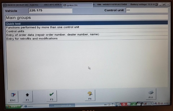
* Start XENTRY | |||
* Configure COM Port from 19,200 to 9,600 bps. | |||
* Add Distronic in control unit CGW (Central gate way) | |||
* Confirm Distronic in control unit CGW (Central gate way) | |||
* Enable Distronic in control unit EZS (Electronic ignition switch) | |||
* Enable Distronic in control unit ICM (Instrument cluster with maintenance display) | |||
* Distronic and control unit UCP (Upper control panel) | |||
* Unlock control unit ME-SFI 2.8 (Motor electronics) for Programming | |||
* Enable ART in ME (Using Implizite Kodierung [Implicit Coding]) | |||
* Reset/Initialize control unit DTR (Distronic) | |||
* Clear all fault codes | |||
''' | ====STEP 00 MUST READ Preliminary==== | ||
SDS XENTRY is a real pain to use when changing the Motor Electronic (ME) ecu, especially the ecu unlock step, which nearly always took many attempts (using the same technique) before it would unlock. | |||
It also helps to understand that there are two main modes of operation of XENTRY. The simplest, accessed via each ecu and '''Control unit adaptations''' return the Variant codings and the set option in English. This is how to open the ME ecu in this mode; | |||
* ME Variant coding via Control unit groups > Drive > ME-SFI 2.8 > Control unit adaptations > Variant Coding > Display of coding data > Coding. | |||
The second mode, which is extremely powerful and if not used carefully, slowly and with considerable thought before each step, can end up "bricking" the car, ie rendering it useless, so be warned. It is called '''Developer mode''' and returns the Variant codings and the set and available options in German, so having a translation available before starting is essential. It is possible to create a reasonable translation by reading all the possible codes in the normal/simple mode (in English) and repeating in Developer Mode (in German) and comparing the two, line by line. This is how to open the ME ecu in this Developer Mode; | |||
* Control unit groups > Drive > ME-SFI 2.8 > Development data > Control unit adaptations > Read coding and/or transfer download data to a new control unit > Control unit adaptations (Variant Coding) > Implizite Kodierung | |||
A warning about Explizite Kodierung. As far as the author can ascertain, Explizite Kodierung seems to be a quick way for the factory to set '''multiple''' variant codes for a particular vehicle, with just a few mouse clicks in SDS. The same codes may be set, one by one, using Implizite Kodeirung, in a more controlled fashion. It took the author several days to recover after using Explizite Kodierung to change the ME ecu to what he thought was the correct vehicle. As well as making a couple of required changes, the SDS also changed a heap of other parameters and upset the vehicle completely. For example, the tyre settings changed to some weird specifications, which affected the Speedometer, Cruise Control and Speed Limiter (no Distronic at this stage) which were all different and out compared to a GPS speed indication by a factor of 1.9. TIP: Before you start on this or a similar project, make sure you have created a full backup record of every setting for every ecu, just in case something goes wrong. The translation printouts, if they are complete, will help in this regard, but you cannot beat having a photograph of every setting. Fortunately the author found some old photographs from two years before the | |||
Explizite Kodiering mistake, otherwise he would not have been able to recover without a lot of trial and error. | |||
The author found an Internet suggestion that the engine needs to be running and idling, for ME control unit programming to be properly stored and committed, didn't apply in his case. The vehicle MUST be connected to a battery charger though, and the car voltage (as seen on SDS) should not go below 12.6V. | |||
TIP: Enthusiasts who have attempted changing coding using SDS seem to have discovered a possible quirk/bug in the SDS software; | |||
SDS appears to read the existing ecu settings, then when the screen appears, the fields are blank (actually "- - -"), and SDS states that one or more setting is invalid. This quirk is mostly overcome by first using "Read coding and/or transfer data to a new control unit" just to read the data, (but do not transfer the read codes to a "new control unit" by pressing the "NO F4" button at the appropriate time. All going well, SDS will actually show the current values for the ecu. The author found in the EIS (EZS) ecu that he coudn't get rid of the blanks and went ahead with the required changes any way, leaving most of the fields blank, and it didn't seem to matter if the fields as read/observed were left blank. The required changes were successfully made. | |||
====STEP 01 Starting XENTRY==== | ====STEP 01 Starting XENTRY==== | ||
Connect | Connect SDS (must have Developer Mode enabled) to vehicle | ||
# Open XENTRY Diagnostics. | # Open XENTRY Diagnostics. | ||
| Line 395: | Line 445: | ||
====STEP 02 Add DTR to CGW==== | ====STEP 02 Add DTR to CGW==== | ||
Updated | Updated 20200314 | ||
The following steps may be used to add Distronic (DTR) availability to the Central Gateway (CGW) electronic control module for a M-B W220 manufactured before 2004-05-31. | The following steps may be used to add Distronic (DTR) availability to the Central Gateway (CGW) electronic control module for a M-B W220 manufactured before 2004-05-31. This tells the UCP and Electronic Stability Programme (ESP) that the car has Distronic, so once this is done the button for Distronic will light up. | ||
In summary: | In summary: | ||
| Line 415: | Line 465: | ||
* Control unit adaptations (Variant coding) | * Control unit adaptations (Variant coding) | ||
* Globale Variantencodierung [Global variant coding] | * Globale Variantencodierung [Global variant coding] | ||
* Abstandsregeltempomat [Adaptive cruise control] | ** Abstandsregeltempomat [Adaptive cruise control] | ||
* Change nicht vorhanden [not available] to vorhanden [available] | *** Change nicht vorhanden [not available] to vorhanden [available] | ||
** CAN-C: Abstandsassistent [CAN-C: Distance Assistant] | |||
*** Change nicht vorhanden [not available] to vorhanden [available] | |||
* Is the coding to be transferred to the control unit? | * Is the coding to be transferred to the control unit? | ||
* YES F3 | * YES F3 | ||
| Line 451: | Line 503: | ||
# Highlight '''Control unit adaptations''' and click '''F3'''. | # Highlight '''Control unit adaptations''' and click '''F3'''. | ||
# Observe the page Control unit '''CGW''' with title '''Control unit adaptations'''. | # Observe the page Control unit '''CGW''' with title '''Control unit adaptations'''. | ||
# Highlight Read coding and/or transfer download data to a new control unit | # Highlight '''Read coding and/or transfer download data to a new control unit''' | ||
# Observe the page Control unit CGW with title Control unit adaptations. | # Click '''F3'''. | ||
# Observe the page Control unit CGW with title '''Control unit adaptations'''. | |||
# Observe the Warning; When replacing different control module versions (e.g. Q1 for Q2), wrong coding can occur. For this reason the code settings must be check (sic) under ‘Control unit adaptations (Variant coding)’. | # Observe the Warning; When replacing different control module versions (e.g. Q1 for Q2), wrong coding can occur. For this reason the code settings must be check (sic) under ‘Control unit adaptations (Variant coding)’. | ||
# Click OK to go forward. | # Click '''OK''' to go forward. | ||
# Observe the page Control unit CGW with statement | # Observe the page Control unit CGW with statement “'''The coding is being read, please wait.'''” | ||
# Observe the page Control unit EZS with statement: | # Observe the page Control unit EZS with statement: “'''Coding has been read.'''” | ||
# Observe statement: | # Observe statement: “'''Switch off ignition.'''” | ||
# Switch off ignition and check SDS screen. Wait until observe statement: “Switch on ignition.” | # Switch off ignition and check SDS screen. '''Wait until observe statement: “Switch on ignition.”''' | ||
# Observe the page Control unit CGW with statement Replace the old control unit with the new control unit. | # Observe the page Control unit CGW with statement '''Replace the old control unit with the new control unit.''' | ||
# Observe statement: “Switch on ignition.” | # Observe statement: “Switch on ignition.” | ||
# Switch on ignition | # '''Switch on ignition''' | ||
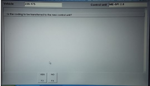
# Read the question, | # Read the question, “'''Is the coding to be transferred to the new control unit?'''” | ||
# Click on NO F4 (See TIP at beginning of this step to understand why this is done.) | # Click on '''NO F4''' (See TIP at beginning of this step to understand why this is done.) | ||
# Observe the page Control unit CGW with title Control unit adaptations | # Observe the page Control unit CGW with title '''Control unit adaptations''' | ||
# Highlight '''Control unit adaptations (Variant coding)'''. | # Highlight '''Control unit adaptations (Variant coding)'''. | ||
#: '''Note''': This is the command for manual coding of different features in the vehicle. | #: '''Note''': This is the command for manual coding of different features in the vehicle. | ||
| Line 471: | Line 524: | ||
# Highlight Globale Variantencodierung [Global variant coding], then click '''F3'''. | # Highlight Globale Variantencodierung [Global variant coding], then click '''F3'''. | ||
# Observe “The coding is being read.” | # Observe “The coding is being read.” | ||
# Observe page Control unit CGW with title Globale Variantencodierung [Global variant coding] | # Observe page Control unit CGW with title '''Globale Variantencodierung''' [Global variant coding] | ||
# Scroll up or down the page to see Abstandsregeltempomat [Adaptive cruise control] | ## Scroll up or down the page to see '''Abstandsregeltempomat''' [Adaptive cruise control] | ||
# Observe option nicht vorhanden [not available] | ### Observe option '''nicht vorhanden''' [not available] | ||
# Use drop down menu to select vorhanden [available] | ### Use drop down menu to select '''vorhanden''' [available] | ||
# Select F3 to go forward | ## Scroll up or down the page to see '''CAN-C: Abstandsassistent''' [CAN-C: Distance Assistant] | ||
# Observe statement | ### Observe option '''nicht vorhanden''' [not available] | ||
# Select YES F3 | ### Use drop down menu to select '''vorhanden''' [available] | ||
# Observe | # Select '''F3''' to go forward | ||
# Observe | # Observe statement “'''Is the coding to be transferred to the control unit?'''” | ||
# Select '''YES F3''' | |||
# Observe “'''The coding is being carried out'''.” | |||
# Observe “'''The coding has been carried out.'''” | |||
# Now back out gracefully. | # Now back out gracefully. | ||
# Observe the page Control unit '''---''' with title '''Control unit groups'''. | # Observe the page Control unit '''---''' with title '''Control unit groups'''. | ||
| Line 485: | Line 541: | ||
==== STEP 03 Confirm Distronic in CGW ==== | ==== STEP 03 Confirm Distronic in CGW ==== | ||
Updated | Updated 20200314 | ||
The following steps may be used to confirm Distronic (DTR) availability to the Central Gateway (CGW) ecu for M-B W220 manufactured before 2004-05-31. | The following steps may be used to confirm Distronic (DTR) availability to the Central Gateway (CGW) ecu for M-B W220 manufactured before 2004-05-31. It is not really necessary to perform this step, but can give you reassurance that everything is going well. | ||
In summary: | In summary: | ||
| Line 495: | Line 551: | ||
* CGW – Central gateway | * CGW – Central gateway | ||
* Clear any faults or events stored in memory | * Clear any faults or events stored in memory | ||
* Control unit adaptations | |||
* Read coding and change if necessary. | * Read coding and change if necessary. | ||
* Distronic | * Distronic | ||
| Line 526: | Line 583: | ||
====STEP 04 Add DTR to EZS==== | ====STEP 04 Add DTR to EZS==== | ||
Updated | Updated 20200314 | ||
The following steps may be used to add Distronic (DTR) availability to the Electronic ignition switch (EZS or ZGW) electronic control module for a M-B W220 manufactured before 2004-05-31. | The following steps may be used to add Distronic (DTR) availability to the Electronic ignition switch (EZS or ZGW) electronic control module for a M-B W220 manufactured before 2004-05-31. | ||
TIP: Enthusiasts who have attempted this step seem to have discovered a possible quirk/bug in the SDS software; | |||
* SDS appears to read the existing ecu settings, then when the screen appears, the fields are blank, and SDS states that one or more setting is invalid. This quirk is overcome by first using "Read coding and/or transfer data to a new control unit" just to read the data, then SDS will actually show the current values for the ecu. It doesn’t seem to matter if the fields as read/observed are blank. | |||
In summary: | In summary: | ||
| Line 536: | Line 596: | ||
* EZS – Electronic ignition switch ELCODE (DAS 3) | * EZS – Electronic ignition switch ELCODE (DAS 3) | ||
* Clear any faults or events stored in memory | * Clear any faults or events stored in memory | ||
* Development data | |||
* Control unit adaptations | * Control unit adaptations | ||
* Main menu of control module EZS3 | * Main menu of control module EZS3 | ||
* Read coding and/or transfer download data to a new control unit. | |||
* Wait because it takes a long time. | |||
* Read coding and/or transfer download data to a new control unit. | |||
* Switch off ignition | |||
* Switch on ignition | |||
* Is the coding to be transferred to the new control unit? | |||
* NO F4 | |||
* Control unit adaptations | * Control unit adaptations | ||
Control unit adaptations (Variant coding) | * Control unit adaptations (Variant coding) | ||
* Varcode_Description | * Varcode_Description | ||
* Abstandregeltempomat [Adaptive cruise control] | * Abstandregeltempomat [Adaptive cruise control] | ||
| Line 578: | Line 645: | ||
# Observe the page Control unit '''EZS''' with title '''Control unit adaptations'''. | # Observe the page Control unit '''EZS''' with title '''Control unit adaptations'''. | ||
# Highlight Read coding and/or transfer download data to a new control unit and click '''F3''' | # Highlight Read coding and/or transfer download data to a new control unit and click '''F3''' | ||
# Observe the page Control unit EZS with title Control unit adaptations. | # Observe the page Control unit EZS with title '''Control unit adaptations'''. | ||
# Observe the Warning; When replacing different control module versions (e.g. Q1 for Q2), wrong coding can occur. For this reason the code settings must be check (sic) under ‘Control unit adaptations (Variant coding)’. | # Observe the Warning; When replacing different control module versions (e.g. Q1 for Q2), wrong coding can occur. For this reason the code settings must be check (sic) under ‘Control unit adaptations (Variant coding)’. | ||
# Click OK to go forward. | # Click '''OK''' to go forward. | ||
# Observe the page Control unit EZS with statement | # Observe the page Control unit EZS with statement “'''The coding is being read, please wait.” | ||
# Observe the page Control unit EZS with statement: | # Observe the page Control unit EZS with statement: “'''Coding has been read.'''” | ||
# Observe statement: | # Observe statement: “'''Switch off ignition.'''” | ||
# Switch off ignition and check SDS screen. Wait until observe statement: “Switch on ignition.” | # '''Switch off ignition''' and check SDS screen. '''Wait''' until observe statement: “Switch on ignition.” | ||
# Observe the page Control unit EZS with statement Replace the old control unit with the new control unit. | # Observe the page Control unit EZS with statement '''Replace the old control unit with the new control unit.''' | ||
# Observe statement: “Switch on ignition.” | # Observe statement: “Switch on ignition.” | ||
# Switch on ignition. | # '''Switch on ignition.''' | ||
# Read the question, | # Read the question, “'''Is the coding to be transferred to the new control unit?'''” | ||
# Click on NO F4. (See TIP to understand why this is done.) | # Click on '''NO F4'''. (See TIP to understand why this is done.) | ||
# Observe the page Control unit EZS with title Control unit adaptations | # Observe the page Control unit EZS with title '''Control unit adaptations''' | ||
# Highlight '''Control unit adaptations (Variant coding)'''. | # Highlight '''Control unit adaptations (Variant coding)'''. | ||
#: '''Note''': This is the command for manual coding of different features in the vehicle. | #: '''Note''': This is the command for manual coding of different features in the vehicle. | ||
| Line 605: | Line 672: | ||
# Click on '''YES F3'''. | # Click on '''YES F3'''. | ||
# Observe the page '''Control unit EZS''' with title '''Varcode_Description'''. | # Observe the page '''Control unit EZS''' with title '''Varcode_Description'''. | ||
# Observe statement; The coding has been carried out. | # Observe statement; '''The coding has been carried out.''' | ||
# Click '''F2''' to forward. | # Click '''F2''' to forward. | ||
# Now back out gracefully. | # Now back out gracefully. | ||
| Line 612: | Line 679: | ||
====STEP 05 Add DTR to ICM==== | ====STEP 05 Add DTR to ICM==== | ||
Updated | Updated 20200314 | ||
The following steps may be used to add Distronic (DTR) availability to the Instrument Cluster (ICM) electronic control module for a M-B W220 manufactured before 2004-05-31. | The following steps may be used to add Distronic (DTR) availability to the Instrument Cluster (ICM) electronic control module for a M-B W220 manufactured before 2004-05-31. | ||
| Line 657: | Line 724: | ||
# Observe the page Control unit '''ICM''' with title '''Special equipment'''. | # Observe the page Control unit '''ICM''' with title '''Special equipment'''. | ||
# Read the DTR Distronic Notes on coding. | # Read the DTR Distronic Notes on coding. | ||
# Use the drop down arrow to view the DTR Distronic field options and highlight '''PRESENT''' | # Use the drop down arrow to view the DTR Distronic field options and highlight '''PRESENT''' | ||
# Click '''F3'''. | |||
# Observe the page Control unit '''ICM''' with title '''Special equipment'''. | # Observe the page Control unit '''ICM''' with title '''Special equipment'''. | ||
# Select F5 | # Select '''F5''' “'''write codings'''”. | ||
# Observe the page Control unit ICM with title Special equipment. | # Observe the page Control unit ICM with title '''Special equipment'''. | ||
# Note: | # Note: “'''The coding has been changed.'''” | ||
# Read the question, | # Read the question, “'''Is the coding to be transferred to the control unit?'''” | ||
# Click on YES F3 | # Click on '''YES F3''' | ||
# Read the status, | # Read the status, “'''The coding is being carried out, please wait.'''” | ||
# Read the status, The coding has been carried out. | # Read the status," '''The coding has been carried out.'''" | ||
# Observe the page Control unit ICM with title Variant coding. | # Observe the page Control unit ICM with title Variant coding. | ||
#: Now back out gracefully. | #: Now back out gracefully. | ||
| Line 671: | Line 739: | ||
#: '''This is the starting page for all DTR adaptations.''' | #: '''This is the starting page for all DTR adaptations.''' | ||
====STEP 06 Add DTR to | ====STEP 06 Add DTR to UCP==== | ||
Updated 20200314 | |||
It is not necessary to enable Distronic (DTR) availability in the Upper Control Panel (UCP) ecu for a M-B W220 manufactured before 2004-05-31. Once the UCP and the Upper Control Panel (N72/1) is connected to the Switch block (S46/8) via the Electrical Cable, the switch and distance potentiometer should work. This can be verified using Star Diagnosis System in the normal way. | |||
====STEP 07 Unlock ME for Programming==== | |||
Updated 20200317 | |||
The following steps may be used to unlock the ME 2.8 SFI electronic control module ready for programming for a M-B W220 manufactured before 2004-05-31. | |||
TIP: Unlocking the ME ecu '''must''' be done before doing any coding changes to the ME ecu. | |||
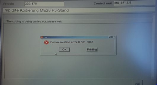
TIP: The ME ecu is particularly difficult to unlock and may require several attempts before you see "Result: Zugriff erlaubt, Funktionen freigegeben" [Access allowed, features enabled]. If you see "Result: Zugriff bereits erlaubt." [Access already allowed.] the ecu may not be unlocked and you will get an error message when proceeding: “Communication error 8.561.6067”. This means the ecu is locked and unavailable for coding so go back and repeat the unlock procedure. | |||
In summary: | |||
* Disconnect battery charger | |||
* Engine on and idling | |||
* Control unit groups | |||
* Drive | |||
* ME-SFI 2.8 – Motor electronics 2.8 | |||
* Main menu of control module ME28 | |||
* Safety notes | |||
* Development data | |||
* Actuations | |||
* Complete index of actuations | |||
* Highlight Steuergerät entriegein (DJ_Zugriffsberechtigung) [Control unit unlocked (DJ_Access * authorization)]. | |||
* F3 to go forward | |||
* F3 Start Action | |||
* Result: Zugriff erlaubt, Funktionen freigegeben [Access allowed, features enabled] | |||
* If you see Result: Zugriff bereits erlaubt. [Access already allowed.] go back and repeat the last 3 or 4 steps. | |||
* Result: Zugriff erlaubt, Funktionen freigegeben [Access allowed, features enabled] | |||
* Back out gracefully | |||
In detail: | |||
# Perform the steps for Starting XENTRY above or continue from the last step. | # Perform the steps for Starting XENTRY above or continue from the last step. | ||
# Observe the page Control unit '''---''' with title '''Control unit groups'''. | # Observe the page Control unit '''---''' with title '''Control unit groups'''. | ||
# Highlight ''' | # Highlight '''Drive''', then click '''F3'''. | ||
# Observe the page Control unit '''---''' with title ''' | # Observe the page Control unit '''---''' with title '''Drive'''. | ||
# Highlight ''' | # Highlight '''ME-SFI 2.8 – Motor electronics 2.8''', the click '''F3'''. | ||
# Observe the page Control unit ''' | # Observe the page Control unit '''---''' with title '''ME-SFI 2.8 – Motor electronics 2.8'''. | ||
# Read the safety notes and click '''F3'''. | |||
# Observe the page Control unit '''ME-SFI 2.8''' with title '''ME-SFI 2.8 – Motor electronics 2.8'''. | |||
#: '''Note''': Before performing any adaptation coding any existing fault codes and event memory records should be erased. | #: '''Note''': Before performing any adaptation coding any existing fault codes and event memory records should be erased. | ||
# | # Observe the page Control unit '''ME-SFI 2.8''' with title '''ME-SFI 2.8 – Motor electronics 2.8'''. | ||
# Highlight '''Development data''' and click '''F3'''. | |||
# Observe the page Control unit '''ME-SFI 2.8''' with title '''Main menu of control module ME28'''. | |||
#: '''Important Note''': The author found this suggestion was not necessary, but if you are experiencing problems, it may help to have the engine running and idling, for ME ECM programming modification to be properly saved and permanently stored. | |||
# Highlight '''Actuations''' and click '''F3'''. | |||
# Observe the page Control unit '''ME-SFI 2.8''' with title '''Actuations'''. | |||
# Highlight '''Complete index of actuations''', then click '''F3'''. | |||
# | # Observe the page Control unit '''ME-SFI 2.8''' with title '''Actuations'''. | ||
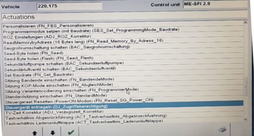
# Scroll up and down the page to see '''Steuergerät entriegein (DJ_Zugriffsberechtigung) [Control unit unlocked (DJ_Access authorization)].''' | |||
# | #: [[File:20200317 Control unit unlocked.JPG|500px|center|thumb|none|Steuergerät entriegein (DJ_Zugriffsberechtigung) [Control unit unlocked (DJ_Access authorization)]]] | ||
# | |||
# Highlight ''' | |||
# Observe the page Control unit ''' | |||
# Highlight ''' | |||
# Observe the page Control unit ''' | |||
# Scroll up and down the page to see | |||
# | |||
# Click '''F3''' to go forward. | # Click '''F3''' to go forward. | ||
# Observe the page Control unit ''' | # Observe the page Control unit '''ME-SFI 2.8''' with title '''Steuergerät entriegein (DJ_Zugriffsberechtigung''' [Control unit unlocked (DJ_Access authorization]. | ||
# | # Observe the Action: F3: Start. | ||
# | # Click '''F3''' to confirm unlocking of the ME 2.8 SFI electronic control module ready for programming. | ||
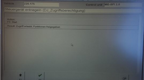
# When the request to unlock the ME 2.8 SFI ECU has worked you will see; '''Result: Zugriff erlaubt, Funktionen freigegeben''' [Access allowed, features enabled]. | |||
#: [[File:20200317 Access allowed, features enabled.JPG|500px|center|thumb|none|Zugriff erlaubt, Funktionen freigegeben [Access allowed, features enabled]]] | |||
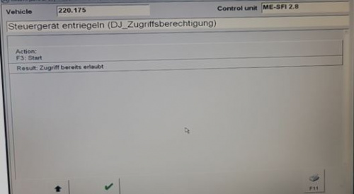
# If you see '''Result: Zugriff bereits erlaubt'''. [Access already allowed.] | |||
#: [[File:20200317 Access already allowed.JPG|500px|center|thumb|none|Zugriff bereits erlaubt. [Access already allowed.]]] | |||
# And then when proceeding see the error message: “'''Communication error 8.561.6067'''” . | |||
#: [[File:20200317 Communication error 8.561.6067.JPG|500px|center|thumb|none|Communication error 8.561.6067]] | |||
#: | # It means the ecu is still '''locked and unavailable for coding'''. Go back to the start and repeat the steps. | ||
# | #:TIP: Experience has shown that you may have to repeat the ME ecu unlock procedure from the beginning several times to get it to work properly. | ||
## | #:TIP: If that doesn't work,it sometimes helps to read the Variant codings first using ''Control unit groups > Drive > ME-SFI 2.8 > Development data > Control unit adaptations > Read coding and/or transfer download data to a new control unit > F4 > Control unit adaptations (Variant Coding) > Implizite Kodierung.'' | ||
# | # Then go back to the start and repeat the steps. | ||
# | # When the ME ecu unlocking is successful, observe the statement: '''Result: Zugriff erlaubt, Funktionen freigegeben''' [Access allowed, features enabled]. | ||
#: [[File:20200317 Access allowed, features enabled.JPG|500px|center|thumb|none|Zugriff erlaubt, Funktionen freigegeben [Access allowed, features enabled]]] | |||
# | # Now back out gracefully. | ||
# | # Observe the page Control unit '''---''' with title '''Drive'''. | ||
# | |||
# | |||
## | |||
# | |||
#: '''This is the starting page for all DTR adaptations.''' | #: '''This is the starting page for all DTR adaptations.''' | ||
====STEP | ====STEP 08 Enable ART in ME (Using Implizite Kodierung [Implicit Coding])==== | ||
The following steps may be used to | Updated 20200317 | ||
The following steps may be used to change the coding option in the ME ecu from Cruise Control to AbstandsRegelTempomat (ART) [Distance rule cruise control] for a M-B W220 manufactured before 2004-05-31. | |||
TIP: Unlocking the ME ecu '''must''' be done before doing any coding changes to the ME ecu. | |||
TIP: The ME ecu is particularly difficult to unlock and may require several attempts before you see "Result: Zugriff erlaubt, Funktionen freigegeben" [Access allowed, features enabled]. If you see "Result: Zugriff bereits erlaubt." [Access already allowed.] the ecu may not be unlocked and you will get an error message when proceeding: “Communication error 8.561.6067”. This means the ecu is locked and unavailable for coding so go back and repeat the unlock procedure. | |||
'''BE WARNED:''' Do not use Explizite Kodierung for this project. Explizite Kodierung [=Explicit coding] is as the name suggests a method for setting multiple ME codes in one step. It assumes that you know exactly what the existing codes are and mean. You '''MUST''' make a record of all ME codes via Implizite Kodierung -> "Read coding and/or transfer data to a new control unit" just to read the data '''BEFORE''' making any changes. You '''WILL''' need the original settings afterwards to identify what has been changed by Explizite Kodierung. The following shows a procedure to use Implizite Kodierung [=Implicit coding] to manually change as few or as many individual ME codes as required. It is far less risky than using Explizite Kodierung. | |||
TIP: The original ME ecu appears to have a built-in cruise control function. This needs to be either disabled or switched over to Distronic (DTR) as you don't want two settings fighting for control. | |||
TIP: Enthusiasts who have attempted this step seem to have discovered a possible quirk/bug in the SDS software; During the step where you first select "Implizite Kodierung” [Implicit Coding], SDS appears to read the existing settings, then when the screen appears, the fields are blank, and SDS states that one or more setting is invalid. This quirk is overcome by first using "Read coding and/or transfer data to a new control unit" just to read the data, then when entering "Implizite Kodierung” [Implicit Coding], SDS actually shows the current values for the ME ecu. Use a camera to photograph every DAS screen observed during this reading process and certainly record the value of every discovered setting once they are available. | |||
TIP: It is almost essential that you make a record of all ME codes via Implizite Kodierung -> "Read coding and/or transfer data to a new control unit" just to read the data '''BEFORE''' making any changes. You may need the original settings after wards to identify what has been changed and to correct any mistakes or to put the ME ecu back into its original configuration. | |||
In summary: | |||
* Engine on and idling | |||
* Control unit groups | |||
* Drive | |||
* ME-SFI 2.8 – Motor electronics 2.8 | |||
* Main menu of control module ME28 | |||
* Safety notes | |||
* Erase any faults or stored events | |||
* Development data | |||
* Main menu of control module ME28 | |||
* Control unit adaptations | |||
* Read coding and/or transfer data to a new control unit | |||
* Note “The files to be copied are being identified…” | |||
* Note “Download data cannot be automatically transferred to the new control unit.” | |||
* OK | |||
* “The coding is being read, please wait.” | |||
* Coding has been read. | |||
* Switch off ignition. | |||
* Switch on ignition | |||
* “Is the coding to be transferred to the new control unit?” | |||
* NO F4 | |||
* Control unit ME-SFI 2.8 with title Control unit adaptations | |||
* Control unit adaptations (Variant coding) | |||
* Implizite Kodierung [Implicit Coding] | |||
* F3 | |||
* Scroll to 0272 bis [to] 0273 | |||
** Bandende, ART (Tempomat nicht Aktiv) [End of the tape, ART (cruise control not active)] | |||
* Scroll to 0202 bis [to] 0203 Motor-Code E/A 2, var.Geschw.begrenzer ein [SPEEDTRONIC present] | |||
** Highlight Motor-Code E/A 2, var.Geschw.begrenzer aus [SPEEDTRONIC not present or SPEEDTRONIC functionality in traction system] | |||
* Is the coding to be transferred to the control unit? | |||
* YES F3 | |||
* The coding has been carried out | |||
* Back out gracefully | |||
In detail: | |||
# Disconnect battery charger and start engine | |||
# Perform the steps for Starting XENTRY above or continue from the last step. | # Perform the steps for Starting XENTRY above or continue from the last step. | ||
# Observe the page Control unit '''---''' with title '''Control unit | # Observe the page Control unit '''---''' with title '''Control unit groups'''. | ||
# Highlight '''Drive''', then click '''F3'''. | # Highlight '''Drive''', then click '''F3'''. | ||
# Observe the page Control unit '''---''' with title '''Drive'''. | # Observe the page Control unit '''---''' with title '''Drive'''. | ||
# Highlight ''' | # Highlight '''ME-SFI 2.8 – Motor electronics 2.8''', the click '''F3'''. | ||
# Observe the page '''---''' with title ''' | # Observe the page Control unit '''---''' with title '''ME-SFI 2.8 – Motor electronics 2.8'''. | ||
# Highlight ''' | # Read the safety notes and click '''F3'''. | ||
# | # Observe the page Control unit '''ME-SFI 2.8''' with title '''ME-SFI 2.8 – Motor electronics 2.8'''. | ||
# | #: '''Note''': Before performing any adaptation coding any existing fault codes and event memory records should be erased. This was performed at Major Step above Unlock ME 2.8 SFI for Programming. | ||
# | # Highlight '''Development data''' and click '''F3'''. | ||
# | # Observe the page Control unit '''ME-SFI 2.8''' with title '''Main menu of control module ME28'''. | ||
# | #: '''Important Note''': The engine needs to be running and idling, for ME ECM programming modification to be properly saved and permanently stored. | ||
# | # Highlight '''Control unit adaptations''' and click '''F3'''. | ||
#: | # Observe the page Control unit '''ME-SFI 2.8''' with title '''Control unit adaptations'''. | ||
## a. | # Read coding and/or transfer download data to a new control unit. | ||
## | # Click '''F3''' to go forward | ||
## | # Observe the page '''Control unit ME-SFI 2.8''' with title Control unit adaptations with Warning. | ||
## | # Click '''OK''' to go forward | ||
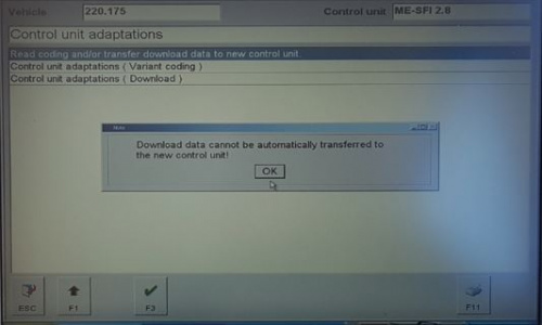
## | # Observe the page Control unit ME-SFI 2.8 with title Control unit adaptations with Note “'''Download data cannot be automatically transferred to the new control unit.'''” | ||
## | #: [[File:20200317 Download data cannot be automatically transferred to the new control unit.JPG|500px|center|thumb|none|Download data cannot be automatically transferred to the new control unit]] | ||
## | # Click '''OK''' to go forward | ||
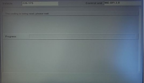
## | # Observe the page Control unit ME-SFI 2.8 with statement “'''The coding is being read, please wait.'''” | ||
## | #: [[File:20200317 The coding is being read, please wait.JPG|500px|center|thumb|none|The coding is being read, please wait.]] | ||
# Click '''OK''' to go forward | |||
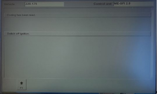
# Observe the page Control unit ME-SFI 2.8 with statement: '''Coding has been read.''' | |||
#: [[File:20200317 Coding has been read.JPG|500px|center|thumb|none|Coding has been read.]] | |||
# Observe statement: '''Switch off ignition.''' | |||
# '''Switch off ignition''' | |||
# Check SDS screen. '''Wait''' until you observe statement: '''Switch on ignition.''' | |||
# '''Switch on ignition and restart engine.''' | |||
# Read the question, “'''Is the coding to be transferred to the new control unit?'''” | |||
#: [[File:20200317 Is the coding to be transferred to the new control unit.JPG|500px|center|thumb|none|Is the coding to be transferred to the new control unit?]] | |||
# Click '''NO F4''' (If required see TIP at beginning of this section to understand why this is done.) | |||
# Observe the page Control unit ME-SFI 2.8 with title '''Control unit adaptations''' | |||
# Highlight '''Control unit adaptations (Variant coding)'''. (This is for manual coding of different features in the vehicle.) | |||
# Click '''F3''' to go forward. | |||
# Observe the page Control unit '''ME-SFI 2.8''' with title '''Control unit adaptations'''. | |||
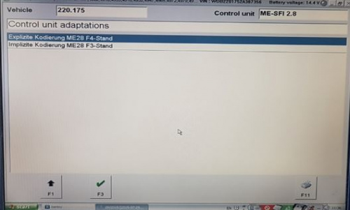
#: [[File:20200317 Control unit adaptations.JPG|500px|center|thumb|none|Control unit ME-SFI 2.8 with title Control unit adaptations]] | |||
# Highlight '''Implizite Kodierung''' [Implicit Coding] | |||
# Select '''F3'''. | |||
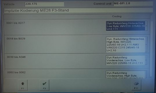
# Observe the page Control unit '''ME-SFI 2.8''' with title '''Implizite Kodierung ME28 F3-Stand'''. | |||
#: [[File:20200317 Implizite Kodierung ME28 F3-Stand.JPG|500px|center|thumb|none|Control unit ME-SFI 2.8 with title Implizite Kodierung ME28 F3-Stand]] | |||
#: TIP: Scroll over all available pages with the heading Control unit ME-SFI 2.8 and title Implizite Kodierung ME28 F3-Stand, and '''photograph all field values as-found'''. Keep as a record in case something goes wrong later. | |||
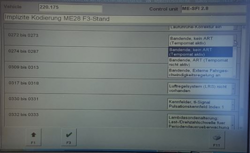
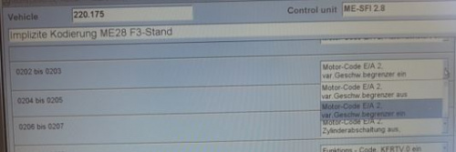
# Scroll up or down the page to '''0272 bis [to] 0273''' and observe field entry '''Bandende, kein ART (Tempomat aktiv)''' [Cruise control active]. | |||
#: [[File:20200317 Bandende, kein ART (Tempomat aktiv).JPG|500px|center|thumb|none|Control unit ME-SFI 2.8 with title Implizite Kodierung ME28 F3-Stand, Bandende, kein ART (Tempomat aktiv) [Cruise control active]]] | |||
# Observe the drop down field options for 0272 bis [to] 0273. | |||
#: TIP: The options translated mean; | |||
#: Bandende, kein ART (Tempomat aktiv) [End of the tape, no ART (cruise control active) or [=Normal Cruise Control and DTR not present]] | |||
#: Bandende, ART (Tempomat nicht Aktiv) [End of the tape, ART (cruise control not active) or [=DTR present or cruise control functionality in traction system and normal Cruise Control inactive]] | |||
#: Bandende externe fahrgeschwindigkeitsregelung [banding external vehicle speed control] | |||
# Highlight '''Bandende, ART (Tempomat nicht Aktiv)''' [End of the tape, ART (cruise control not active)] | |||
# Scroll up or down the page to '''0202 bis [to] 0203''' | |||
# Observe field entry '''Motor-Code E/A 2, var.Geschw.begrenzer ein''' [SPEEDTRONIC present]. | |||
#: [[File:20200317 SPEEDTRONIC present.JPG|500px|center|thumb|none|Control unit ME-SFI 2.8 with title Implizite Kodierung ME28 F3-Stand, 0202 bis [to] 0203 Motor-Code E/A 2, var.Geschw.begrenzer ein [SPEEDTRONIC present]]] | |||
# Observe the drop down field options for '''0202 bis [to] 0203''' | |||
# Highlight '''Motor-Code E/A 2, var.Geschw.begrenzer aus''' [SPEEDTRONIC not present or SPEEDTRONIC functionality in traction system] | |||
# '''F3''' to go forward | |||
# Read the question, “'''Is the coding to be transferred to the control unit?'''” | |||
# Click on '''YES F3''' | |||
# Observe the status, '''The coding is being carried out.''' TIP: If you see “Communication error 8.561.6067” the ME ecu is not unlocked. Go to previous section and unlock ME ecu. | |||
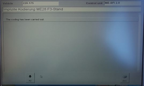
# Observe the statement: '''The coding has been carried out.''' | |||
#: [[File:20200317 The coding has been carried out.JPG|500px|center|thumb|none|Control unit ME-SFI 2.8 with title Implizite Kodierung ME28 F3-Stand, The coding has been carried out.]] | |||
# Click '''F2''' | |||
# Observe the page Control unit ME-SFI 2.8 with title ME-SFI 2.8 F3 – Motor electronics 2.8. | |||
#: TIP: The following confirmation steps may be skipped. | |||
## Highlight Control unit adaptations and click F3 | |||
## Highlight Variant coding and click F3 | |||
## Observe Control unit ME-SFI 2.8 with title Control unit adaptations | |||
## Highlight Variant coding and click F3 | |||
## Observe page Control unit ME-SFI 2.8 with title Variant coding | |||
## Highlight Display of coding data and click F3 | |||
## Observe page Control unit ME-SFI 2.8 with title Display of coding data | |||
## Highlight Coding and click F3 | |||
## Observe page Control unit ME-SFI 2.8 with title Coding | |||
##: TIP: Photograph all as-found field entries for ME-SFI 2.8 with title Coding and keep as a record. | |||
## Scroll down and observe 0202 – 0203 SPEEDTRONIC not present or SPEEDTRONIC functionality in traction system | |||
# Now back out gracefully. | |||
# Observe the page Control unit '''---''' with title '''Control unit groups'''. | |||
#: '''This is the starting page for all DTR adaptations.''' | #: '''This is the starting page for all DTR adaptations.''' | ||
====STEP | ====STEP 10 Reset/Initialize DTR ECM==== | ||
The following steps may be used to | Updated 20200317 | ||
The following steps may be used to reset/initialize DTR electronic control module for a M-B W220 manufactured before 2004-05-31. | |||
In summary: | |||
* Connect battery charger | |||
* Control unit groups | |||
* Drive | |||
* DTR Distronic | |||
* Erase any fault codes or events stored in memory | |||
* Control unit adaptations | |||
* Preconditions | |||
* Is the procedure (initializing DTR ECU) to be carried out now? | |||
* YES F3 | |||
* Control module has been successfully initialized. | |||
* F2 to go forward | |||
* Switch off ignition | |||
* Switch on ignition | |||
* Back out gracefully | |||
In detail: | |||
# Connect battery charger | |||
# Perform the steps for Starting XENTRY above or continue from the last step. | # Perform the steps for Starting XENTRY above or continue from the last step. | ||
# Observe the page Control unit '''---''' with title '''Control unit groups'''. | # Observe the page Control unit '''---''' with title '''Control unit groups'''. | ||
# Highlight ''' | # Highlight '''Drive''', then click '''F3'''. | ||
# Observe the page Control unit '''---''' with title ''' | # Observe the page Control unit '''---''' with title '''Drive'''. | ||
# Highlight ''' | # Highlight '''DTR - Distronic''', then click '''F3'''. | ||
# | # Observe the page '''---''' with title '''DTR – Distronic'''. | ||
# | #: TIP: On some models may need to highlight ARS100/130 (Two-Box) (W220 up to 2004-05-31) and click F3. | ||
# | # '''Clear fault codes'''. | ||
# | # Observe the page DTR with title '''Distronic'''. | ||
# | # Highlight '''Control unit adaptations''', then click '''F3'''. | ||
# | # Observe the page DTR with title Control unit adaptations. | ||
# | # Note the preconditions. | ||
# | # Read the Question; “'''Is the procedure (initializing DTR ECU) to be carried out now?'''”. | ||
# Click '''YES F3''' | |||
# Observe the page Control unit DTR | |||
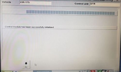
# Observe “'''Control module has been successfully initialized.'''” | |||
#: [[File:20200317 DTR Control module has been successfully initialized.JPG|500px|center|thumb|none|Control unit DTR “Control module has been successfully initialized.”]] | |||
# Click '''F2''' to go ahead | |||
# Observe command “Switch off ignition” | |||
# '''Switch off ignition'''. | |||
# Check SDS screen. | |||
# | # Observe command “Switch on ignition” | ||
# '''Switch on ignition.''' | |||
# | # Now back out gracefully. | ||
# | # Observe the page Control unit --- with title Control unit groups | ||
# | |||
# | |||
# | |||
# | |||
# | |||
# | |||
# | |||
# | |||
#: '''This is the starting page for all DTR adaptations.''' | #: '''This is the starting page for all DTR adaptations.''' | ||
====STEP 11 Check Instrument Cluster==== | |||
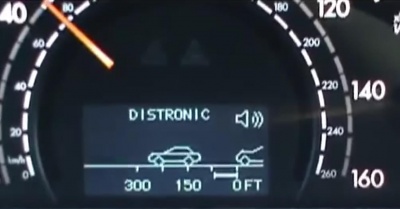
Observe the Instrument Cluster and see the dedicated Distronic Display. In the next photo, the car icon on the left only appears when actually driving about 100m behind a vehicle in front. | |||
[[File:Distronic Retrofit 022.jpg|500px|center|thumb|none|DISTRONIC Display with distance showing in feet (FT)]] | |||
===Activation – W220 after 2004-06-01=== | ===Activation – W220 after 2004-06-01=== | ||
| Line 815: | Line 1,005: | ||
*Have the code number (219) added to the data card, which is the build card ie the factory record of the items installed like Parktronics, TPMS, Voice Command, NAV etc. | *Have the code number (219) added to the data card, which is the build card ie the factory record of the items installed like Parktronics, TPMS, Voice Command, NAV etc. | ||
*Have SCN code added to the Engine Management System. | *Have SCN code added to the Engine Management System. | ||
You can also change engine control unit coding using Vediamo. It is not nessesery to change data card and perform online SCN Coding. | |||
==Calibration – Distronic== | ==Calibration – Distronic== | ||
| Line 833: | Line 1,025: | ||
AR30.30-p-1010Q: Remove/install Distronic sensor (DTR). | AR30.30-p-1010Q: Remove/install Distronic sensor (DTR). | ||
==Notes on Using – Distronic== | |||
DTR will '''NOT''' engage: | |||
* For up to two minutes after engine start-up (This is the initialization or self test phase.) | |||
* Vehicle speed < 25 Km/h or mph | |||
* With Parking Brake activated | |||
* With ESP manually switched OFF | |||
* If gear selector is NOT in position 'D' | |||
DTR may be controlled in the same manner as the Cruise Control or Speed Limiter. | |||
DTR will switch off automatically for the same reasons as Cruise Control. | |||
The Distance potentiometer on the Centre Console regulates the DTR "following interval", or distance to the lead vehicle, from 1 to 2 secs. | |||
DTR screen can be displayed in the instrument cluster while driving without engaging cruise control (the word DISTRONIC doesn’t appear). | |||
DTR audible warnings are active without cruise control engagement, unless switched off by driver using the DTR switch on the Centre Console. | |||
DTR will not apply the brakes to slow the vehicle while driver is using the accelerator to exceed the DTR speed setting. | |||
If DTR display shows “ ---“ instead of the current vehicle speed may be due to dirt, snow or ice build up on the radar sensor or road mist, heavy rain or fog which can reduce radar signals enough to cause difficulty in detecting vehicles ahead. | |||
Latest revision as of 15:43, 20 July 2023
Description - Distronic and Distronic Plus
The Distronic system in Mercedes-Benz is an important feature to maintaining the selected vehicle speed (cruise control function) and also regulating the distance to a vehicle ahead of the car.
The Distronic detects the traffic situation ahead of the vehicle by means of the radar sensor located behind the radiator grille. If the Distronic approaches another vehicle travelling at a slower speed, the speed of the car is reduced. The Distronic control unit calculates the distance required and can activate the following over the CANbus:
- Increase/reduction in the specified engine speed (Engine management control ME-SFI(ME) control unit),
- Braking (Electronic Stability Program (ESP) control unit),
- Shifting gears (Electronic transmission control (ETC) control unit).
The Distronic can be used from a speed of approx. 30 Km/h to 180 Km/h or 20 mph to 110 mph. If no vehicle is driving ahead, the Distronic behaves in the same way as a normal cruise control.
The Distronic is a convenience system and not a safety system. The driver must himself brake when corresponding traffic situations arise.
If a vehicle suddenly appears ahead (e.g. as a result of changing lanes), the Distronic attempts to take control. The braking action is, however, limited to approx. 2 m/s (which equals approximately 20% of the maximum braking power) for safety reasons. If more braking power is required, the driver is warned by means of an audible signal.
There is also a further audible signal (off signal) which sounds if the vehicle speed drops below approx. 30 Km/h.
If the speed set with the cruise control lever is exceeded by depressing the accelerator pedal, the distance measurement of the Distronic continues to remain active even above 180 Km/h (110 mph). The Distronic again controls the vehicle to the speed last set after the accelerator pedal is released.
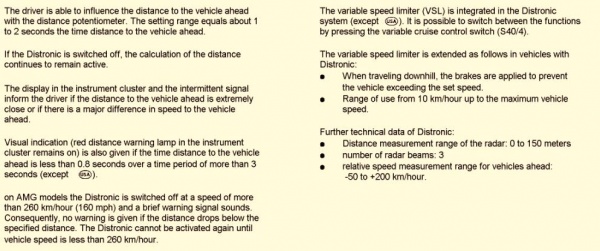
The driver is able to influence the distance travelled behind the vehicle ahead with the distance potentiometer mounted in the centre console adjacent to the gear lever. The setting is actually a time setting of about 1 to 2 seconds.
If the Distronic is switched off, the calculation of the distance continues to remain active.
The display in the instrument cluster and the audible warning signal inform the driver if the distance to the vehicle ahead is extremely close or if there is a major difference in speed to the vehicle ahead. Visual indication (red distance warning lamp in the instrument cluster remains on) is also given if the time distance to the vehicle ahead is less than 0.8 seconds over a time period of more than 3 seconds.
The distance measurement range of the Distronic radar unit is 0 to 150 m.
Distronic
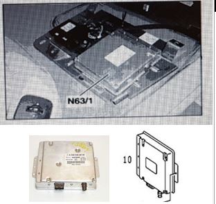
In W220 models UP TO 2004-05-31 with Data Card CODE 219, the Proximity Controlled Cruise Control Distance Radar (Distronic) system consists of a Radar Sensor (B29) (Item #30) and a separate Electronic Control Unit (ECU) (N63/1) (Item #10).
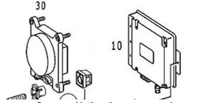
- The Radar Sensor (B29) (Item #30) is located behind the front radiator grill.
- The Distronic Electronic Control Unit (ECU) (N63/1) (Item #10) is located in the front passenger footwell (both LHD and RHD vehicles, ie always the passenger footwell) and is connected to several control units via the CAN-C bus.
When following vehicles that are slowly decelerating the Distronic disengages at 30Km/h or 20 mph. The Distronic will alarm with an audio and visual alert when the closure speed is not to its liking - the system can be turned on or off for that function.
The original video ‘Mercedes S-Class Distronic Cruise Control' in operation in a W220 is here;
Distronic Plus
In W220 models FROM 2014-06-01 the Proximity Controlled Cruise Control Distance Radar system was renamed as Distronic Plus and was simplified with all the electronics now in an integrated radar sensor and control unit (A89) mounted behind the front grill. Note that for these later A89 Distronic Plus systems, there are different connector versions for models 209/215/220 and 211/219/230.
In these later models the Distronic Plus is more of an anti-collision system. It works great even in stop and go traffic situations and will even bring the car to a complete stop when needed. After a complete stop of more than three seconds, you just need to pull the cruise control stalk towards you and the car will accelerate. No need to touch the pedals!
Another great feature of Distronic Plus is that when you change lanes it accelerates as soon as you turn the turn signal on! For example, if your set speed is 100, but you are going at 80 because there is a car in front of you, as soon as you turn the left turn signal on, the car will start to accelerate if there is no car in the left lane. Very useful when you need to squeeze in between two cars!
Think of Distronic Plus as a robotic driving system that takes over from cruise control when the car detects another car in the 200m distance ahead, which is way beyond the recognition distance for the braking system sensors. While there is a car in front Distronic Plus takes over from cruise control and tracks the car in front, maintaining a constant time gap as traffic speeds and slows. This mostly controls the throttle but will also brake in necessary. When the car in front gets too far in front the system then hands over to cruise control.
When following vehicles that are slowly decelerating the Distronic disengages at 30Km/h or 20 mph. The Distronic Plus will alarm with an audio and visual alert when the closure speed is not to its liking - the system can be turned on or off for that function.
A video of a Distronic Plus in operation in a 2013 M-B B250 is here;
Issues - Distronic
Retrofitting -Distronic
Is it possible to retrofit Distronic Cruise Control Radar functionality to a W220?
Thanks to BenzWorld member,David Prokity’s Project on his 2006 S430 recorded on video on YouTube, it is, and he states “This is absolutely the best option I have ever retrofitted”. David Prokity did the research and the physical install of the hardware and wiring. The reprogramming of the vehicle computer was outsourced. He was able to retrofit a W220 MY00 and a C215 MY04. He states that beside the horrible cost if you have to buy new parts, it's an easy and straight forward installation. BUT "Make sure that you have all the correct part numbers before you are starting".
The part which is a little more complicated is the coding. W220's up to 2004-05-31 have no SCN coding and all coding can be done with an offline DAS System. Later on more and more SCN coding was introduced to all M-B models and nowadays you need to have your your datacard modified by M-B Stuttgart first, then pull the required SCN codes with an Online DAS.
Coaxial Cable Failure - Distronic
The coaxial cable that feeds analogue signals from the Radar Sensor to the Distronic Control Unit can deteriorate through age or abuse. Be warned that during replacement of the coaxial cable, make sure not to bend it severely by maintaining a minimum radius of 25mm or more.
Distronic Components - W220 up to 2004-05-31
For W220 up to 2004-05-31 with Data Card CODE 219 as per information found in WIS.
Distronic Function Description Contents

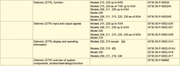
Distronic Function

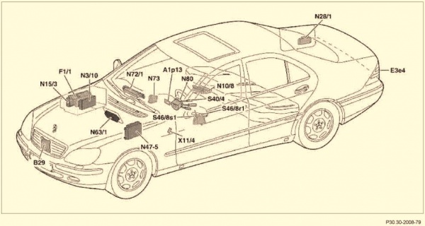

- Note Diagram is WRONG. N73 is the Electronic Ignition Switch (EIS) control unit and not the DI control unit.



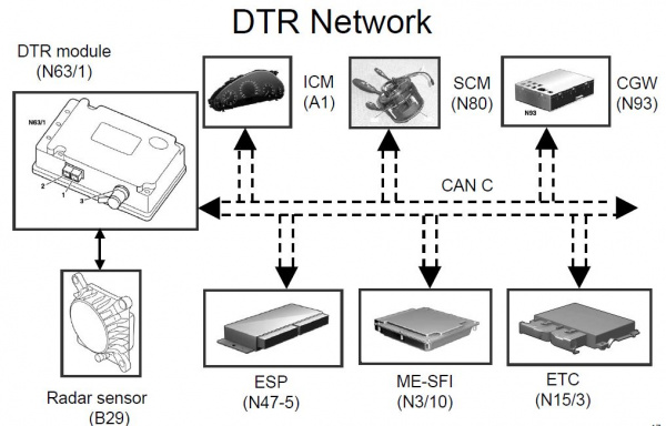
Distronic Network and Input and Output Signals
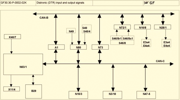

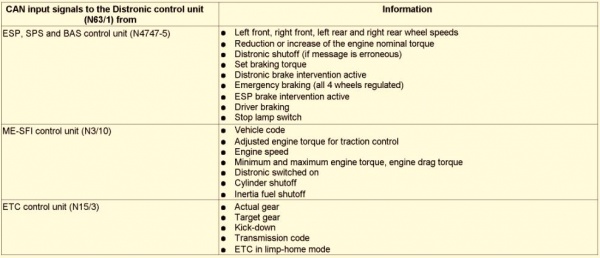

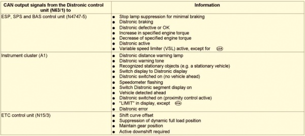

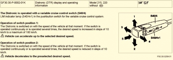
Distronic Display and Operating Information



Distronic Radar Sensor - Location Task Design Function
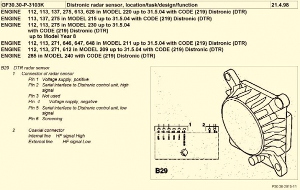


Distronic Radar Sensor - Location

Distronic Control Unit - Location Task Design Function

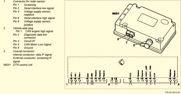
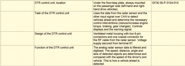
Distronic Control Unit - Location


Switch Block - Location Task Design Function
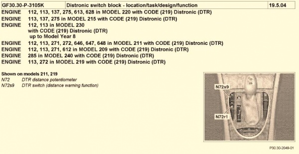

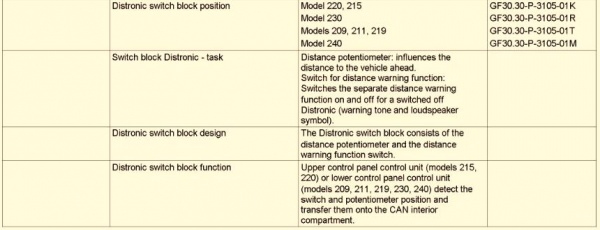

Distronic Component Diagram - W220 up to 2004-05-31
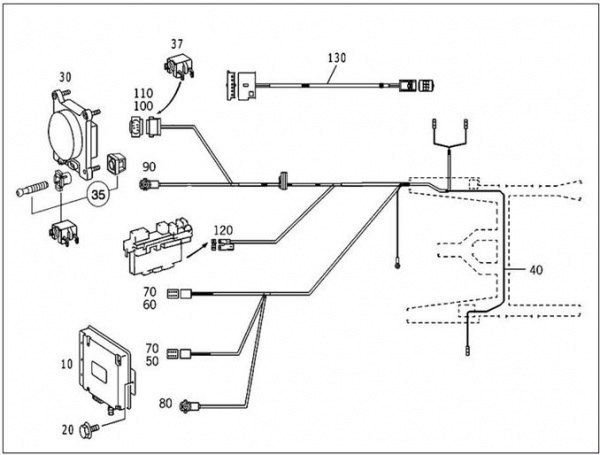
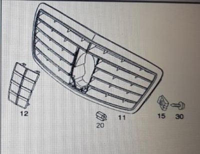
- Item #10 Control Unit (N63/1)
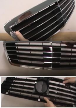
- Item #11 Panelling for Adaptive Cruise Control or Distronic grill (with the plastic window Item #12 for the protection of the radar sensor)
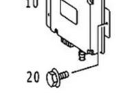
- Item 20 Mounting Bolts Control Unit
- Item #30 Radar Sensor Unit (B29)
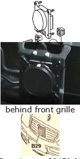
- Item #35 Mounting Kit Radar Sensor Unit
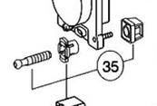
- Item #40 Wiring Harness
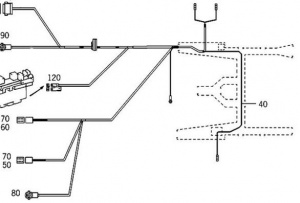
- Item #115 Switch block (S46/8).
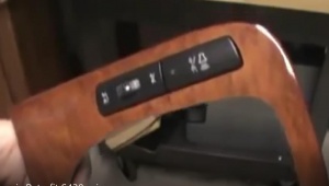
- Item #130 Electrical Cable Upper Control Panel (N72/1) to Switch block (S46/8).
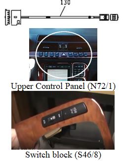
Part Numbers- Distronic
How to Find Distronic Part Numbers
startekinfo
Note startekinfo is not able to accept non-US credit cards as some of the technical information is U.S. Government-regulated.
Get help from someone on BenzWorld to access startekinfo [1]
Then key in your VIN and look for the Distronic parts, you will see a list of interchangeable part numbers.
SDS EPC
Using a Star Diagnostic System (SDS) open the Electronic Parts Catalog (EPC).
The trick is to NOT enter your VIN, but do the following;
- Select MD mode.
- In Assortment class, select 1. Car.
- In Model designation, select relevant model eg 220176 S 500.
- In Market, select relevant field eg Europe.
- In Group, select 54 ELECTRICAL EQUIPMENT AND INSTRUMENTS.
- In Subgroup select, 755 PROXIMITY-CONTROLLED CRUISE CONTROL.
- Observe the generic parts diagram identifying Item nos. and Part numbers.
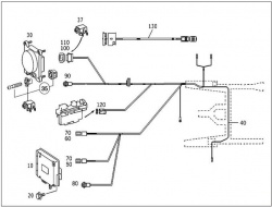
If you do use your VIN then open Options, Filter, and Untick or Disable the Datacard SA filter.
Then you have the option to see all the required and valid parts for the VIN designated model, even without Distronic fitted.
Look at EPC, 54 Electrical Equipment and Instruments, 755 Proximity Controlled Cruise Control.
mbpartsworld
Access mbpartsworld website [www.mbpartsworld.com] and search for relevant model.
Distronic Part Numbers - W220 up to 2004-05-31
There is a plethora of part numbers as Distronic is used on many different models of M-B cars.
The following are given as a guide for W220 up to 2004-05-31 but must be double checked before purchasing for your specific vehicle.
- Item #10 Control Unit (N63/1) 031 545 64 32 replaced by 032 545 90 32 replaced by 032 545 56 32 replaced by 032 545 63 32.
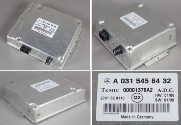
- Item #11 Distronic grill with the plastic window for the protection of the radar sensor 220 880 06 83

- Item #20 Mounting Bolts Control Unit 140 990 06 36 or 3 off M5x14 bolts.
- Item #30 Radar Sensor Unit (B29) 000 540 88 17
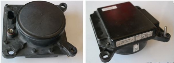
- Item #35 Mounting Kit Radar Sensor Unit 001 540 63 17
- Item #40 Major Wiring Harness 220 540 85 07 (or 230 540 94 07 To be confirmed).
- Item #130 Electrical Cable Upper Control Panel (N72/1) to Switch block (S46/8) 220 540 37 32

- Item #115 Switch block (S46/8) with distance potentiometer (S46/8r1) and distance warning function switch (S46/8s1) 220 821 87 58 7C4 (or 230 821 28 51 7167 or 120 820 10 10 7167 To Be Confirmed)
Distronic Part Numbers - W220 after 2004-06-01
Parts for Distronic after 2004-06-01 are a bit different. Main difference is radar unit witch is no longer two-box, instead is only radar and module in one. Wiring harness is also different, it just contains fuse holder, ground connection and CAN-H and CAN-L connection. Grill and switches inside car are the same as before.
Parts that has been changed:
Wiring harness - A2205405930
Radar and module unit - A2205454232
Availability - Distronic Parts
MBenzNL
Website [2]
Facebook [3]
Email [mbenznl@gmail.com]
Note as of June 2018, Steve from MBenzNL advises that "the main wiring harness for the older Distronic systems is no longer available for the W211 E-class and the W220 S-class. M-B no longer has them in stock and does not get them manufactured anymore. And be warned, getting yourself a used wiring harness is not ideal either because of the COAXIAL cable that runs from the Distronic Control Unit to the Distronic Radar Sensor, as that cable cannot stand much abuse before it does not work properly."
An alternative is available but requires modification. The harness from a R230 SL 500 is very similar to an early W220 harness. The coax cable is just long enough but if fitting to a RHD vehicle, the earth wire (brown) and the diagnostic wire (pink) require extending by about 1.5 metres. The R230 230.471 SL 500 part number is 230 540 94 07. TIP: when installing the cable in a RHD car, make sure to keep the cable as tight as possible, ie do not allow too much slack as the full length of the coax cable will be needed to reach the Distronic Control Module (DTR).
eBay
As always search for OEM part number in first instance.
Retrofit Method – Distronic
Be aware that the method varies for W220 up to 2004-05-31 and W220 after 2004-06-01.
W220 up to 2004-05-31 - Distronic Retrofit
2000 up to about 2004 W220’s had no SCN coding and all coding can be done with an offline DAS System.
The WIS document GF30.30-P-0002-02K Distronic (DTR) input and output signals shows Distronic control module N63/1 connected directly to;
- B29 Distronic radar sensor (DTR)
- K40/7 Right front fuse and relay module (terminal 87 voltage supply)
- X11/4 Data link connector
It is connected via the CAN-C engine compartment bus to the following;
- A1 Instrument cluster (ICM)
- N80 Steering column module (SCM-MRM)
- N73 Electronic ignition switch (EZS/ZGW) control unit
- N15/3 Electronic transmission control (ETC) control unit
- N3/10 Engine management control ME-SFI(ME) control unit
- N47-5 Electronic Stability Program (ESP), Speed Sensitive Power Steering (SPS), Brake Assist (BAS) control units
It is connected to the CAN-B interior bus via gateway N73 (EIS) which communicates to;
- N72/1 Upper control panel (UCP) control unit and then the S46/8 Switch Block in centre console.
- N10/8 Rear SAM control unit (REAR SAM)
- N28/1 Trailer recognition control unit (special equipment)
Retrofit Method - W220 up to 2004-05-31
Even though David Prokity's video shows a Distronic being retrofitted to a post 2004 vehicle it is a very useful tutorial on how to fit the components to all models, especially installing the wiring harnesses and the connection to the right fuse box.
He acknowledges the valuable assistance from:
- Steve Krabbenborg of MBenzNL (www.MBenzNL.nl) for his help in sending the correct parts and telling him how to calibrate the Distronic Radar Unit.
- Wanda Klein Gunnewiek of MBenzNL for answering his endless installation questions.
- Sunil Patel of Motorwerks of Houston for actually enabling the Distronic System.
- Without those three individuals his project would have never happened.
Also see the method used by mercupgrade.com to retrofit a Distronic to a 2004 SL55 using a "two box" Distronic here [4]
Mercupgrade states "This reference describes how to retrofit Distronic to a MY2004 or older SL55. The pictures are from a Right Hand Drive car, but there is LHD information in this document."
The following summary is a combination of the Mercupgrade article modified to suit a 2003 (upgrade) W220.
- Disconnect battery.
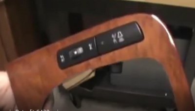
- Disassemble the centre console in order to install the Distronic Switch Block (S46/8) with distance potentiometer (S46/8r1) and distance warning function switch (S46/8s1), mounted in the new wood grain panel. TIP: To remove the gear knob, turn the ferrule under the knob to release the catch and then pull the knob directly upward.
- Remove the COMAND from the dash. TIP: It is not necessary to remove the COMAND which can stay connected.
- Run the new "minor" Electrical Loom from the Switch Block (S46/8) behind the COMAND unit to the Upper Control Panel (N72/1). Plug the cable in to the empty slot in the UCP at the far left end.
- Install the Distronic Radar Sensor Unit (B29).
- Route the wiring loom starting from the Radar Sensor Unit (B29), to the Right Fusebox in the engine bay. TIP: Keep the loom as tight as possible so that it will reach the Distronic Control Module (N63/1). TIP: Remove the engine bottom cover and the front protection shield behind the front bumper to gain access for the wiring. TIP: Remove the FR inner wheel guards to route the loom behind and around the AIRmatic pump.
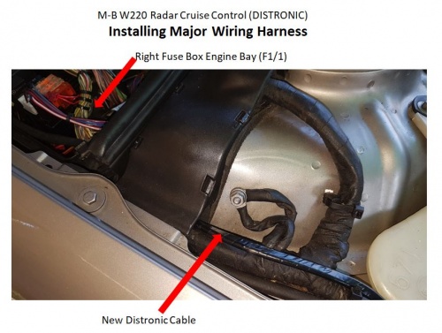
- There is already a hole in a grommet to allow the new Distronic loom to enter the Front Right Engine Bay Fusebox (F1/1).
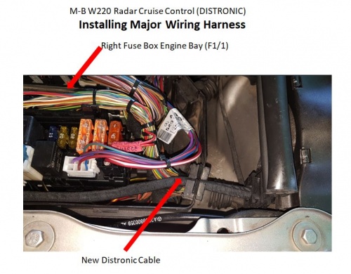
- Remove the Front Right Engine Bay Fusebox (F1/1). TIP: The Fusebox can be placed to one side to allow good access for routing the Distronic cable throughh the firewall into the FR foot well.
- Remove the FR floor carpet. TIP: On a RHD drive car remove the accelerator pedal first.
- Using a plastic rod or stiff wire with the end of the Distronic cable temporarily taped to it, push through the opening into the FR foot well.
- Pull the wiring loom through to the inside of the vehicle.
- Install Distronic fuse carrier into the empty position f36 in the the Front Right Engine Bay Fusebox (F1/1). TIP: f36 is the third fuse counting from the rear.
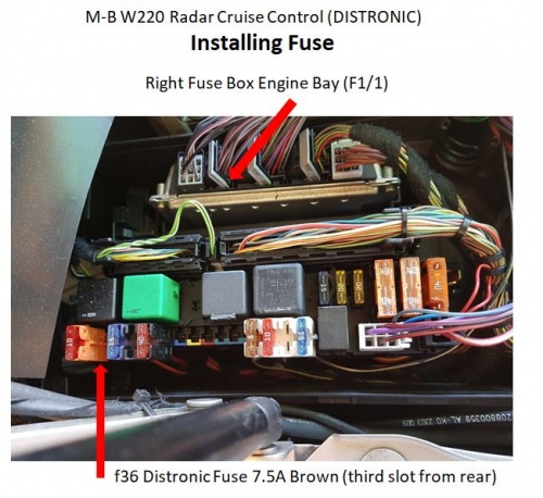
- On LHD vehicles, connect the earth lead to the earth point in the FR foot-well. On RHD vehicles either connect the earth lead to the earth point in the FR foot-well or extend the earth wire (brown) by about 1.5m so that it will reach the FL foot-well earth point.
- On LHD vehicles install the Distronic Control Module (N63/1) on the FR (passenger) aluminium floor plate and connect the loom. TIP: For RHD vehicles, skip this step.
- Remove the FL floor carpet.
- Using a plastic rod or stiff wire with the end of the Distronic cable temporarily taped to it, push through behind the COMAND to the FL foot-well
- On RHD vehicles install the Distronic Control Module (N63/1) on the FL (passenger) aluminium floor plate and connect the loom. TIP: You may need to re position the control module on the aluminium floor plate rather than use the OEM mounting holes, in order to allow the Distronic coax cable to reach the appropriate connector.
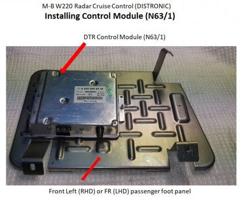
- Route the remaining Distronic loom to the FL cable ducting in the floor.
- Connect the Distronic loom twisted pair (green and green/white) to any similar "engine" CAN bus twisted pair in the cable duct. TIP: Ensure the green CAN-CL wires are connected together and the green/white CAN-CH wires are twisted together.
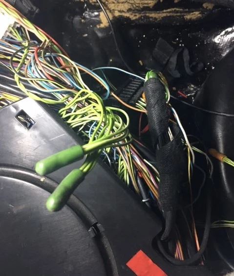
- Connect the Distronic loom diagnostic wire (pink) to the blue/white wire on connector X35/66 in FL foot-well cable ducting. TIP: X35/66 is the large black connector. TIP: The diagnostic wire X35/66 pin 8 (blue/white) goes to the OBDII port X11/4 pin 15 which is used by Star DAS to communicate with the DTR.
- Take vehicle to a Mercedes dealer for coding and most importantly for Distronic sensor alignment. TIP: If the car is a pre 2004-05-31 model the coding can be done using a Star DAS with Developer Mode.
TIP: Apart from the alignment of the Distronic sensor the vehicle will have to be coded to activate/enable the Distronic:
- Drive > ME (Engine Management): Either have Option 219 added to the datacard and SCN code the Engine Management system (best), or using Star Diagnosis with 'Factory Mode or Developer key' and enable Distronic/DTR. (NB. if you don't have option 219 added to the datacard and the engine management system is SCN coded in the future, then not only will Distronic not work, but there will be an ESP error and various other issues).
- Body > System Diagnosis: Enable DTR/Distronic. (This is for diagnosis purposes).
- Body > CGW (Central Gateway): Enable DTR/Distronic. (This tells the lower control panel and ESP the car has Distronic, so once this is done the button for Distronic will light up).
- Info & Communication Systems > ICM (Instrument Cluster): Enable DTR/Distronic. (This enables the menu on the cluster).
W220 after 2004-06-01 - Distronic Retrofit
After 2004-06-01 SCN Coding has been introduced, which close the way to use only DAS. To change coding in your car you have to add code 219 to your data card, then perform online SCN coding by dealership or some independent workshops. Rest of modules such as Instrument Cluster, CGW, EZS have to be coded and it can be activated offline by DAS. If you have access to Star Diagnosis you can change variant coding in ECU by Vediamo. (I have tried Vediamo by myself and I changed it successfully).
Retrofit Method - W220 after 2004-06-01
See the excellent video by David Prokity;
Activation/Adaptation/Coding – Distronic (DTR)
Vehicle control unit Activation/Adaptation/Coding/Programming is necessary after:
- Replacement of DTR control module (N63/1)
- Replacement of steering angle sensor (N49)
- Removal of steering wheel
- Replacement or adjustment of radar sensor (B29)
- Exchange or repair of chassis components including setting wheel toe.
The N63/1 Distronic (DTR) ecu connects directly to these components;
- B29 Distronic Radar Sensor
- K40/7 Right front fuse and relay module (terminal 87 voltage supply)
- X11/4 Data link connector
The N63/1 Distronic (DTR) ecu connects via the CAN-C engine bus to these components;
- N73 Control gateway gateway (CGW)
- A1 Instrument control module (ICM)
- N80 Steering column module (SCM-MRM)
- N73 Electronic ignition switch (EZS/ZGW)
- N15/3 Electronic transmission control (ETC)
- N3/10 Engine management electronics (ME-SFI)
- N47-5 Electronic Stability Program (ESP), Speed Sensitive Power Steering(SPS), Brake Assist (BAS)
The N63/1 Distronic (DTR) ecu connects via the CAN-B interior bus via Control gateway (CGW) ecu which communicates to;
- N72/1 Upper control panel (UCP) and then the S46/8 Distronic Switch Block in centre console.
- N10/8 Rear SAM control unit (REAR SAM)
- N28/1 Trailer recognition control unit (special equipment)
The N63/1 Distronic (DTR) ecu connects indirectly to these components;
- N49 Steering Angle Sensor
- S40/4 Cruise Control Switch
- S46/8 Console Switches
- A7/7y1 BAS solenoid valve
Distronic requires control unit adaptation in these ecu's and preferably in this order;
- Central gate way (CGW)
- Electronic ignition switch (EZS)
- Instrument cluster with maintenance display (ICM)
- Upper control panel (UCP)
- Motor electronics (ME-SFI)
- Distronic (DTR)
TIP: Be aware of the difference between Control unit adaptations and Control unit adaptations done in Development Mode. The former allows access to the main codes for a vehicle and should be used in most situations. The latter allows access to these main codes plus a lot of normally hidden codes and should only be used by experienced persons.
BE WARNED: Activation requires specialized expertise. Distronic activation with Star Diagnosis System (SDS) off-line is not possible for vehicles manufactured after 2004-06-01. ESP SPS BAS errors will result. These cars require coding using the SCN system via an on-line SDS. On these later model cars if you don't have option 219 added to the datacard and the engine management system upgraded to the latest version, then the Distronic will not work and an ESP error will alternate with SRS warnings on the instrument panel. Even if the vehicle is manufactured before 2004-06-01 similar ESP SPS BAS error messages may appear on the Instrument Cluster. The ME ecu should be updated to the latest version before undertaking this project.
TIP: The following steps and associated photographs may differ for different years and models of M-B cars.
TIP: Each Step has a summary and a detailed description. The summary is useful as a hard copy and can be used to guide you through the steps. It is recommended that you print out the summary for each step before starting.
Activation – W220 before 2004-05-31
W220 manufactured before 2004-05-31 do not require SCN coding and hence Distronic (DTR) Adaptation may be performed with an off-line SDS using Developer Mode.
The method for adapting the Distronic (DTR) is very similar to that used for changing the top speed limit (factory coded setting Vmax) of an AMG. BenzWorld member Bayhas Kana has posted a video [5] on this topic and it is a useful guide for retrofitting the DTR as far as the coding is concerned. Also see; [6].
Note: The author prefers to use a list of steps rather than a video as a tutorial because it can be printed and each step ticked off as they are completed.
Update 20200314: Success at last! The author, BenzWorld member 'ricebubbles' can now report the successful installation and coding of a Distronic in a 2003 Update W220 S500L. The project took 18 months and a lot of agony reverse engineering the various Variant codes, mostly in German, using an off-line Star Diagnosis System. The trick was to investigate every possible option for every electronic control unit, looking for anything possibly related to Cruise Control (most common cruise control fitted), Speedtronic (speed limiter) and Distronic (radar cruise control). The secret to the author's success was to find the Variant code in the CGW ecu for "CAN-C: Abstandsassistent" [=CAN-C: Distance Assistant] which was coded "nicht vorhanden" [=not available] and once this was changed to "vorhanden" [=available], along with the other more obvious changes shown below, the system worked perfectly.
The author used to think that the Speed Limiter was the best device in the W220, but now having tried Distronic, rates Distronic equal best with the Speed Limiter. It is the best modification done to his W220.
The following steps have been edited to reflect the successful procedure. Be aware that other cars may require different or additional steps.
The steps required for activating Distronic or Distance Tracking Radar (DTR) using Star Diagnosis System (SDS) with 'Factory Mode or Developer key' are as follows.
- Start XENTRY
- Configure COM Port from 19,200 to 9,600 bps.
- Add Distronic in control unit CGW (Central gate way)
- Confirm Distronic in control unit CGW (Central gate way)
- Enable Distronic in control unit EZS (Electronic ignition switch)
- Enable Distronic in control unit ICM (Instrument cluster with maintenance display)
- Distronic and control unit UCP (Upper control panel)
- Unlock control unit ME-SFI 2.8 (Motor electronics) for Programming
- Enable ART in ME (Using Implizite Kodierung [Implicit Coding])
- Reset/Initialize control unit DTR (Distronic)
- Clear all fault codes
STEP 00 MUST READ Preliminary
SDS XENTRY is a real pain to use when changing the Motor Electronic (ME) ecu, especially the ecu unlock step, which nearly always took many attempts (using the same technique) before it would unlock.
It also helps to understand that there are two main modes of operation of XENTRY. The simplest, accessed via each ecu and Control unit adaptations return the Variant codings and the set option in English. This is how to open the ME ecu in this mode;
- ME Variant coding via Control unit groups > Drive > ME-SFI 2.8 > Control unit adaptations > Variant Coding > Display of coding data > Coding.
The second mode, which is extremely powerful and if not used carefully, slowly and with considerable thought before each step, can end up "bricking" the car, ie rendering it useless, so be warned. It is called Developer mode and returns the Variant codings and the set and available options in German, so having a translation available before starting is essential. It is possible to create a reasonable translation by reading all the possible codes in the normal/simple mode (in English) and repeating in Developer Mode (in German) and comparing the two, line by line. This is how to open the ME ecu in this Developer Mode;
- Control unit groups > Drive > ME-SFI 2.8 > Development data > Control unit adaptations > Read coding and/or transfer download data to a new control unit > Control unit adaptations (Variant Coding) > Implizite Kodierung
A warning about Explizite Kodierung. As far as the author can ascertain, Explizite Kodierung seems to be a quick way for the factory to set multiple variant codes for a particular vehicle, with just a few mouse clicks in SDS. The same codes may be set, one by one, using Implizite Kodeirung, in a more controlled fashion. It took the author several days to recover after using Explizite Kodierung to change the ME ecu to what he thought was the correct vehicle. As well as making a couple of required changes, the SDS also changed a heap of other parameters and upset the vehicle completely. For example, the tyre settings changed to some weird specifications, which affected the Speedometer, Cruise Control and Speed Limiter (no Distronic at this stage) which were all different and out compared to a GPS speed indication by a factor of 1.9. TIP: Before you start on this or a similar project, make sure you have created a full backup record of every setting for every ecu, just in case something goes wrong. The translation printouts, if they are complete, will help in this regard, but you cannot beat having a photograph of every setting. Fortunately the author found some old photographs from two years before the Explizite Kodiering mistake, otherwise he would not have been able to recover without a lot of trial and error.
The author found an Internet suggestion that the engine needs to be running and idling, for ME control unit programming to be properly stored and committed, didn't apply in his case. The vehicle MUST be connected to a battery charger though, and the car voltage (as seen on SDS) should not go below 12.6V.
TIP: Enthusiasts who have attempted changing coding using SDS seem to have discovered a possible quirk/bug in the SDS software;
SDS appears to read the existing ecu settings, then when the screen appears, the fields are blank (actually "- - -"), and SDS states that one or more setting is invalid. This quirk is mostly overcome by first using "Read coding and/or transfer data to a new control unit" just to read the data, (but do not transfer the read codes to a "new control unit" by pressing the "NO F4" button at the appropriate time. All going well, SDS will actually show the current values for the ecu. The author found in the EIS (EZS) ecu that he coudn't get rid of the blanks and went ahead with the required changes any way, leaving most of the fields blank, and it didn't seem to matter if the fields as read/observed were left blank. The required changes were successfully made.
STEP 01 Starting XENTRY
Connect SDS (must have Developer Mode enabled) to vehicle
- Open XENTRY Diagnostics.
- Observe XENTRY, Brand > Product Group.
- Click on vehicle eg S (220).
- Observe XENTRY, Brand > Product Group > Vehicle.
- Highlight the required model eg 220.175 – S500 and click Continue.
- Observe XENTRY, Brand > Product Group > Vehicle > Transmission/engine.
- Highlight the relevant Engine eg 113.960.
- Highlight the relevant Transmission eg 722.901 and click Continue.
- Observe XENTRY, Brand > Product Group > Vehicle > Transmission/engine > Overview – Identification is complete.
- Click on the stethoscope icon on left to start Xentry Diagnostics application.
- Observe NOTES re damage to electronic components.
- Click F2 to accept NOTES and go forward.
- Observe NOTES re Sicherheitshinweise [Safety instructions]
- Click F2 to accept NOTES and go forward.
- Observe several windows with “Vehicle data are being read...”.
- Wait while “Data are being determined, please wait…”
- Observe the page Control unit --- with title Main groups.
- Highlight Control units then click F3.
- Observe the page Control unit --- with title Control unit groups.
This is the starting page for all DTR adaptations.
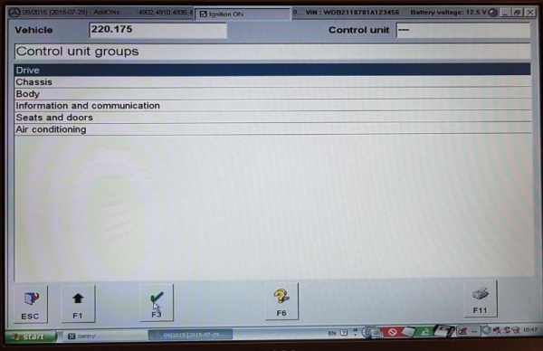
STEP 02 Add DTR to CGW
Updated 20200314
The following steps may be used to add Distronic (DTR) availability to the Central Gateway (CGW) electronic control module for a M-B W220 manufactured before 2004-05-31. This tells the UCP and Electronic Stability Programme (ESP) that the car has Distronic, so once this is done the button for Distronic will light up.
In summary:
- Control unit groups
- Body
- CGW – Central gateway
- Clear any faults or events stored in memory
- Development data
- Main menu of control module ZGW
- Control unit adaptations
- Read coding and/or transfer download data to a new control unit
- Coding has been read
- Switch off ignition
- Switch on ignition
- Replace the old control unit with the new control unit
- NO F4
- Control unit adaptations (Variant coding)
- Globale Variantencodierung [Global variant coding]
- Abstandsregeltempomat [Adaptive cruise control]
- Change nicht vorhanden [not available] to vorhanden [available]
- CAN-C: Abstandsassistent [CAN-C: Distance Assistant]
- Change nicht vorhanden [not available] to vorhanden [available]
- Abstandsregeltempomat [Adaptive cruise control]
- Is the coding to be transferred to the control unit?
- YES F3
- The coding has been carried out.
- Back out gracefully
In detail:
- Connect battery charger
- Perform the steps for Starting XENTRY above or continue from the last step.
- Observe the page Control unit --- with title Control unit groups.
- Highlight Body, then click F3.
- Observe the page Control unit --- with title Body.
- Highlight CGW – Central Gateway , then click F3.
- Observe the page Control unit CGW with title CGW.
- Note: Before performing any adaptation coding any existing fault codes and event memory records should be erased.
- A. Highlight Fault codes, then click F3.
- B. Observe the page Control unit CGW with title Fault codes.
- C. If there are Fault codes present erase them by clicking F9.
- D. Note the question. Do you really wish to erase fault memory? If you delete fault codes, stored events will also be deleted.
- E. Click YES.
- F. If there are no Fault codes go back by clicking F1.
- G. Observe the page Control unit CGW with title Fault codes.
- H. Now check there are no remaining events stored in the car’s memory.
- I. Highlight Event memory and click F3.
- J. Observe the page Control unit CGW with title Event memory.
- K. If there are Event memory codes present erase them by clicking F9
- L. Note the question. Do you really wish to erase event memory? If you delete events, fault codes will also be deleted.
- M. Click YES.
- N. If there are no Event memory codes go back by clicking on F1.
- Observe the page Control unit CGW with title CGW.
- Highlight Development data and click F3.
- Observe the page Control unit CGW with title Main menu of control module ZGW.
- Important Note: The engine needs to be running and idling, for ME ecu programming modification to be properly saved and permanently stored.
- Highlight Control unit adaptations and click F3.
- Observe the page Control unit CGW with title Control unit adaptations.
- Highlight Read coding and/or transfer download data to a new control unit
- Click F3.
- Observe the page Control unit CGW with title Control unit adaptations.
- Observe the Warning; When replacing different control module versions (e.g. Q1 for Q2), wrong coding can occur. For this reason the code settings must be check (sic) under ‘Control unit adaptations (Variant coding)’.
- Click OK to go forward.
- Observe the page Control unit CGW with statement “The coding is being read, please wait.”
- Observe the page Control unit EZS with statement: “Coding has been read.”
- Observe statement: “Switch off ignition.”
- Switch off ignition and check SDS screen. Wait until observe statement: “Switch on ignition.”
- Observe the page Control unit CGW with statement Replace the old control unit with the new control unit.
- Observe statement: “Switch on ignition.”
- Switch on ignition
- Read the question, “Is the coding to be transferred to the new control unit?”
- Click on NO F4 (See TIP at beginning of this step to understand why this is done.)
- Observe the page Control unit CGW with title Control unit adaptations
- Highlight Control unit adaptations (Variant coding).
- Note: This is the command for manual coding of different features in the vehicle.
- Click F3.
- Observe the page Control unit CGW with title Control unit adaptations.
- Highlight Globale Variantencodierung [Global variant coding], then click F3.
- Observe “The coding is being read.”
- Observe page Control unit CGW with title Globale Variantencodierung [Global variant coding]
- Scroll up or down the page to see Abstandsregeltempomat [Adaptive cruise control]
- Observe option nicht vorhanden [not available]
- Use drop down menu to select vorhanden [available]
- Scroll up or down the page to see CAN-C: Abstandsassistent [CAN-C: Distance Assistant]
- Observe option nicht vorhanden [not available]
- Use drop down menu to select vorhanden [available]
- Scroll up or down the page to see Abstandsregeltempomat [Adaptive cruise control]
- Select F3 to go forward
- Observe statement “Is the coding to be transferred to the control unit?”
- Select YES F3
- Observe “The coding is being carried out.”
- Observe “The coding has been carried out.”
- Now back out gracefully.
- Observe the page Control unit --- with title Control unit groups.
- This is the starting page for all DTR adaptations.
STEP 03 Confirm Distronic in CGW
Updated 20200314
The following steps may be used to confirm Distronic (DTR) availability to the Central Gateway (CGW) ecu for M-B W220 manufactured before 2004-05-31. It is not really necessary to perform this step, but can give you reassurance that everything is going well.
In summary:
- Connect battery charger
- Control unit groups
- Body
- CGW – Central gateway
- Clear any faults or events stored in memory
- Control unit adaptations
- Read coding and change if necessary.
- Distronic
- Observe Distronic PRESENT
- Now back out gracefully
In detail:
- Connect battery charger
- Perform the steps for Starting XENTRY above or continue from the last step.
- Observe the page Control unit --- with title Control unit groups.
- Highlight Body, then click F3.
- Observe the page Control unit --- with title Body.
- Highlight CGW – Central Gateway , then click F3.
- Observe the page Control unit CGW with title CGW.
- Note: Before performing any adaptation coding any existing fault codes and event memory records should be erased.
- A. Highlight Fault codes, then click F3.
- B. Observe the page Control unit CGW with title Fault codes.
- C. If there are Fault codes present erase them by clicking F9.
- D. Note the question. Do you really wish to erase fault memory? If you delete fault codes, stored events will also be deleted.
- E. Click YES.
- F. If there are no Fault codes go back by clicking F1.
- Observe the page Control unit CGW with title Control unit adaptations.
- Highlight Read coding and change if necessary and click F3
- Observe page Control unit: CGW with title Read coding and change if necessary
- Highlight Distronic and click F3
- Observe page Control unit: CGW with title Read coding and change if necessary
- Observe Distronic PRESENT
- Now back out gracefully.
- Observe the page Control unit --- with title Control unit groups.
- This is the starting page for all DTR adaptations.
STEP 04 Add DTR to EZS
Updated 20200314
The following steps may be used to add Distronic (DTR) availability to the Electronic ignition switch (EZS or ZGW) electronic control module for a M-B W220 manufactured before 2004-05-31.
TIP: Enthusiasts who have attempted this step seem to have discovered a possible quirk/bug in the SDS software;
- SDS appears to read the existing ecu settings, then when the screen appears, the fields are blank, and SDS states that one or more setting is invalid. This quirk is overcome by first using "Read coding and/or transfer data to a new control unit" just to read the data, then SDS will actually show the current values for the ecu. It doesn’t seem to matter if the fields as read/observed are blank.
In summary:
- Connect battery charger
- Control unit groups
- Body
- EZS – Electronic ignition switch ELCODE (DAS 3)
- Clear any faults or events stored in memory
- Development data
- Control unit adaptations
- Main menu of control module EZS3
- Read coding and/or transfer download data to a new control unit.
- Wait because it takes a long time.
- Read coding and/or transfer download data to a new control unit.
- Switch off ignition
- Switch on ignition
- Is the coding to be transferred to the new control unit?
- NO F4
- Control unit adaptations
- Control unit adaptations (Variant coding)
- Varcode_Description
- Abstandregeltempomat [Adaptive cruise control]
- Vorhanden [available]
- Is the coding to be transferred to the control unit?
- YES F3
- The coding has been carried out
- Back out gracefully
In detail:
- Connect battery charger
- Perform the steps for Starting XENTRY above or continue from the last step.
- Observe the page Control unit --- with title Control unit groups.
- Highlight Body, then click F3.
- Observe the page Control unit --- with title Body.
- Highlight EZS – Electronic ignition switch ELCODE (DAS 3), then click F3.
- Observe the page Control unit EZS with title Electronic ignition switch.
- Note: Before performing any adaptation coding any existing fault codes and event memory records should be erased.
- A. Highlight Fault codes, then click F3.
- B. Observe the page Control unit EZS with title Fault codes.
- C. If there are Fault codes present erase them by clicking F9.
- D. Note the question. Do you really wish to erase fault memory? If you delete fault codes, stored events will also be deleted.
- E. Click YES.
- F. If there are no Fault codes go back by clicking F1.
- G. Observe the page Control unit EZS with title Electronic ignition switch.
- H. Now check there are no remaining events stored in the car’s memory.
- I. Highlight Event memory and click F3.
- J. Observe the page Control unit EZS with title Event memory.
- K. If there are Event memory codes present erase them by clicking F9
- L. Note the question. Do you really wish to erase event memory? If you delete events, fault codes will also be deleted.
- M. Click YES.
- N. If there are no Event memory codes go back by clicking on F1.
- Observe the page Control unit EZS with title Electronic ignition switch.
- Highlight Development data and click F3.
- Observe the page Control unit EZS with title Main menu of control module EZS3.
- Highlight Control unit adaptations and click F3.
- Observe the page Control unit EZS with title Control unit adaptations.
- Highlight Read coding and/or transfer download data to a new control unit and click F3
- Observe the page Control unit EZS with title Control unit adaptations.
- Observe the Warning; When replacing different control module versions (e.g. Q1 for Q2), wrong coding can occur. For this reason the code settings must be check (sic) under ‘Control unit adaptations (Variant coding)’.
- Click OK to go forward.
- Observe the page Control unit EZS with statement “The coding is being read, please wait.”
- Observe the page Control unit EZS with statement: “Coding has been read.”
- Observe statement: “Switch off ignition.”
- Switch off ignition and check SDS screen. Wait until observe statement: “Switch on ignition.”
- Observe the page Control unit EZS with statement Replace the old control unit with the new control unit.
- Observe statement: “Switch on ignition.”
- Switch on ignition.
- Read the question, “Is the coding to be transferred to the new control unit?”
- Click on NO F4. (See TIP to understand why this is done.)
- Observe the page Control unit EZS with title Control unit adaptations
- Highlight Control unit adaptations (Variant coding).
- Note: This is the command for manual coding of different features in the vehicle.
- Click F3.
- Observe the page Control unit EZS with title Control unit adaptations.
- Highlight Varcode_Description, then click F3.
- Observe the page Control unit EZS with title Varcode_Description.
- Scroll up and down the page to see Abstandregeltempomat [Adaptive cruise control].
- Observe the associated field nicht vorhanden [not available].
- Use the drop down arrow to view the field options and highlight vorhanden [available].
- Click F3 to go forward.
- Observe the page Control unit EZS with title Varcode_Description.
- Read the question; Is the coding to be transferred to the control unit?
- Click on YES F3.
- Observe the page Control unit EZS with title Varcode_Description.
- Observe statement; The coding has been carried out.
- Click F2 to forward.
- Now back out gracefully.
- Observe the page Control unit --- with title Control unit groups.
- This is the starting page for all DTR adaptations.
STEP 05 Add DTR to ICM
Updated 20200314
The following steps may be used to add Distronic (DTR) availability to the Instrument Cluster (ICM) electronic control module for a M-B W220 manufactured before 2004-05-31.
In summary:
- Connect battery charger
- Control unit groups
- Information and communication
- ICM – Instrument cluster with maintenance interval display
- Erase any fault codes or events stored in memory
- Control unit adaptations
- Variant coding
- Special equipment
- Select DTR Distronic
- PRESENT
- Select F5 “write codings”
- The coding has been changed.
- Is the coding to be transferred to the control unit?
- YES F3
- The coding has been carried out.
- Back out gracefully
In detail:
- Connect battery charger.
- Perform the steps for Starting XENTRY above or continue from the last step.
- Observe the page Control unit --- with title Control unit groups.
- Highlight Information and communication, then click F3.
- Observe the page Control unit --- with title Information and communication.
- Highlight ICM – Instrument cluster with maintenance interval display, then click F3.
- Observe the page Control unit ICM with title Instrument cluster with maintenance interval display.
- Note: Before performing any adaptation coding any existing fault codes and event memory records should be erased.
- Observe the page Control unit ICM with title Instrument cluster with maintenance interval display.
- Highlight Control unit adaptations and click F3
- Highlight Variant coding, then click F3
- Observe the page Control unit ICM with title Variant coding
- Highlight Special equipment then click F3.
- Observe the page Control unit ICM with title Special equipment.
- Note that DTR Distronic is not listed
- Select F2 to go forward
- Observe the page Control unit ICM with title Special equipment.
- Scroll up and down the page to see and highlight DTR Distronic
- Observe the DTR Distronic coding NOT PRESENT.
- Click F3 to go forward.
- Observe the page Control unit ICM with title Special equipment.
- Read the DTR Distronic Notes on coding.
- Use the drop down arrow to view the DTR Distronic field options and highlight PRESENT
- Click F3.
- Observe the page Control unit ICM with title Special equipment.
- Select F5 “write codings”.
- Observe the page Control unit ICM with title Special equipment.
- Note: “The coding has been changed.”
- Read the question, “Is the coding to be transferred to the control unit?”
- Click on YES F3
- Read the status, “The coding is being carried out, please wait.”
- Read the status," The coding has been carried out."
- Observe the page Control unit ICM with title Variant coding.
- Now back out gracefully.
- Observe the page Control unit --- with title Control unit groups.
- This is the starting page for all DTR adaptations.
STEP 06 Add DTR to UCP
Updated 20200314
It is not necessary to enable Distronic (DTR) availability in the Upper Control Panel (UCP) ecu for a M-B W220 manufactured before 2004-05-31. Once the UCP and the Upper Control Panel (N72/1) is connected to the Switch block (S46/8) via the Electrical Cable, the switch and distance potentiometer should work. This can be verified using Star Diagnosis System in the normal way.
STEP 07 Unlock ME for Programming
Updated 20200317
The following steps may be used to unlock the ME 2.8 SFI electronic control module ready for programming for a M-B W220 manufactured before 2004-05-31.
TIP: Unlocking the ME ecu must be done before doing any coding changes to the ME ecu.
TIP: The ME ecu is particularly difficult to unlock and may require several attempts before you see "Result: Zugriff erlaubt, Funktionen freigegeben" [Access allowed, features enabled]. If you see "Result: Zugriff bereits erlaubt." [Access already allowed.] the ecu may not be unlocked and you will get an error message when proceeding: “Communication error 8.561.6067”. This means the ecu is locked and unavailable for coding so go back and repeat the unlock procedure.
In summary:
- Disconnect battery charger
- Engine on and idling
- Control unit groups
- Drive
- ME-SFI 2.8 – Motor electronics 2.8
- Main menu of control module ME28
- Safety notes
- Development data
- Actuations
- Complete index of actuations
- Highlight Steuergerät entriegein (DJ_Zugriffsberechtigung) [Control unit unlocked (DJ_Access * authorization)].
- F3 to go forward
- F3 Start Action
- Result: Zugriff erlaubt, Funktionen freigegeben [Access allowed, features enabled]
- If you see Result: Zugriff bereits erlaubt. [Access already allowed.] go back and repeat the last 3 or 4 steps.
- Result: Zugriff erlaubt, Funktionen freigegeben [Access allowed, features enabled]
- Back out gracefully
In detail:
- Perform the steps for Starting XENTRY above or continue from the last step.
- Observe the page Control unit --- with title Control unit groups.
- Highlight Drive, then click F3.
- Observe the page Control unit --- with title Drive.
- Highlight ME-SFI 2.8 – Motor electronics 2.8, the click F3.
- Observe the page Control unit --- with title ME-SFI 2.8 – Motor electronics 2.8.
- Read the safety notes and click F3.
- Observe the page Control unit ME-SFI 2.8 with title ME-SFI 2.8 – Motor electronics 2.8.
- Note: Before performing any adaptation coding any existing fault codes and event memory records should be erased.
- Observe the page Control unit ME-SFI 2.8 with title ME-SFI 2.8 – Motor electronics 2.8.
- Highlight Development data and click F3.
- Observe the page Control unit ME-SFI 2.8 with title Main menu of control module ME28.
- Important Note: The author found this suggestion was not necessary, but if you are experiencing problems, it may help to have the engine running and idling, for ME ECM programming modification to be properly saved and permanently stored.
- Highlight Actuations and click F3.
- Observe the page Control unit ME-SFI 2.8 with title Actuations.
- Highlight Complete index of actuations, then click F3.
- Observe the page Control unit ME-SFI 2.8 with title Actuations.
- Scroll up and down the page to see Steuergerät entriegein (DJ_Zugriffsberechtigung) [Control unit unlocked (DJ_Access authorization)].
- Click F3 to go forward.
- Observe the page Control unit ME-SFI 2.8 with title Steuergerät entriegein (DJ_Zugriffsberechtigung [Control unit unlocked (DJ_Access authorization].
- Observe the Action: F3: Start.
- Click F3 to confirm unlocking of the ME 2.8 SFI electronic control module ready for programming.
- When the request to unlock the ME 2.8 SFI ECU has worked you will see; Result: Zugriff erlaubt, Funktionen freigegeben [Access allowed, features enabled].
- If you see Result: Zugriff bereits erlaubt. [Access already allowed.]
- And then when proceeding see the error message: “Communication error 8.561.6067” .
- It means the ecu is still locked and unavailable for coding. Go back to the start and repeat the steps.
- TIP: Experience has shown that you may have to repeat the ME ecu unlock procedure from the beginning several times to get it to work properly.
- TIP: If that doesn't work,it sometimes helps to read the Variant codings first using Control unit groups > Drive > ME-SFI 2.8 > Development data > Control unit adaptations > Read coding and/or transfer download data to a new control unit > F4 > Control unit adaptations (Variant Coding) > Implizite Kodierung.
- Then go back to the start and repeat the steps.
- When the ME ecu unlocking is successful, observe the statement: Result: Zugriff erlaubt, Funktionen freigegeben [Access allowed, features enabled].
- Now back out gracefully.
- Observe the page Control unit --- with title Drive.
- This is the starting page for all DTR adaptations.
STEP 08 Enable ART in ME (Using Implizite Kodierung [Implicit Coding])
Updated 20200317
The following steps may be used to change the coding option in the ME ecu from Cruise Control to AbstandsRegelTempomat (ART) [Distance rule cruise control] for a M-B W220 manufactured before 2004-05-31.
TIP: Unlocking the ME ecu must be done before doing any coding changes to the ME ecu.
TIP: The ME ecu is particularly difficult to unlock and may require several attempts before you see "Result: Zugriff erlaubt, Funktionen freigegeben" [Access allowed, features enabled]. If you see "Result: Zugriff bereits erlaubt." [Access already allowed.] the ecu may not be unlocked and you will get an error message when proceeding: “Communication error 8.561.6067”. This means the ecu is locked and unavailable for coding so go back and repeat the unlock procedure.
BE WARNED: Do not use Explizite Kodierung for this project. Explizite Kodierung [=Explicit coding] is as the name suggests a method for setting multiple ME codes in one step. It assumes that you know exactly what the existing codes are and mean. You MUST make a record of all ME codes via Implizite Kodierung -> "Read coding and/or transfer data to a new control unit" just to read the data BEFORE making any changes. You WILL need the original settings afterwards to identify what has been changed by Explizite Kodierung. The following shows a procedure to use Implizite Kodierung [=Implicit coding] to manually change as few or as many individual ME codes as required. It is far less risky than using Explizite Kodierung.
TIP: The original ME ecu appears to have a built-in cruise control function. This needs to be either disabled or switched over to Distronic (DTR) as you don't want two settings fighting for control.
TIP: Enthusiasts who have attempted this step seem to have discovered a possible quirk/bug in the SDS software; During the step where you first select "Implizite Kodierung” [Implicit Coding], SDS appears to read the existing settings, then when the screen appears, the fields are blank, and SDS states that one or more setting is invalid. This quirk is overcome by first using "Read coding and/or transfer data to a new control unit" just to read the data, then when entering "Implizite Kodierung” [Implicit Coding], SDS actually shows the current values for the ME ecu. Use a camera to photograph every DAS screen observed during this reading process and certainly record the value of every discovered setting once they are available.
TIP: It is almost essential that you make a record of all ME codes via Implizite Kodierung -> "Read coding and/or transfer data to a new control unit" just to read the data BEFORE making any changes. You may need the original settings after wards to identify what has been changed and to correct any mistakes or to put the ME ecu back into its original configuration.
In summary:
- Engine on and idling
- Control unit groups
- Drive
- ME-SFI 2.8 – Motor electronics 2.8
- Main menu of control module ME28
- Safety notes
- Erase any faults or stored events
- Development data
- Main menu of control module ME28
- Control unit adaptations
- Read coding and/or transfer data to a new control unit
- Note “The files to be copied are being identified…”
- Note “Download data cannot be automatically transferred to the new control unit.”
- OK
- “The coding is being read, please wait.”
- Coding has been read.
- Switch off ignition.
- Switch on ignition
- “Is the coding to be transferred to the new control unit?”
- NO F4
- Control unit ME-SFI 2.8 with title Control unit adaptations
- Control unit adaptations (Variant coding)
- Implizite Kodierung [Implicit Coding]
- F3
- Scroll to 0272 bis [to] 0273
- Bandende, ART (Tempomat nicht Aktiv) [End of the tape, ART (cruise control not active)]
- Scroll to 0202 bis [to] 0203 Motor-Code E/A 2, var.Geschw.begrenzer ein [SPEEDTRONIC present]
- Highlight Motor-Code E/A 2, var.Geschw.begrenzer aus [SPEEDTRONIC not present or SPEEDTRONIC functionality in traction system]
- Is the coding to be transferred to the control unit?
- YES F3
- The coding has been carried out
- Back out gracefully
In detail:
- Disconnect battery charger and start engine
- Perform the steps for Starting XENTRY above or continue from the last step.
- Observe the page Control unit --- with title Control unit groups.
- Highlight Drive, then click F3.
- Observe the page Control unit --- with title Drive.
- Highlight ME-SFI 2.8 – Motor electronics 2.8, the click F3.
- Observe the page Control unit --- with title ME-SFI 2.8 – Motor electronics 2.8.
- Read the safety notes and click F3.
- Observe the page Control unit ME-SFI 2.8 with title ME-SFI 2.8 – Motor electronics 2.8.
- Note: Before performing any adaptation coding any existing fault codes and event memory records should be erased. This was performed at Major Step above Unlock ME 2.8 SFI for Programming.
- Highlight Development data and click F3.
- Observe the page Control unit ME-SFI 2.8 with title Main menu of control module ME28.
- Important Note: The engine needs to be running and idling, for ME ECM programming modification to be properly saved and permanently stored.
- Highlight Control unit adaptations and click F3.
- Observe the page Control unit ME-SFI 2.8 with title Control unit adaptations.
- Read coding and/or transfer download data to a new control unit.
- Click F3 to go forward
- Observe the page Control unit ME-SFI 2.8 with title Control unit adaptations with Warning.
- Click OK to go forward
- Observe the page Control unit ME-SFI 2.8 with title Control unit adaptations with Note “Download data cannot be automatically transferred to the new control unit.”
- Click OK to go forward
- Observe the page Control unit ME-SFI 2.8 with statement “The coding is being read, please wait.”
- Click OK to go forward
- Observe the page Control unit ME-SFI 2.8 with statement: Coding has been read.
- Observe statement: Switch off ignition.
- Switch off ignition
- Check SDS screen. Wait until you observe statement: Switch on ignition.
- Switch on ignition and restart engine.
- Read the question, “Is the coding to be transferred to the new control unit?”
- Click NO F4 (If required see TIP at beginning of this section to understand why this is done.)
- Observe the page Control unit ME-SFI 2.8 with title Control unit adaptations
- Highlight Control unit adaptations (Variant coding). (This is for manual coding of different features in the vehicle.)
- Click F3 to go forward.
- Observe the page Control unit ME-SFI 2.8 with title Control unit adaptations.
- Highlight Implizite Kodierung [Implicit Coding]
- Select F3.
- Observe the page Control unit ME-SFI 2.8 with title Implizite Kodierung ME28 F3-Stand.
- Scroll up or down the page to 0272 bis [to] 0273 and observe field entry Bandende, kein ART (Tempomat aktiv) [Cruise control active].
- Observe the drop down field options for 0272 bis [to] 0273.
- TIP: The options translated mean;
- Bandende, kein ART (Tempomat aktiv) [End of the tape, no ART (cruise control active) or [=Normal Cruise Control and DTR not present]]
- Bandende, ART (Tempomat nicht Aktiv) [End of the tape, ART (cruise control not active) or [=DTR present or cruise control functionality in traction system and normal Cruise Control inactive]]
- Bandende externe fahrgeschwindigkeitsregelung [banding external vehicle speed control]
- Highlight Bandende, ART (Tempomat nicht Aktiv) [End of the tape, ART (cruise control not active)]
- Scroll up or down the page to 0202 bis [to] 0203
- Observe field entry Motor-Code E/A 2, var.Geschw.begrenzer ein [SPEEDTRONIC present].
- Observe the drop down field options for 0202 bis [to] 0203
- Highlight Motor-Code E/A 2, var.Geschw.begrenzer aus [SPEEDTRONIC not present or SPEEDTRONIC functionality in traction system]
- F3 to go forward
- Read the question, “Is the coding to be transferred to the control unit?”
- Click on YES F3
- Observe the status, The coding is being carried out. TIP: If you see “Communication error 8.561.6067” the ME ecu is not unlocked. Go to previous section and unlock ME ecu.
- Observe the statement: The coding has been carried out.
- Click F2
- Observe the page Control unit ME-SFI 2.8 with title ME-SFI 2.8 F3 – Motor electronics 2.8.
- TIP: The following confirmation steps may be skipped.
- Highlight Control unit adaptations and click F3
- Highlight Variant coding and click F3
- Observe Control unit ME-SFI 2.8 with title Control unit adaptations
- Highlight Variant coding and click F3
- Observe page Control unit ME-SFI 2.8 with title Variant coding
- Highlight Display of coding data and click F3
- Observe page Control unit ME-SFI 2.8 with title Display of coding data
- Highlight Coding and click F3
- Observe page Control unit ME-SFI 2.8 with title Coding
- TIP: Photograph all as-found field entries for ME-SFI 2.8 with title Coding and keep as a record.
- Scroll down and observe 0202 – 0203 SPEEDTRONIC not present or SPEEDTRONIC functionality in traction system
- Now back out gracefully.
- Observe the page Control unit --- with title Control unit groups.
- This is the starting page for all DTR adaptations.
STEP 10 Reset/Initialize DTR ECM
Updated 20200317
The following steps may be used to reset/initialize DTR electronic control module for a M-B W220 manufactured before 2004-05-31.
In summary:
- Connect battery charger
- Control unit groups
- Drive
- DTR Distronic
- Erase any fault codes or events stored in memory
- Control unit adaptations
- Preconditions
- Is the procedure (initializing DTR ECU) to be carried out now?
- YES F3
- Control module has been successfully initialized.
- F2 to go forward
- Switch off ignition
- Switch on ignition
- Back out gracefully
In detail:
- Connect battery charger
- Perform the steps for Starting XENTRY above or continue from the last step.
- Observe the page Control unit --- with title Control unit groups.
- Highlight Drive, then click F3.
- Observe the page Control unit --- with title Drive.
- Highlight DTR - Distronic, then click F3.
- Observe the page --- with title DTR – Distronic.
- TIP: On some models may need to highlight ARS100/130 (Two-Box) (W220 up to 2004-05-31) and click F3.
- Clear fault codes.
- Observe the page DTR with title Distronic.
- Highlight Control unit adaptations, then click F3.
- Observe the page DTR with title Control unit adaptations.
- Note the preconditions.
- Read the Question; “Is the procedure (initializing DTR ECU) to be carried out now?”.
- Click YES F3
- Observe the page Control unit DTR
- Observe “Control module has been successfully initialized.”
- Click F2 to go ahead
- Observe command “Switch off ignition”
- Switch off ignition.
- Check SDS screen.
- Observe command “Switch on ignition”
- Switch on ignition.
- Now back out gracefully.
- Observe the page Control unit --- with title Control unit groups
- This is the starting page for all DTR adaptations.
STEP 11 Check Instrument Cluster
Observe the Instrument Cluster and see the dedicated Distronic Display. In the next photo, the car icon on the left only appears when actually driving about 100m behind a vehicle in front.
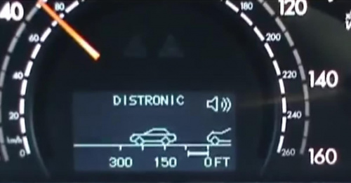
Activation – W220 after 2004-06-01
For the Activation, David Prokity recommends;
- Replace the main factory software with new. The programming that brings the car to life was basically reinstalled with Distronic added.
- Have the code number (219) added to the data card, which is the build card ie the factory record of the items installed like Parktronics, TPMS, Voice Command, NAV etc.
- Have SCN code added to the Engine Management System.
You can also change engine control unit coding using Vediamo. It is not nessesery to change data card and perform online SCN Coding.
Calibration – Distronic
It is essential that the three radar beams of the Distronic can detect and recognise vehicles at the correct distances and positions on the road.
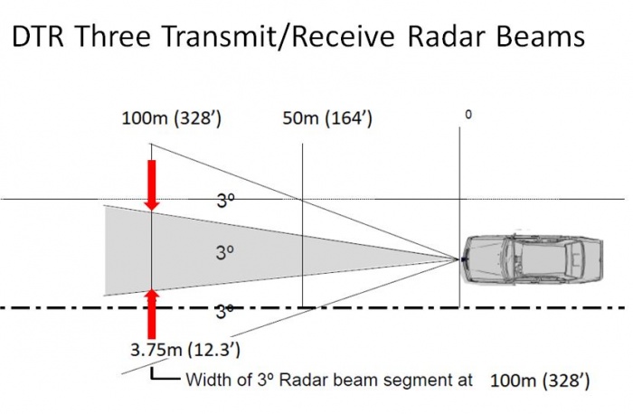
The Radar Sensor Unit has three screws for adjusting the transmit angle.
It is preferable that the Distronic calibration and alignment be performed by a M-B expert using a special alignment tool.
See section Special Tools Distronic (DTR) Calibration Tool
One BenzWorld member posted "To aim the unit you just turn the mounting screws all the way in by hand . Do not torque just bottom them out. Back out 1½ turns and you are set. Drive around and over time you will see if you need to adjust. It is really that easy and no expensive equipment is required."
Also checkout
AR30.30-p-1000R: Check/adjust sensor setting of Distronic (DTR).
AR30.30-p-1010Q: Remove/install Distronic sensor (DTR).
Notes on Using – Distronic
DTR will NOT engage:
- For up to two minutes after engine start-up (This is the initialization or self test phase.)
- Vehicle speed < 25 Km/h or mph
- With Parking Brake activated
- With ESP manually switched OFF
- If gear selector is NOT in position 'D'
DTR may be controlled in the same manner as the Cruise Control or Speed Limiter.
DTR will switch off automatically for the same reasons as Cruise Control.
The Distance potentiometer on the Centre Console regulates the DTR "following interval", or distance to the lead vehicle, from 1 to 2 secs.
DTR screen can be displayed in the instrument cluster while driving without engaging cruise control (the word DISTRONIC doesn’t appear).
DTR audible warnings are active without cruise control engagement, unless switched off by driver using the DTR switch on the Centre Console.
DTR will not apply the brakes to slow the vehicle while driver is using the accelerator to exceed the DTR speed setting.
If DTR display shows “ ---“ instead of the current vehicle speed may be due to dirt, snow or ice build up on the radar sensor or road mist, heavy rain or fog which can reduce radar signals enough to cause difficulty in detecting vehicles ahead.
