WIS 80.57 Drive Authorization System: Difference between revisions
(→DIY Solution No. 1: fixed youtube url) |
Ricebubbles (talk | contribs) (→Investigation of Issue - Remote Control Key Will Not Rotate/Work/Turn in EIS (EZS): Added test results) |
||
| (12 intermediate revisions by 2 users not shown) | |||
| Line 1: | Line 1: | ||
== | ==Description - Drive Authorization System== | ||
===Function - Drive Authorization System=== | |||
All Mercedes-Benz vehicles manufactured since about the year 2000 use a Drive Authorization System (DAS) to electronically validate the vehicle’s key. Each key fob for this system contains an EEPROM chip that stores a fixed serial number and a rolling code. Each time the key is used in the ignition switch, DAS reads both the fixed serial number and the rolling code. These values are compared to known valid values stored in DAS. If a match is found, the ECM will allow the engine to start and run, and DAS will write a new “randomized” rolling code to the key fob’s EEPROM. If the key fails validation, even if it is mechanically able to turn the ignition switch, the ECM will prevent the engine form running. | |||
Every Mercedes-Benz vehicle has a record in FDOK (M-B’s worldwide database that contains all information about every M-B ever built), including the assignment of all electronic key codes for all vehicles using DAS. | |||
When the record is created for a new vehicle, a set of unique key serial numbers is assigned and stored in FDOK. Only certain authorized employees at authorized PDC PDC’s (Parts Distribution Centers) have access to this information. Authorized PDC’s stock virgin key transponders and have special equipment to program them with valid serial numbers from FDOK. Keys are programmed when a key set is ordered for a new vehicle or an additional or replacement key is ordered for an existing vehicle. Only a factory or an authorized service center can order keys. For existing vehicles, the service center is required to verify that the customer ordering a key is in fact the owner of the vehicle in question. Examining the customer’s photo ID and the vehicle’s registration receipt generally satisfies this. | |||
For new factory vehicles, there is an operation that performs the initial programming of DAS to introduce it to its assigned key set. This loads all the pre-defined key serial numbers into DAS as defined in FDOK. Even though not all keys physically exist, all possible key ID’s for that vehicle are loaded. This is performed in different ways depending on which version of DAS the vehicle uses. Once performed, there is a programming process that irreversibly locks this data into DAS. Once married to a key set, DAS will only recognize keys in that set. Officially, there is no way to reverse this process and introduce a new key set to DAS, nor is there a way to alter any of the individual key ID’s know to DAS. | |||
==Batteries== | For all versions of DAS, there is no battery required for the key. The battery in the key fob is used only to power the Remote Control Locking (RCL) functions. The power for the DAS functions comes from an electronic coil mounted in the ignition switch housing that supplies inductive current to the circuitry in the key fob. For some early vehicles, this coil is also used to transmit and receive radio frequency signals for reading and writing the key’s EEPROM. For later vehicles, the transfer of data between the EIS and the fob’s EEPROM is performed via an infrared signal. Also, since there is no mechanical blade to unlock the ignition switch, the release of both the ignition switch and the steering column lock is performed electronically once DAS validate the key through the infrared data exchange. | ||
===OEM Keys - Drive Authorization System=== | |||
DAS has a maximum of 24 keys per vehicle, however only 8 can be active at a time. Basically for each key number, there are three key segments. The valid key numbers and segments are programmed into the virgin ESL, EIS and ECM using a special green-colored workshop key. As delivered, the vehicle will have two keys using key number 1, segment 1 and key number 2, segment 1 (some models were delivered with three keys, the third one using key number 3, segment number 1). | |||
Typical OEM as delivered vehicle with two keys per vehicle. | |||
*Key Number 1 | |||
** Segment 1 | |||
** Segment 2 | |||
*Key Number 2 | |||
** Segment 1 | |||
** Segment 2 | |||
Typical OEM as delivered vehicle with three keys per vehicle. | |||
*Key Number 1 | |||
** Segment 1 | |||
** Segment 2 | |||
*Key Number 2 | |||
** Segment 1 | |||
** Segment 2 | |||
*Key Number 3 | |||
** Segment 1 | |||
===Additional Keys - Drive Authorization System=== | |||
When a new key is ordered, the PDC determines which key number and segment to supply based on whether the key is a replacement for a lost one or and additional spare key. | |||
If an additional spare key is requested, then the PDC will create it as the next unused key number, segment 1. If a replacement key is requested, the technician must determine which key number was lost and order its replacement. The PDC will create the replacement with the next unused segment number for that same key number. When the replacement key is first used in the vehicle, DAS will disable the use of the key using the same key number and the previous segment. For example, if key number 2 is lost, the technician orders a replacement for key number 2 and the PDC supplies key number 2, segment 2. When this new key is used in the vehicle, this will disable key number 2, segment 1. Even if that lost key is found, it will no longer operate the vehicle. If key number 2 is lost again, the technician again orders a replacement for key number 2 and the PDC supplies key number 2, segment 3, which disables key number 2, segment number 2. If key number 2 is lost again, the PDC will supply a key with the next unused key number, segment 1, and the technician will be instructed to disable key number 2 completely using a Hand Held Tester via the OBDII port and the vehilce’s CAN. Note that RCL functions are tied to DAS so no additional programming is necessary to completely disable the remote locking/unlocking ability of a lost key. | |||
===Everything you ever wanted to know about the Drive Authorisation System (DAS), EIS and Keys=== | |||
Information gathered from various official MBZ sources, included technical documentation, service documents, and even authorized technicians and factory personnel, by BenzWorld Member rudeney. | |||
http://www.benzworld.org/forums/w163-m-class/1245088-everything-you-always-wanted-know-about.html | |||
==Remote Control Key== | |||
===Description - Remote Control Key=== | |||
The four main components of the Remote Control Key (A8/1) are the key fob case, electronic printed circuit board, the battery holder with fob lid and with two 3V CR2025 button type batteries, and the emergency mechanical key. | |||
[[File:Button Side of a W220 Remote Control Key.jpg|300px|center]] | |||
[[File:Reverse Side of a W220 Remote Control Key.jpg|300px|center]] | |||
The Remote Control Key (A8/1) emits radio frequency (RF) (In Australia 315 MHz) frequency modulated (FM) signals to operate the remote control functions of unlocking, locking, and boot/trunk opening. The two internal batteries in the key fob are used to power these functions. If these batteries are weak or flat, the key will not unlock the doors or boot/trunk. A emergency mechanical key is stored inside the key fob and is provided in the event of this situation occurring. | |||
The Remote Control Key also emits infra red (IR) signals to operate the convenience opening and closing feature. The IR signals are received by either IR sensor built into the two front door handles. The key needs to be pointing at the handle and within a few metres for the function to work. Better range is achieved if the receiving door handle is not in direct sunlight. The two internal batteries in the key fob are used to power the IR emitter for this function | |||
===How It Works - Remote Control Key and EIS=== | |||
When a Remote Control Key (or a finger for that matter) is inserted in the electronic ignition switch (EIS or EZS) control unit (ignition lock) (N73), it operates a switch which activates an AC generator inside the ignition lock. This generator produces a high frequency (118KHz) sine wave which is inductively coupled to a small coil in the tip of the key fob. | |||
[[File:Induction Coil on a Remote Control Key PCB.jpg|300px|center]] | |||
The AC voltage produced in the coil is rectified and the resulting DC voltage is used to power the Remote Control Key ignition functions. (The induced DC voltage was measured as 7.6V.) Using a separate inductive power supply very cleverly avoids reliance on the Remote Control Key batteries and ensures the Remote Control Key will operate the ignition even if it has internal flat or weak batteries. | |||
[[File:Induction Coils on the Barrel of the EIS.jpg|500px|center]] | |||
Once powered by the Induction Power Generator the Remote Control Key emits IR signals to, and receives IR signals from, the Drive Authorisation System (DAS) in the Electronic Ignition/Starter Switch (EIS) control module (N73). Start-up is enabled only after the transmitter key (A8/1) is identified by the encrypted data exchange between the | |||
* EIS control unit (N73) and the | |||
* ME-SFI control unit (N3/10) (with gasoline engine). | |||
If the identification of the transmitter key (A8/1) is valid, the rotary lock of the EIS control unit (N73) is enabled. The transmitter key (A8/1) can now be turned. Once the correct code is recognised, the EIS allows the initial start procedures to commence, viz; | |||
* rotary lock in EIS released, which allows the key to be turned in the lock to positions 1, 2 and 3, thus starting the car. | |||
* steering wheel resumes it’s operating position (if this function has been previously activated), | |||
* engine electric suction fan initiates, | |||
* engine control module initiates, | |||
* Automatic Climate Control (ACC) initiates, | |||
* COMAND system initiates, | |||
* gear selector lever lockout mechanism releases, | |||
* any stored values for parameters such as seat and mirror positions, ACC settings, and COMAND settings etc. which are associated with this particular key are initiated (if this function has been previously activated). | |||
When a non-recognised key is used the EIS Inductive Power Supply only operates for about 3 to 4 seconds after the key has been inserted into the Ignition Lock. When the key is not recognised, the Inductive Power Supply reverts to zero output for about 30 seconds when it generates another short burst of AC power in an attempt to read the key. I did not establish how many times it continues to do this before cancelling. | |||
When a key is used that is recognised by the EIS, the Inductive Power Supply operates continuously until the key is removed. | |||
Note the mechanical lock system in the EIS also prevents the Remote Control Key from being turned back to position 0 (Locked) and withdrawn from the EIS Ignition Lock unless the gear selector lever is in ‘P’ or Park. | |||
===Tip for Using Mechanical Key=== | |||
Extract the Emergency Mechanical Key from the Remote Control Key Fob and after inserting into the door or boot lock, turn it all the way to the left (CCW). | |||
===Weak Batteries in Remote Control Key Fob=== | |||
The Remote Control Key Fob functions may be affected by weak batteries in the key. If your key will not lock and unlock the car from 10m (30ft) or more, your batteries are weak and that will compromise the strength of the infrared (IR) beam. Try changing the batteries in the key before you go to more complicated (and expensive) efforts at restoring the function. | |||
If the key will not turn in the ignition lock it is NOT caused by weak batteries in the key as the key electronics are powered inductively from the EIS Control Module when inserted into the ignition. See below for solutions to malfunctioning EIS. | |||
====Part Numbers - Remote Control Key Fob Batteries==== | |||
: 2003 Update S500L Remote Key Fob has two batteries ie CR2025 x 2 | : 2003 Update S500L Remote Key Fob has two batteries ie CR2025 x 2 | ||
: 2005 S500 Keyless Go Fob has only 1 Battery #2025 | : 2005 S500 Keyless Go Fob has only 1 Battery #2025 | ||
==How To Change Batteries - Remote Key Fob== | ====How To Change Batteries - Remote Control Key Fob==== | ||
http://www.mbworld.org/forums/audio-...-pictures.html | http://www.mbworld.org/forums/audio-...-pictures.html | ||
== | ===Programming - Remote Control Key Fob=== | ||
This video instruction is suitable for Car Key Master: CKM-100(PC Version) and CKM-200(Handhold Version), also it is suitable for Digimaster 3. | |||
{{#ev:youtube|https://www.youtube.com/watch?v=nKTab4Yxeds|320|left|Part 1|frame}} | |||
<br clear=all> | |||
===Issue=== | {{#ev:youtube|https://www.youtube.com/watch?v=8TZh9p9sIuw|320|left|Part 2|frame}} | ||
<br clear=all> | |||
==Electronic Ignition/Starter Switch (EIS or EZS) Control Module (N73)== | |||
===Common Issue - Remote Control Key Will Not Rotate/Work/Turn in EIS (EZS)=== | |||
Normally after inserting the correct Remote Control Key in the ignition lock (Electronic Ignition/Starter Switch (EIS) control module (N73)) it will turn instantly to position 1 (accessories), 2 (ignition on) and position 3 (engine start). However it seems that a common fault in the W220 occurs whereby the correct key will unlock the doors but once inserted in the ignition will not rotate and appears frozen. The vehicle cannot be started while the key will not turn. | Normally after inserting the correct Remote Control Key in the ignition lock (Electronic Ignition/Starter Switch (EIS) control module (N73)) it will turn instantly to position 1 (accessories), 2 (ignition on) and position 3 (engine start). However it seems that a common fault in the W220 occurs whereby the correct key will unlock the doors but once inserted in the ignition will not rotate and appears frozen. The vehicle cannot be started while the key will not turn. | ||
===Temporary Solution=== | ===Temporary Solution for Issue - Remote Control Key Will Not Rotate/Work/Turn in EIS (EZS)=== | ||
The frozen key often happens intermittently causing huge frustration when out travelling. If you are lucky it may eventually start working again after continually trying and waiting twenty minutes. It is presumed that the EIS warms up slightly during this process. | The frozen key often happens intermittently causing huge frustration when out travelling. If you are lucky it may eventually start working again after continually trying and waiting twenty minutes. It is presumed that the EIS warms up slightly during this process. | ||
| Line 28: | Line 130: | ||
Some owners have successfully used hair driers and electrical heaters to pre-warm the area around the ignition switch (EIS) to get the car started. Of course this is not a permanent fix but may get you out of immediate trouble. | Some owners have successfully used hair driers and electrical heaters to pre-warm the area around the ignition switch (EIS) to get the car started. Of course this is not a permanent fix but may get you out of immediate trouble. | ||
=== | ===Possible Failure Mechanism for Issue - Remote Control Key Will Not Rotate/Work/Turn in EIS (EZS)=== | ||
It is now apparent, thanks to several BenzWorld Members and especially YouTube Poster John Kennedy, that one of the microprocessor chips on the EIS becomes sensitive to cold temperatures. Warming this particular chip temporarily solves the problem until it cools down sufficiently again. | It is now apparent, thanks to several BenzWorld Members and especially YouTube Poster John Kennedy, that one of the microprocessor chips on the EIS becomes sensitive to cold temperatures. Warming this particular chip temporarily solves the problem until it cools down sufficiently again. A DIY fix for this is available below. | ||
Of course it may be that it is not the actual chip that is sensitive to cold but one or more of the solder joints connecting the chip to the board may have developed hair line cracks which open when cold and close when warmed. | Of course it may be that it is not the actual chip that is sensitive to cold but one or more of the solder joints connecting the chip to the board may have developed hair line cracks which open when cold and close when warmed. | ||
===Investigation=== | ===Investigation of Issue - Remote Control Key Will Not Rotate/Work/Turn in EIS (EZS)=== | ||
====DIY Fix #1==== | |||
The link shows one investigation with the bottom line that it was not a DIY solution. ('''Later note:''' YouTube Poster John Kennedy shows that a DIY fix is now possible.) | The link shows one investigation with the bottom line that it was not a DIY solution. ('''Later note:''' YouTube Poster John Kennedy shows that a DIY fix is now possible.) | ||
* Parts of a W220 Remote Control Key | * Parts of a W220 Remote Control Key | ||
| Line 46: | Line 148: | ||
http://www.benzworld.org/forums/w220-s-class/1300215-cold-weather-electronic-key-problems-5.html | http://www.benzworld.org/forums/w220-s-class/1300215-cold-weather-electronic-key-problems-5.html | ||
=== | ====DIY Testing EIS Induction Power Generator Output==== | ||
In order to investigate the performance of the Induction Power Generator the author decided to measure the AC signal produced by the ignition lock (Electronic Ignition/Starter Switch (EIS) control module (N73)). | |||
=====Construction of Dummy Test Key===== | |||
Using parts from an old dismantled electrical transformer, I constructed a small coil on the end of an old small paint brush. I ground the end of the paint brush down to a cylinder of about 3mm diameter. I added a single piece of scrap transformer metal to the wooden cylinder to act as a core and bound both together with masking tape. This became the former for the coil and provided a nice winding surface. I wound approximately a thousand turns of 1.1mm diameter enamel insulated copper wire onto the former and soldered some insulated flexible wires for the test connections. | |||
[[File:Key Fob Test Induction Coil.jpg|500px|center]] | |||
The exposed coil and connections were wrapped in masking tape and were inserted into an old empty key fob thus making a dummy test key. | |||
[[File:Test Induction Coil Inserted Into an Empty Key Fob.jpg|500px|center]] | |||
=====Testing Using Dummy Test Key===== | |||
The AC voltage produced in the coil in my Dummy Test Key by the EIS Induction Power Generator was measured with a Digital Volt Meter (DVM) and a Cathode Ray Oscilloscope (CRO) in several M-B vehicles including my W220 S500L. The DVM readings proved to be unreliable, most likely due to the high frequency of the signals exceeding the DVM’s capability. The DVM readings were not analysed. | |||
Note the actual voltages as measured with the Dummy Test Key are completely arbitrary and are dependent on the number of turns wound on the Dummy Test Key coil. They are useful for comparison purposes only. | |||
'''DVM Reading Dummy Test Key AC Output in W220 S500L''' | |||
[[File:DVM Reading Dummy Test Key AC Output in W220 S500L.jpg|400px|center]] | |||
'''CRO Reading Dummy Test Key AC Output in W220 S500L''' | |||
CRO Scale: 1V/division with 10x Probe = 10V/division and 5µs/division | |||
[[File:CRO Reading Dummy Test Key AC Output in W220 S500L.jpg|400px|center]] | |||
{| class="wikitable" style="margin: auto;" | |||
|+Summary of Test Results Using Dummy Test Key | |||
|- | |||
!style="text-align:center;"| | |||
!W220 2003 Update S500L | |||
|- | |||
|CRO AC Amplitude Peak to Peak | |||
|63V p-p | |||
|- | |||
|Calculated CRO AC Amplitude | |||
|22Vrms | |||
|- | |||
|CRO AC Timing Period | |||
|8.5µs | |||
|- | |||
|Calculated CRO AC Frequency | |||
|118KHz | |||
|} | |||
=====Comparison of Test Results for W204 C220, W211 E320, W209 CLK200K and W220 S500L===== | |||
Note the actual voltages as measured are completely arbitrary and are dependent on the number of turns wound on the Dummy Test Key coil. They are useful for comparison purposes only. | |||
The CRO Scale was: 1V/division with 10x Probe = 10V/division and 5µs/division. | |||
[[File:Comparison of CRO Test Results with Dummy Key C220 E320 CLK200 S500.JPG|600px|center]] | |||
{| class="wikitable" style="margin: auto;" | |||
|+Summary of Test Results Using Dummy Test Key | |||
|- | |||
!style="text-align:center;"| | |||
!W204 2008 C220 CDI | |||
!W211 2004 E320 | |||
!W209 2005 CLK200K | |||
!W220 2003 Update S500L | |||
|- | |||
|CRO AC Amplitude Peak to Peak | |||
|85Vp-p | |||
|85Vp-p | |||
|87Vp-p | |||
|63Vp-p | |||
|- | |||
|Calculated CRO AC Amplitude | |||
|30Vrms | |||
|30Vrms | |||
|31Vrms | |||
|22Vrms | |||
|- | |||
|CRO AC Timing Period | |||
|8.5µs | |||
|8.5µs | |||
|8.5µs | |||
|8.5µs | |||
|- | |||
|Calculated CRO AC Frequency | |||
|118KHz | |||
|118KHz | |||
|118KHz | |||
|118KHz | |||
|- | |||
|Normalised Comparison | |||
|97% | |||
|97% | |||
|100% | |||
|71% | |||
|} | |||
=====Test Conclusion===== | |||
The Dummy Test Key induced coil voltages as measured by the CRO were very stable and consistent. The W220 Induction Power Generator output is only about 71% when compared to three other equal vintage Mercedes Benz vehicles. | |||
It seems that the EIS Induction Power Generator output in the W220 was lower than the comparison vehicles. It was thought that this could be a high resistance in the fuses, fuse connections or cable connectors in the appropriate EIS supply lines or it could also be due to a faulty voltage regulator in the supply to the EIS Induction Power Generator circuit. | |||
To try to determine exactly what determined the lower voltage the following tests were carried out. | |||
=====Test of EIS Fuses===== | |||
'''EIS Wiring Diagram''' | |||
[[File:W220 EIS Wiring Diagram.jpg|400px|center]] | |||
The voltage drop across f78/7.5A (FB Cockpit Left (RHD)) was measured with the key out, and key in. | |||
{| class="wikitable" style="margin: auto;" | |||
|+Voltage Drop Across f78/7.5A | |||
|- | |||
!style="text-align:center;"| | |||
!Battery Side of f78 | |||
!EIS Side of f78 | |||
|- | |||
|Key Out | |||
|12.69V | |||
|12.69V | |||
|- | |||
|Key In and Not Operational | |||
|12.60V | |||
|12.58V | |||
|- | |||
|Key In and Operational | |||
|12.54V | |||
|12.52V | |||
|} | |||
The voltage drop across f78 seems reasonable. The voltage drops across X4/10 f2/60A and connectors Z4/3 and W36/2 were not measured. | |||
=====Test of Induced Voltages In Actual OEM Remote Control Key===== | |||
The tests conducted with the Dummy Test Key were useful to establish that the EIS was producing an AC frequency in the Induction Power Supply and that it was being inductively coupled into a Remote Control Key once inserted into the lock. The Dummy Test Key also provided useful comparison results between similar vintage Mercedes vehicles, albeit not exactly the same model. | |||
These previous Dummy Test Key tests were ‘open circuit’ tests, ie the coil had no load connected to it and any induced voltage thus produced no current. | |||
The next test aimed to measure the voltage induced in an actual Remote Control Key by the EIS once the key is inserted into the lock. This type of test is a ‘fully loaded’ test, ie the internal coil is connected to it’s normal circuits and thus any induced voltage will produce current and activate the circuits. It is a more meaningful test but more difficult to execute. It requires some very careful and fiddly soldering and should only be undertaken by someone with considerable electronic experience. Things to avoid are damage caused by electrostatic voltages, excess heat and rough or splattered soldering. | |||
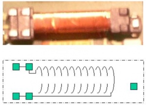
As explained previously the EIS generates a 118KHz sine wave which is inductively picked up in a small coil in the tip of the Remote Control Key fob. The coil is connected to the two tabs at the left edge of the coil in the next figure. The tab at the right end of the coil is not connected and is just for fastening that end of the coil. | |||
[[File:W220 Remote Control Key Induction Coil Wiring Diagram.jpg|300px|center]] | |||
The induction coil connections were traced as far as possible. Some tracks disappear under surface mount components, and the coil is connected to a diode and what I suspect is a zener diode resulting in a roughly regulated half wave DC power supply. The voltage produced cannot exceed the maximum voltage rating marked on the large electrolytic capacitor, the large yellow component shown just below the coil in the next figure. | |||
[[File:Battery Side of Remote Control Key PCB Showing Induction Coil.jpg|300px|center]] | |||
The capacitor has a value of 47μF 10V and is used to store the DC voltage produced. It’s time constant is many minutes, ie it holds the voltage charge and powers the key electronics long after the EIS has stopped generating the AC frequency. | |||
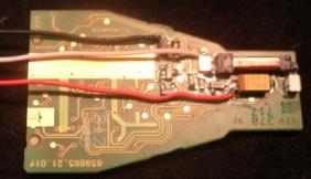
Two wires were soldered across the coil (white (AC) and black (0V)) and also one wire (red (+V)) on to the (red band) end of the capacitor. The modified key could still be inserted into the key fob but without the battery holder and batteries. These were not needed anyway. | |||
[[File:Battery Side of Remote Control Key PCB Showing Test Wires Soldered Across the Induction Coil and the Storage Capacitor.jpg|300px|center]] | |||
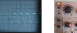
'''Measurement of DC Voltage Generated in S500L OEM Remote Control Key Electronics''' | |||
Initial test was performed on a 2003 W220 S500L. | |||
[[File:Test of OEM Remote Key Coil Output on W220 S500L.jpg|500px|center]] | |||
[[File:Test DVM Reading S500L OEM Remote Control Key DC Output in W220 S500L.jpg|200px|center]] | |||
CRO Scale: 1V/division with 10x Probe = 10V/division and 5µs/division | |||
[[File:Test CRO Reading S500L OEM Remote Control Key AC Output in W220 S500L.jpg|500px|center]] | |||
These DC voltage tests were repeated on a 2008 W204 C220 CDI for comparison. | |||
'''Comparison of W204 C220 (Left) and W220 S500L (Right) with CRO on Same Scale''' | |||
CRO Scale: 1V/division with 10x Probe = 10V/division and 5µs/division | |||
[[File:Test Comparison of W204 C220 (Left) and W220 S500L (Right) with CRO on same scale.jpg|300px|center]] | |||
The amplitudes of both DC voltages were near enough the same at 7.60V and 7.50V respectively. | |||
===Replacing EIS Module=== | |||
====How To Remove - EIS Module==== | |||
Turns out it was an easy job for a RHD car (probably much easier than a LHD car) to remove the EIS. | |||
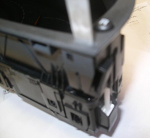
The first step was to remove the Glove Box so that the two nuts securing the Burred Walnut strip across the dash could be removed. Then the Walnut strip was removed making it easier to extract the Instrument Cluster. | |||
For a RHD car the Instrument Cluster is removed using special tools or easy manufactured homemade ones fashioned out of 1mm thick sheet aluminium. See Instrument Cluster Repair Tool Kit here [http://w220.ee/Special_Tools#Instrument_Cluster_Repair_Tool_Kit] | |||
When inserted into the slots on each side of the Instrument Cluster they release plastic retaining clips. The left hand clip took much persuading but eventually released. | |||
[[File:Retaining Clip in Instrument Cluster.jpg|300px|center]] | |||
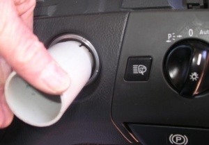
The EIS bezel is easily unscrewed using a special tool. See Electronic Ignition Switch (EIS) here [http://w220.ee/Special_Tools#Electronic_Ignition_Switch_.28EIS.29] | |||
[[File:Bezel Unscrewing Tool Inserted in EIS.jpg|300px|center]] | |||
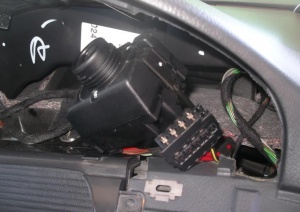
Then it is an easy matter to reach inside and extract the EIS to the point where the connectors canbe removed. The mechanical rod which activates the Transmission Lock was also disconnected. | |||
[[File:Connectors Removed From EIS.jpg|300px|center]] | |||
[[File:Three Views of W220 EIS.JPG|600px|center]] | |||
====M-B Solution - Replacing EIS Module==== | |||
The easiest but extremely expensive solution is to replace the EIS with a new one. It will cost over $3,000 and requires reprogramming of the new EIS to match the vehicle. As this is deemed a safety/security issue it can only be done by an authorized M-B agent. | The easiest but extremely expensive solution is to replace the EIS with a new one. It will cost over $3,000 and requires reprogramming of the new EIS to match the vehicle. As this is deemed a safety/security issue it can only be done by an authorized M-B agent. | ||
===DIY Solution No. 1=== | ====DIY Solution No. 1 - Less Expensive Solution for Complete EIS Replacement==== | ||
In Australia it is not necessarily a Dealer only option any more. | |||
On line parts supplier [http://www.genuineautoparts.com Genuine Auto Parts] will sell an EIS to the public for about AU$625 and Mercedes-Benz will supply a green (workshop) key with a AU$500 deposit, refunded on return of the key. | |||
====DIY Solution No. 2 - Replacing EIS Microprocessors==== | |||
With a huge acknowledgement to YouTube Poster John Kennedy (and BenzWorld Member pinkster, Dean, for discovering the video) whose excellent diagnosis shown in the video referenced below positively demonstrates a faulty microprocessor which caused his issue. | With a huge acknowledgement to YouTube Poster John Kennedy (and BenzWorld Member pinkster, Dean, for discovering the video) whose excellent diagnosis shown in the video referenced below positively demonstrates a faulty microprocessor which caused his issue. | ||
| Line 68: | Line 368: | ||
<br clear=all> | <br clear=all> | ||
====Warning==== | =====Warning===== | ||
Be aware that in other cases it may not be the microprocessor chip shown in this article that fails but could be other components or even the solder joints themselves so some diagnosis as per the video will be necessary to thoroughly isolate the faulty component or item. | Be aware that in other cases it may not be the microprocessor chip shown in this article that fails but could be other components or even the solder joints themselves so some diagnosis as per the video will be necessary to thoroughly isolate the faulty component or item. | ||
| Line 78: | Line 378: | ||
Any comments on how the reprogramming is done would be appreciated, especially by some one who has successfully completed the DIY fix of an EIS. | Any comments on how the reprogramming is done would be appreciated, especially by some one who has successfully completed the DIY fix of an EIS. | ||
====Part Numbers==== | =====Part Numbers - EIS Microprocessors===== | ||
The part numbers for the microprocessors in the EIS from a 2003 (Update) W220 S500L are: | The part numbers for the microprocessors in the EIS from a 2003 (Update) W220 S500L are: | ||
| Line 102: | Line 402: | ||
[[File:W220 EIS Microprocessor 02.JPG|400px|center]] | [[File:W220 EIS Microprocessor 02.JPG|400px|center]] | ||
====Parts Availability==== | =====Parts Availability - EIS Microprocessors===== | ||
With thanks to BenzWorld Member pinkster, Dean these microprocessors are available for about US$30 posted from this source. | With thanks to BenzWorld Member pinkster, Dean these microprocessors are available for about US$30 posted from this source. | ||
[http://www.aliexpress.com/item/SC510108CFU-4J74Y-automotive-chips-quality-assurance/1956927024.html?aff_platform=aaf&sk=bm2aeAra%3A&cpt=1436314289549&af=3193630&cn=002&cv=11032041&dp=ibu0fvj867000b1w008sc&dl_target_url=http%3A%2F%2Fwww.aliexpress.com%2Fitem%2FSC510108CFU-4J74Y-automotive-chips-quality-assurance%2F1956927024.html&PID=3193630&URL=http%3A%2F%2Fwww.aliexpress.com%2Fitem%2FSC510108CFU-4J74Y-automotive-chips-quality-assurance%2F1956927024.html&aff_trace_key=42846488950678656] | [http://www.aliexpress.com/item/SC510108CFU-4J74Y-automotive-chips-quality-assurance/1956927024.html?aff_platform=aaf&sk=bm2aeAra%3A&cpt=1436314289549&af=3193630&cn=002&cv=11032041&dp=ibu0fvj867000b1w008sc&dl_target_url=http%3A%2F%2Fwww.aliexpress.com%2Fitem%2FSC510108CFU-4J74Y-automotive-chips-quality-assurance%2F1956927024.html&PID=3193630&URL=http%3A%2F%2Fwww.aliexpress.com%2Fitem%2FSC510108CFU-4J74Y-automotive-chips-quality-assurance%2F1956927024.html&aff_trace_key=42846488950678656] | ||
===DIY Solution No. | ====DIY Solution No. 3 - Replacement EIS via eBay==== | ||
Australian BenzWorld Member iSteve reported that he purchased a replacement EIS with the same part number as his on eBay from the USA. | Australian BenzWorld Member iSteve reported that he purchased a replacement EIS with the same part number as his on eBay from the USA. | ||
He was advised by his Indie that the US uses the same key frequency as Australia and hence the | He was advised by his Indie that the US uses the same key frequency as Australia and hence the USA sourced EIS would be compatible with the Australian standards. | ||
Initially the Indie only "cloned" one EPROM which resulted in some errors such as; | Initially the Indie only "cloned" one EPROM which resulted in some errors such as; | ||
| Line 124: | Line 424: | ||
Reference [http://www.benzworld.org/forums/w220-s-class/1300215-cold-weather-electronic-key-problems-8.html] | Reference [http://www.benzworld.org/forums/w220-s-class/1300215-cold-weather-electronic-key-problems-8.html] | ||
===DIY Solution No. | ====DIY Solution No. 4 - "The Ultimate EIS Repair Guide"==== | ||
MHH Auto senior member 'bawarek' has posted an excellent although very technical article titled, "The ultimate Mercedes EIS repair guide". | MHH Auto senior member 'bawarek' has posted an excellent although very technical article titled, "The ultimate Mercedes EIS repair guide". | ||
See http://mhhauto.com/Thread-The-ultimate-Mercedes-EIS-repair-guide | See http://mhhauto.com/Thread-The-ultimate-Mercedes-EIS-repair-guide | ||
== | ===Internal Components - EIS Module=== | ||
Here are some of the internal components of the IES and their functions. | |||
* Motorola SC510108CFUis a 64pin microprocessor. (There are two of these in my EIS.) (I could not find a pin configuration diagram identifying pin functions.) | |||
* PCA82C250 is a 8 pin Philips Can Controller Interface. It provides differential transmit and receive to the CAN-C (Engine) bus. | |||
* TJA1054 is a 14 pin Philips Fault-tolerant CAN Transceiver. . It provides differential transmit and receive to the CAN-B (Interior) bus. | |||
* 42760V5 is a 5 pin 5V Regulator in a TO252-5 case. | |||
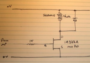
* IR322A is a hexfet power mosfet in a TO252-AA case. | |||
===Connector Pin Diagram - EIS Module=== | |||
Here are the pin diagrams for the connectors. | |||
[[File:Rear View Showing Fixed Connectors for EIS.jpg|400px|center]] | |||
Matching rear view showing fixed connectors. | |||
[[File:Rear View of Fixed Connectors for EIS.jpg|300px|center]] | |||
Circuit Diagram for ‘A’ Connector for EIS. | |||
[[File:Circuit Diagram for ‘A’ Connector for EIS.jpg|400px|center]] | |||
Also shown for interest is the circuit diagram for the EIS Lock Solenoid. A signal from one of the microprocessors turns on the hex mosfet which activates the solenoid and allows the key to rotate in the EIS. | |||
[[File:Circuit Diagram for EIS Lock Solenoid.jpg|300px|center]] | |||
Latest revision as of 08:40, 12 June 2016
Description - Drive Authorization System
Function - Drive Authorization System
All Mercedes-Benz vehicles manufactured since about the year 2000 use a Drive Authorization System (DAS) to electronically validate the vehicle’s key. Each key fob for this system contains an EEPROM chip that stores a fixed serial number and a rolling code. Each time the key is used in the ignition switch, DAS reads both the fixed serial number and the rolling code. These values are compared to known valid values stored in DAS. If a match is found, the ECM will allow the engine to start and run, and DAS will write a new “randomized” rolling code to the key fob’s EEPROM. If the key fails validation, even if it is mechanically able to turn the ignition switch, the ECM will prevent the engine form running.
Every Mercedes-Benz vehicle has a record in FDOK (M-B’s worldwide database that contains all information about every M-B ever built), including the assignment of all electronic key codes for all vehicles using DAS.
When the record is created for a new vehicle, a set of unique key serial numbers is assigned and stored in FDOK. Only certain authorized employees at authorized PDC PDC’s (Parts Distribution Centers) have access to this information. Authorized PDC’s stock virgin key transponders and have special equipment to program them with valid serial numbers from FDOK. Keys are programmed when a key set is ordered for a new vehicle or an additional or replacement key is ordered for an existing vehicle. Only a factory or an authorized service center can order keys. For existing vehicles, the service center is required to verify that the customer ordering a key is in fact the owner of the vehicle in question. Examining the customer’s photo ID and the vehicle’s registration receipt generally satisfies this.
For new factory vehicles, there is an operation that performs the initial programming of DAS to introduce it to its assigned key set. This loads all the pre-defined key serial numbers into DAS as defined in FDOK. Even though not all keys physically exist, all possible key ID’s for that vehicle are loaded. This is performed in different ways depending on which version of DAS the vehicle uses. Once performed, there is a programming process that irreversibly locks this data into DAS. Once married to a key set, DAS will only recognize keys in that set. Officially, there is no way to reverse this process and introduce a new key set to DAS, nor is there a way to alter any of the individual key ID’s know to DAS.
For all versions of DAS, there is no battery required for the key. The battery in the key fob is used only to power the Remote Control Locking (RCL) functions. The power for the DAS functions comes from an electronic coil mounted in the ignition switch housing that supplies inductive current to the circuitry in the key fob. For some early vehicles, this coil is also used to transmit and receive radio frequency signals for reading and writing the key’s EEPROM. For later vehicles, the transfer of data between the EIS and the fob’s EEPROM is performed via an infrared signal. Also, since there is no mechanical blade to unlock the ignition switch, the release of both the ignition switch and the steering column lock is performed electronically once DAS validate the key through the infrared data exchange.
OEM Keys - Drive Authorization System
DAS has a maximum of 24 keys per vehicle, however only 8 can be active at a time. Basically for each key number, there are three key segments. The valid key numbers and segments are programmed into the virgin ESL, EIS and ECM using a special green-colored workshop key. As delivered, the vehicle will have two keys using key number 1, segment 1 and key number 2, segment 1 (some models were delivered with three keys, the third one using key number 3, segment number 1).
Typical OEM as delivered vehicle with two keys per vehicle.
- Key Number 1
- Segment 1
- Segment 2
- Key Number 2
- Segment 1
- Segment 2
Typical OEM as delivered vehicle with three keys per vehicle.
- Key Number 1
- Segment 1
- Segment 2
- Key Number 2
- Segment 1
- Segment 2
- Key Number 3
- Segment 1
Additional Keys - Drive Authorization System
When a new key is ordered, the PDC determines which key number and segment to supply based on whether the key is a replacement for a lost one or and additional spare key.
If an additional spare key is requested, then the PDC will create it as the next unused key number, segment 1. If a replacement key is requested, the technician must determine which key number was lost and order its replacement. The PDC will create the replacement with the next unused segment number for that same key number. When the replacement key is first used in the vehicle, DAS will disable the use of the key using the same key number and the previous segment. For example, if key number 2 is lost, the technician orders a replacement for key number 2 and the PDC supplies key number 2, segment 2. When this new key is used in the vehicle, this will disable key number 2, segment 1. Even if that lost key is found, it will no longer operate the vehicle. If key number 2 is lost again, the technician again orders a replacement for key number 2 and the PDC supplies key number 2, segment 3, which disables key number 2, segment number 2. If key number 2 is lost again, the PDC will supply a key with the next unused key number, segment 1, and the technician will be instructed to disable key number 2 completely using a Hand Held Tester via the OBDII port and the vehilce’s CAN. Note that RCL functions are tied to DAS so no additional programming is necessary to completely disable the remote locking/unlocking ability of a lost key.
Everything you ever wanted to know about the Drive Authorisation System (DAS), EIS and Keys
Information gathered from various official MBZ sources, included technical documentation, service documents, and even authorized technicians and factory personnel, by BenzWorld Member rudeney.
http://www.benzworld.org/forums/w163-m-class/1245088-everything-you-always-wanted-know-about.html
Remote Control Key
Description - Remote Control Key
The four main components of the Remote Control Key (A8/1) are the key fob case, electronic printed circuit board, the battery holder with fob lid and with two 3V CR2025 button type batteries, and the emergency mechanical key.
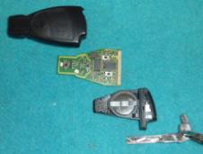
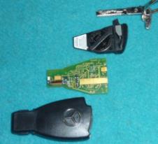
The Remote Control Key (A8/1) emits radio frequency (RF) (In Australia 315 MHz) frequency modulated (FM) signals to operate the remote control functions of unlocking, locking, and boot/trunk opening. The two internal batteries in the key fob are used to power these functions. If these batteries are weak or flat, the key will not unlock the doors or boot/trunk. A emergency mechanical key is stored inside the key fob and is provided in the event of this situation occurring.
The Remote Control Key also emits infra red (IR) signals to operate the convenience opening and closing feature. The IR signals are received by either IR sensor built into the two front door handles. The key needs to be pointing at the handle and within a few metres for the function to work. Better range is achieved if the receiving door handle is not in direct sunlight. The two internal batteries in the key fob are used to power the IR emitter for this function
How It Works - Remote Control Key and EIS
When a Remote Control Key (or a finger for that matter) is inserted in the electronic ignition switch (EIS or EZS) control unit (ignition lock) (N73), it operates a switch which activates an AC generator inside the ignition lock. This generator produces a high frequency (118KHz) sine wave which is inductively coupled to a small coil in the tip of the key fob.
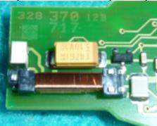
The AC voltage produced in the coil is rectified and the resulting DC voltage is used to power the Remote Control Key ignition functions. (The induced DC voltage was measured as 7.6V.) Using a separate inductive power supply very cleverly avoids reliance on the Remote Control Key batteries and ensures the Remote Control Key will operate the ignition even if it has internal flat or weak batteries.
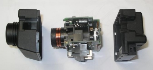
Once powered by the Induction Power Generator the Remote Control Key emits IR signals to, and receives IR signals from, the Drive Authorisation System (DAS) in the Electronic Ignition/Starter Switch (EIS) control module (N73). Start-up is enabled only after the transmitter key (A8/1) is identified by the encrypted data exchange between the
- EIS control unit (N73) and the
- ME-SFI control unit (N3/10) (with gasoline engine).
If the identification of the transmitter key (A8/1) is valid, the rotary lock of the EIS control unit (N73) is enabled. The transmitter key (A8/1) can now be turned. Once the correct code is recognised, the EIS allows the initial start procedures to commence, viz;
- rotary lock in EIS released, which allows the key to be turned in the lock to positions 1, 2 and 3, thus starting the car.
- steering wheel resumes it’s operating position (if this function has been previously activated),
- engine electric suction fan initiates,
- engine control module initiates,
- Automatic Climate Control (ACC) initiates,
- COMAND system initiates,
- gear selector lever lockout mechanism releases,
- any stored values for parameters such as seat and mirror positions, ACC settings, and COMAND settings etc. which are associated with this particular key are initiated (if this function has been previously activated).
When a non-recognised key is used the EIS Inductive Power Supply only operates for about 3 to 4 seconds after the key has been inserted into the Ignition Lock. When the key is not recognised, the Inductive Power Supply reverts to zero output for about 30 seconds when it generates another short burst of AC power in an attempt to read the key. I did not establish how many times it continues to do this before cancelling.
When a key is used that is recognised by the EIS, the Inductive Power Supply operates continuously until the key is removed.
Note the mechanical lock system in the EIS also prevents the Remote Control Key from being turned back to position 0 (Locked) and withdrawn from the EIS Ignition Lock unless the gear selector lever is in ‘P’ or Park.
Tip for Using Mechanical Key
Extract the Emergency Mechanical Key from the Remote Control Key Fob and after inserting into the door or boot lock, turn it all the way to the left (CCW).
Weak Batteries in Remote Control Key Fob
The Remote Control Key Fob functions may be affected by weak batteries in the key. If your key will not lock and unlock the car from 10m (30ft) or more, your batteries are weak and that will compromise the strength of the infrared (IR) beam. Try changing the batteries in the key before you go to more complicated (and expensive) efforts at restoring the function.
If the key will not turn in the ignition lock it is NOT caused by weak batteries in the key as the key electronics are powered inductively from the EIS Control Module when inserted into the ignition. See below for solutions to malfunctioning EIS.
Part Numbers - Remote Control Key Fob Batteries
- 2003 Update S500L Remote Key Fob has two batteries ie CR2025 x 2
- 2005 S500 Keyless Go Fob has only 1 Battery #2025
How To Change Batteries - Remote Control Key Fob
http://www.mbworld.org/forums/audio-...-pictures.html
Programming - Remote Control Key Fob
This video instruction is suitable for Car Key Master: CKM-100(PC Version) and CKM-200(Handhold Version), also it is suitable for Digimaster 3.
Electronic Ignition/Starter Switch (EIS or EZS) Control Module (N73)
Common Issue - Remote Control Key Will Not Rotate/Work/Turn in EIS (EZS)
Normally after inserting the correct Remote Control Key in the ignition lock (Electronic Ignition/Starter Switch (EIS) control module (N73)) it will turn instantly to position 1 (accessories), 2 (ignition on) and position 3 (engine start). However it seems that a common fault in the W220 occurs whereby the correct key will unlock the doors but once inserted in the ignition will not rotate and appears frozen. The vehicle cannot be started while the key will not turn.
Temporary Solution for Issue - Remote Control Key Will Not Rotate/Work/Turn in EIS (EZS)
The frozen key often happens intermittently causing huge frustration when out travelling. If you are lucky it may eventually start working again after continually trying and waiting twenty minutes. It is presumed that the EIS warms up slightly during this process.
Some owners have successfully used hair driers and electrical heaters to pre-warm the area around the ignition switch (EIS) to get the car started. Of course this is not a permanent fix but may get you out of immediate trouble.
Possible Failure Mechanism for Issue - Remote Control Key Will Not Rotate/Work/Turn in EIS (EZS)
It is now apparent, thanks to several BenzWorld Members and especially YouTube Poster John Kennedy, that one of the microprocessor chips on the EIS becomes sensitive to cold temperatures. Warming this particular chip temporarily solves the problem until it cools down sufficiently again. A DIY fix for this is available below.
Of course it may be that it is not the actual chip that is sensitive to cold but one or more of the solder joints connecting the chip to the board may have developed hair line cracks which open when cold and close when warmed.
Investigation of Issue - Remote Control Key Will Not Rotate/Work/Turn in EIS (EZS)
DIY Fix #1
The link shows one investigation with the bottom line that it was not a DIY solution. (Later note: YouTube Poster John Kennedy shows that a DIY fix is now possible.)
- Parts of a W220 Remote Control Key
- How the Remote Control Key Works in a W220
- Diagnosing An Intermittent Key
- Testing EIS Induction Power Generator Output
- Test of Induced Voltages In Actual OEM Remote Control Key
- Removing the EIS
http://www.benzworld.org/forums/w220-s-class/1300215-cold-weather-electronic-key-problems-5.html
DIY Testing EIS Induction Power Generator Output
In order to investigate the performance of the Induction Power Generator the author decided to measure the AC signal produced by the ignition lock (Electronic Ignition/Starter Switch (EIS) control module (N73)).
Construction of Dummy Test Key
Using parts from an old dismantled electrical transformer, I constructed a small coil on the end of an old small paint brush. I ground the end of the paint brush down to a cylinder of about 3mm diameter. I added a single piece of scrap transformer metal to the wooden cylinder to act as a core and bound both together with masking tape. This became the former for the coil and provided a nice winding surface. I wound approximately a thousand turns of 1.1mm diameter enamel insulated copper wire onto the former and soldered some insulated flexible wires for the test connections.

The exposed coil and connections were wrapped in masking tape and were inserted into an old empty key fob thus making a dummy test key.

Testing Using Dummy Test Key
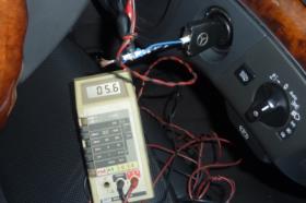
The AC voltage produced in the coil in my Dummy Test Key by the EIS Induction Power Generator was measured with a Digital Volt Meter (DVM) and a Cathode Ray Oscilloscope (CRO) in several M-B vehicles including my W220 S500L. The DVM readings proved to be unreliable, most likely due to the high frequency of the signals exceeding the DVM’s capability. The DVM readings were not analysed.
Note the actual voltages as measured with the Dummy Test Key are completely arbitrary and are dependent on the number of turns wound on the Dummy Test Key coil. They are useful for comparison purposes only.
DVM Reading Dummy Test Key AC Output in W220 S500L
CRO Reading Dummy Test Key AC Output in W220 S500L
CRO Scale: 1V/division with 10x Probe = 10V/division and 5µs/division
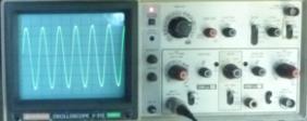
| W220 2003 Update S500L | |
|---|---|
| CRO AC Amplitude Peak to Peak | 63V p-p |
| Calculated CRO AC Amplitude | 22Vrms |
| CRO AC Timing Period | 8.5µs |
| Calculated CRO AC Frequency | 118KHz |
Comparison of Test Results for W204 C220, W211 E320, W209 CLK200K and W220 S500L
Note the actual voltages as measured are completely arbitrary and are dependent on the number of turns wound on the Dummy Test Key coil. They are useful for comparison purposes only.
The CRO Scale was: 1V/division with 10x Probe = 10V/division and 5µs/division.

| W204 2008 C220 CDI | W211 2004 E320 | W209 2005 CLK200K | W220 2003 Update S500L | |
|---|---|---|---|---|
| CRO AC Amplitude Peak to Peak | 85Vp-p | 85Vp-p | 87Vp-p | 63Vp-p |
| Calculated CRO AC Amplitude | 30Vrms | 30Vrms | 31Vrms | 22Vrms |
| CRO AC Timing Period | 8.5µs | 8.5µs | 8.5µs | 8.5µs |
| Calculated CRO AC Frequency | 118KHz | 118KHz | 118KHz | 118KHz |
| Normalised Comparison | 97% | 97% | 100% | 71% |
Test Conclusion
The Dummy Test Key induced coil voltages as measured by the CRO were very stable and consistent. The W220 Induction Power Generator output is only about 71% when compared to three other equal vintage Mercedes Benz vehicles.
It seems that the EIS Induction Power Generator output in the W220 was lower than the comparison vehicles. It was thought that this could be a high resistance in the fuses, fuse connections or cable connectors in the appropriate EIS supply lines or it could also be due to a faulty voltage regulator in the supply to the EIS Induction Power Generator circuit.
To try to determine exactly what determined the lower voltage the following tests were carried out.
Test of EIS Fuses
EIS Wiring Diagram
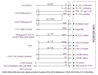
The voltage drop across f78/7.5A (FB Cockpit Left (RHD)) was measured with the key out, and key in.
| Battery Side of f78 | EIS Side of f78 | |
|---|---|---|
| Key Out | 12.69V | 12.69V |
| Key In and Not Operational | 12.60V | 12.58V |
| Key In and Operational | 12.54V | 12.52V |
The voltage drop across f78 seems reasonable. The voltage drops across X4/10 f2/60A and connectors Z4/3 and W36/2 were not measured.
Test of Induced Voltages In Actual OEM Remote Control Key
The tests conducted with the Dummy Test Key were useful to establish that the EIS was producing an AC frequency in the Induction Power Supply and that it was being inductively coupled into a Remote Control Key once inserted into the lock. The Dummy Test Key also provided useful comparison results between similar vintage Mercedes vehicles, albeit not exactly the same model.
These previous Dummy Test Key tests were ‘open circuit’ tests, ie the coil had no load connected to it and any induced voltage thus produced no current.
The next test aimed to measure the voltage induced in an actual Remote Control Key by the EIS once the key is inserted into the lock. This type of test is a ‘fully loaded’ test, ie the internal coil is connected to it’s normal circuits and thus any induced voltage will produce current and activate the circuits. It is a more meaningful test but more difficult to execute. It requires some very careful and fiddly soldering and should only be undertaken by someone with considerable electronic experience. Things to avoid are damage caused by electrostatic voltages, excess heat and rough or splattered soldering.
As explained previously the EIS generates a 118KHz sine wave which is inductively picked up in a small coil in the tip of the Remote Control Key fob. The coil is connected to the two tabs at the left edge of the coil in the next figure. The tab at the right end of the coil is not connected and is just for fastening that end of the coil.
The induction coil connections were traced as far as possible. Some tracks disappear under surface mount components, and the coil is connected to a diode and what I suspect is a zener diode resulting in a roughly regulated half wave DC power supply. The voltage produced cannot exceed the maximum voltage rating marked on the large electrolytic capacitor, the large yellow component shown just below the coil in the next figure.
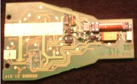
The capacitor has a value of 47μF 10V and is used to store the DC voltage produced. It’s time constant is many minutes, ie it holds the voltage charge and powers the key electronics long after the EIS has stopped generating the AC frequency.
Two wires were soldered across the coil (white (AC) and black (0V)) and also one wire (red (+V)) on to the (red band) end of the capacitor. The modified key could still be inserted into the key fob but without the battery holder and batteries. These were not needed anyway.
Measurement of DC Voltage Generated in S500L OEM Remote Control Key Electronics
Initial test was performed on a 2003 W220 S500L.


CRO Scale: 1V/division with 10x Probe = 10V/division and 5µs/division
These DC voltage tests were repeated on a 2008 W204 C220 CDI for comparison.
Comparison of W204 C220 (Left) and W220 S500L (Right) with CRO on Same Scale
CRO Scale: 1V/division with 10x Probe = 10V/division and 5µs/division

The amplitudes of both DC voltages were near enough the same at 7.60V and 7.50V respectively.
Replacing EIS Module
How To Remove - EIS Module
Turns out it was an easy job for a RHD car (probably much easier than a LHD car) to remove the EIS.
The first step was to remove the Glove Box so that the two nuts securing the Burred Walnut strip across the dash could be removed. Then the Walnut strip was removed making it easier to extract the Instrument Cluster.
For a RHD car the Instrument Cluster is removed using special tools or easy manufactured homemade ones fashioned out of 1mm thick sheet aluminium. See Instrument Cluster Repair Tool Kit here [1]
When inserted into the slots on each side of the Instrument Cluster they release plastic retaining clips. The left hand clip took much persuading but eventually released.
The EIS bezel is easily unscrewed using a special tool. See Electronic Ignition Switch (EIS) here [2]
Then it is an easy matter to reach inside and extract the EIS to the point where the connectors canbe removed. The mechanical rod which activates the Transmission Lock was also disconnected.

M-B Solution - Replacing EIS Module
The easiest but extremely expensive solution is to replace the EIS with a new one. It will cost over $3,000 and requires reprogramming of the new EIS to match the vehicle. As this is deemed a safety/security issue it can only be done by an authorized M-B agent.
DIY Solution No. 1 - Less Expensive Solution for Complete EIS Replacement
In Australia it is not necessarily a Dealer only option any more.
On line parts supplier Genuine Auto Parts will sell an EIS to the public for about AU$625 and Mercedes-Benz will supply a green (workshop) key with a AU$500 deposit, refunded on return of the key.
DIY Solution No. 2 - Replacing EIS Microprocessors
With a huge acknowledgement to YouTube Poster John Kennedy (and BenzWorld Member pinkster, Dean, for discovering the video) whose excellent diagnosis shown in the video referenced below positively demonstrates a faulty microprocessor which caused his issue.
In his case the fault was due to the lower Hc08 microprocessor chip (4j74y), shown in the next figure.
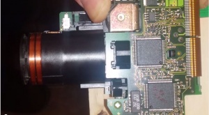
This microchip was very sensitive to cold temperature, shown here being cooled with a can of freezer solution. Once cooled the key freezes in the lock and will not turn.
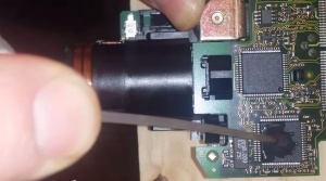
Warming the culprit chip, just with applied finger warmth for a few seconds, solves the issue and the key will turn again.
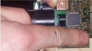
John Kennedy reports that the issue was fixed by replacing the faulty microprocessor.
Warning
Be aware that in other cases it may not be the microprocessor chip shown in this article that fails but could be other components or even the solder joints themselves so some diagnosis as per the video will be necessary to thoroughly isolate the faulty component or item.
Also be aware that working with electronic components requires some specialized skills such as fine soldering technique and appropriate earthing techniques to aid in prevention of electrostatic discharge. Surface mount electronic components can be very sensitive to excess heat and static electricity.
Replacement microprocessor chips are available but will require the original programme to be copied to the replacement chip which requires some speciallised equipment and knowledge.
Any comments on how the reprogramming is done would be appreciated, especially by some one who has successfully completed the DIY fix of an EIS.
Part Numbers - EIS Microprocessors
The part numbers for the microprocessors in the EIS from a 2003 (Update) W220 S500L are:
- The 64-pin quad flat pack (QFP) microprocessor at the bottom location in the figures above has the following information on its face.
- 00198128A3
- EWM
- Motorola Logo
- SC510108CFU
- 4J74Y
- QQCF0305
- 06/03 R2
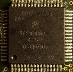
- The 64-pin quad flat pack (QFP) microprocessor at the top location in the figures above has the following information on its face.
- 001981287A
- Motorola Logo
- SC510108CFU
- 4J74Y
- QQCV0309
- 20/03 R1
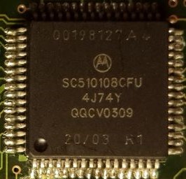
Parts Availability - EIS Microprocessors
With thanks to BenzWorld Member pinkster, Dean these microprocessors are available for about US$30 posted from this source. [3]
DIY Solution No. 3 - Replacement EIS via eBay
Australian BenzWorld Member iSteve reported that he purchased a replacement EIS with the same part number as his on eBay from the USA.
He was advised by his Indie that the US uses the same key frequency as Australia and hence the USA sourced EIS would be compatible with the Australian standards.
Initially the Indie only "cloned" one EPROM which resulted in some errors such as;
- A side marker lights error as Australian delivered cars do not have side marker lights.
- The Steering Wheel Comfort feature would not work.
- The odometer reading of the new unit was incorrect and unfortunately was higher than the original.
iSteve reported that his Indie used an In Circuit Serial Programming (ICSP) cloning tool and a laptop which allowed programming a microprocessor chip while it is still attached to the application circuit. That is there is no need for chip swapping.
The ICSP tool was used to save the original Hex files and copy them over to the replacement EPROMs. There were 88 differences between the old and the replacement unit.
After a second attempt whereby both "EPROMs were cloned" the new unit is working the same as the original but with no cold start problem.
Reference [4]
DIY Solution No. 4 - "The Ultimate EIS Repair Guide"
MHH Auto senior member 'bawarek' has posted an excellent although very technical article titled, "The ultimate Mercedes EIS repair guide".
See http://mhhauto.com/Thread-The-ultimate-Mercedes-EIS-repair-guide
Internal Components - EIS Module
Here are some of the internal components of the IES and their functions.
- Motorola SC510108CFUis a 64pin microprocessor. (There are two of these in my EIS.) (I could not find a pin configuration diagram identifying pin functions.)
- PCA82C250 is a 8 pin Philips Can Controller Interface. It provides differential transmit and receive to the CAN-C (Engine) bus.
- TJA1054 is a 14 pin Philips Fault-tolerant CAN Transceiver. . It provides differential transmit and receive to the CAN-B (Interior) bus.
- 42760V5 is a 5 pin 5V Regulator in a TO252-5 case.
- IR322A is a hexfet power mosfet in a TO252-AA case.
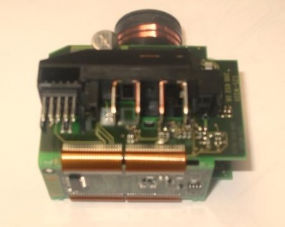
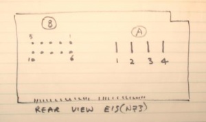
Connector Pin Diagram - EIS Module
Here are the pin diagrams for the connectors.
Matching rear view showing fixed connectors.
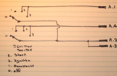
Circuit Diagram for ‘A’ Connector for EIS.
Also shown for interest is the circuit diagram for the EIS Lock Solenoid. A signal from one of the microprocessors turns on the hex mosfet which activates the solenoid and allows the key to rotate in the EIS.
