Tail lights: Difference between revisions
| (4 intermediate revisions by 2 users not shown) | |||
| Line 19: | Line 19: | ||
| | | | ||
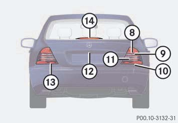
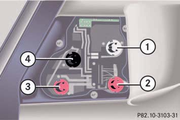
* 1. Turn signal lamp (white socket) | * 1. Turn signal lamp (white socket) | ||
* 2. Tail, parking ,standing | * 2. Tail, parking, standing and side marker lamp (red socket) | ||
* 3. Tail lamp, rear fog lamp (red socket) | * 3. Tail lamp, rear fog lamp (red socket) | ||
* 4. Backup lamp (black socket) | * 4. Backup lamp (black socket) | ||
| Line 127: | Line 127: | ||
== Washer == | == Washer == | ||
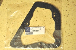
[[File:W220_A2208260091_taillight_washer.jpg|thumb|none|A2208260091 fits for both sides.]] | [[File:W220_A2208260091_taillight_washer.jpg|thumb|none|A2208260091 fits for both sides.]] | ||
== TURN SIGNAL, L CHECK LAMP! == | |||
The following video shows how to permanently repair and eliminate this warning. | |||
'''Step by step Video''' | |||
{| | |||
|{{#ev:youtube|https://youtu.be/snaa4tnnVCc|320|center|W220 TURN SIGNAL, CHECK LAMP (By Masood)|frame}} | |||
|} | |||
== Oxidized contacts of rear turn signal indicators== | |||
A common issue with the rear turn signal indicators is oxidized contacts on the bulb socket. | |||
{| | |||
|[[File:W220 Rear Left Tail Light and Fog Light Bulb Holder.JPG|thumb|none|Rear left tail and fog light with bulb]] | |||
|[[File:W220 Rear Tail Light and Fog Light Bulb Holder Showing Contact Marks.JPG|thumb|none|Oxidized contact marks on the socket.]] | |||
|} | |||
Obviously if the turn signal indicators are showing signs of oxidation then so are all the other bulb holders and their sockets. | |||
* Remove the boot lining as required. | |||
* Remove the rear light assembly. [10mm socket] | |||
* Note the position of the coloured bulb holders. | |||
** Black - reverse light | |||
** White - turn indicator | |||
** Pink - fog and tail lights | |||
* Remove just '''one bulb holder''' from its socket. Even though the bulb holders are all uniquely coded it is easier to modify them one at a time. | |||
* Note the position of the contact marks on the bulb holder socket. The contact marked with a black felt tip pen is the earth or zero volts contact. | |||
* Clean the contact points on the bulb holder socket with solvent. | |||
* Lightly scuff the contact points on the bulb holder socket with sand paper. | |||
* Using a soldering iron tin the contact points on the bulb holder socket. | |||
{| | |||
|[[File:W220 Tinning the Rear Tail Light and Fog Light Bulb Holder Socket.JPG|300px]] | |||
|[[File:W220 Example of Tinned Bulb Holder Socket.JPG|300px]] | |||
|} | |||
* Repeat for the other contact points on this socket. | |||
* Now move your attention to the mating bulb holder. | |||
* Inspect this bulb holder socket's contact points and note the oxidation. | |||
* Remove the globe. | |||
* Remove just one contact by depressing the tab with a small screw driver. | |||
* Clean the contact areas on the bulb holder contact with solvent. | |||
* Lightly scuff the contact areas on the bulb holder contact with sand paper. | |||
* Using a soldering iron tin the contact areas on the bulb holder contact. | |||
{| | |||
|[[File:W220 Example of Oxidized Contacts on a Bulb Holder.JPG|200px]] | |||
|[[File:W220 Contact Removed from a Bulb Holder.JPG|300px]] | |||
|[[File:W220 Example of Tinning Contact on a Bulb Holder.JPG|300px]] | |||
|} | |||
* Reinsert the bulb holder contact into the bulb holder '''BEFORE''' doing the next one. | |||
* Repeat for all other contacts. | |||
* Reinstall the bulb holder in its socket, '''BEFORE moving on to the next one'''. | |||
* Repeat for all other bulb holders and sockets. | |||
* Check the resistances of each light and its circuit by using a DVM to measure the resistances from the cable connection. Clip one side of the DVM to the earth lead marked with a black felt tip pen in the photo above. | |||
** Reverse light (black bulb holder) 0.6 Ohms. | |||
** Turn indicator (white bulb holder) 0.6 Ohms. | |||
** Tail light (one filament in pink bulb holder) 0.6 Ohms. | |||
** Fog light (one filament in pink bulb holder) 5 Ohms. | |||
* Reinstall the rear tail light assembly and repeat for the other side. | |||
== Resources == | == Resources == | ||
http://www.benzworld.org/forums/w220-s-class/2085186-rear-fog-lamp-license-plate-left.html#post9518458 | http://www.benzworld.org/forums/w220-s-class/2085186-rear-fog-lamp-license-plate-left.html#post9518458 | ||
Latest revision as of 00:48, 15 July 2021
Back to: WIS 82.10 Exterior Lights
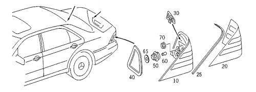
Location – Tail Lights
|
|
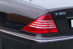
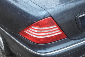
Facelift (after 30/09/2002)
- A2208200764 - tail lamp left
- A2208200864 - tail lamp right
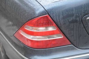
Pre-facelift (before 01/09/2002)
The only difference in pre-facelift and facelift taillights are lens which in facelift version has four transparent horizontal lines instead of pre-facelift's two.
- A2208200164 - tail lamp left
- A2208200264 - tail lamp right
Aftermarket
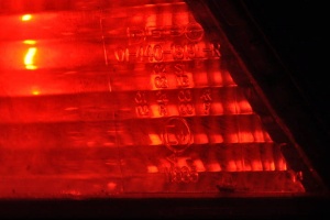
DEPO
|
 |
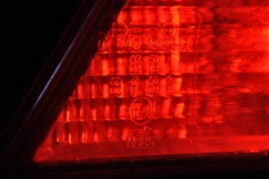 |
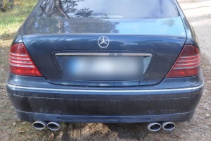
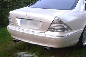
Note: DEPO taillight should not be mixed with the original facelift taillights, since DEPO taillight is a bit lighter (see below).
DEPO All Smoke
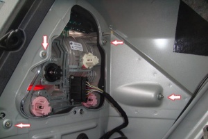
Removing
- Open your trunk and take the cover out.
- There are four screws, remove them (see below).
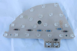
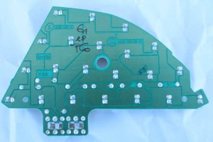
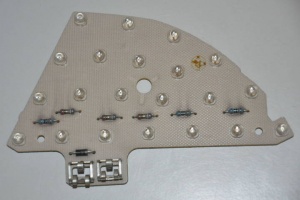
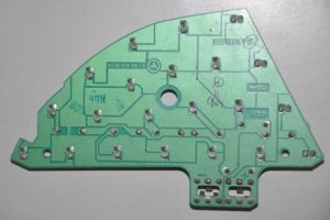
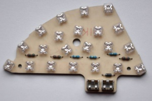
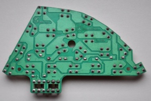
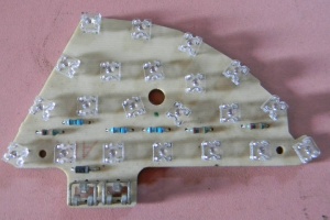
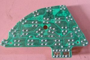
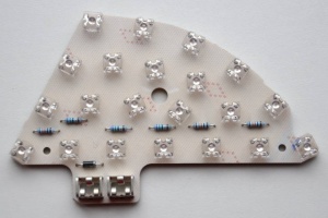
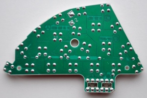
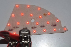
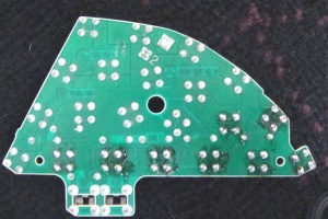
LED board
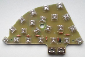
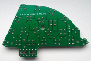
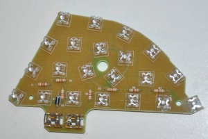
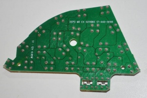
For the break light W220 taillights use LED board.
- A2208200411 - right
- A2208200311 - left
There seem to be several versions of LED boards. V?/V2.2 which has square LED bulbs and V2.5/V2.6 which has round LED bulbs.
 |
 |
 |
 |
 |
 |
 |
 |
 |
 |
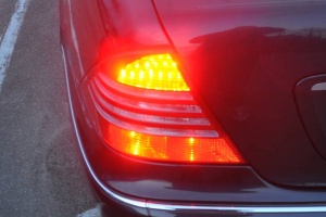
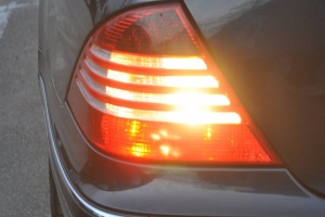
Defective LED board
Even a single failed LED bulb in the LED board can cause the board to be disabled by the vehicle. If this happens, the error message will appear on the instrument cluster and for the duty of brake lamp will be delegated to fog lamp.
 |
 |
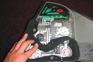
Replacing LED bulbs
The whole LED board unit is expensive. LED bulbs can be replaced by soldering.
- Remove the taillight from vehicle.
- Take the circuit board out, it is attached by one screw (see below).
- Use a 12v adapter by connecting it to the circuit board and see which bulbs are damaged.
- Remove damaged bulbs and install new ones using a soldering iron. Make sure the new led lights are positioned the same exact way the old ones were, otherwise they will not work.
- Once this is done, you can insert the circuit board back into the car. Make sure prior to this all the lights are working.
You can buy square LED bulbs by using this keyword "LED 7.62MM 638NM ALINGAP RED CLR - LTL912SEKSA".
Washer
TURN SIGNAL, L CHECK LAMP!
The following video shows how to permanently repair and eliminate this warning.
Step by step Video
Oxidized contacts of rear turn signal indicators
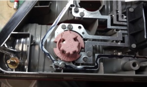
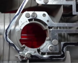
A common issue with the rear turn signal indicators is oxidized contacts on the bulb socket.
 |
 |
Obviously if the turn signal indicators are showing signs of oxidation then so are all the other bulb holders and their sockets.
- Remove the boot lining as required.
- Remove the rear light assembly. [10mm socket]
- Note the position of the coloured bulb holders.
- Black - reverse light
- White - turn indicator
- Pink - fog and tail lights
- Remove just one bulb holder from its socket. Even though the bulb holders are all uniquely coded it is easier to modify them one at a time.
- Note the position of the contact marks on the bulb holder socket. The contact marked with a black felt tip pen is the earth or zero volts contact.
- Clean the contact points on the bulb holder socket with solvent.
- Lightly scuff the contact points on the bulb holder socket with sand paper.
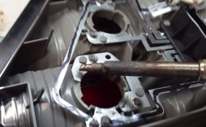
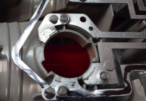
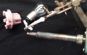
- Using a soldering iron tin the contact points on the bulb holder socket.
|
|
- Repeat for the other contact points on this socket.
- Now move your attention to the mating bulb holder.
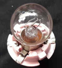
- Inspect this bulb holder socket's contact points and note the oxidation.
- Remove the globe.
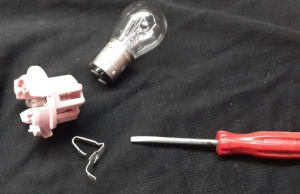
- Remove just one contact by depressing the tab with a small screw driver.
- Clean the contact areas on the bulb holder contact with solvent.
- Lightly scuff the contact areas on the bulb holder contact with sand paper.
- Using a soldering iron tin the contact areas on the bulb holder contact.
|
|
|
- Reinsert the bulb holder contact into the bulb holder BEFORE doing the next one.
- Repeat for all other contacts.
- Reinstall the bulb holder in its socket, BEFORE moving on to the next one.
- Repeat for all other bulb holders and sockets.
- Check the resistances of each light and its circuit by using a DVM to measure the resistances from the cable connection. Clip one side of the DVM to the earth lead marked with a black felt tip pen in the photo above.
- Reverse light (black bulb holder) 0.6 Ohms.
- Turn indicator (white bulb holder) 0.6 Ohms.
- Tail light (one filament in pink bulb holder) 0.6 Ohms.
- Fog light (one filament in pink bulb holder) 5 Ohms.
- Reinstall the rear tail light assembly and repeat for the other side.
