Windshield wiper: Difference between revisions
(updated with parts) |
Ricebubbles (talk | contribs) |
||
| (21 intermediate revisions by one other user not shown) | |||
| Line 1: | Line 1: | ||
== Parts == | == Parts == | ||
[[File:W220_EPC_windshield_wiper.png|thumb|none|Windshield wiper related parts in [[EPC]].]] | |||
=== Windshield Wiper Blade === | === Windshield Wiper Blade === | ||
| Line 43: | Line 43: | ||
|} | |} | ||
Aftermarket replacement | Aftermarket replacement (for LHD vehicles): | ||
* OEM BOSCH Aerotwin A946S 3397118946 680mm (EUR 30) | |||
* OEM BOSCH Aerotwin 3397118946 (EUR 30) | |||
* VALEO 574317 700mm (EUR 35) | * VALEO 574317 700mm (EUR 35) | ||
* VALEO 577869 680mm (EUR 25) | * VALEO 577869 680mm (EUR 25) | ||
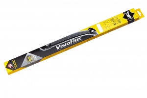
* SWF VisioFlex 119438 650mm (EUR 30) | * SWF VisioFlex 119438 650mm (EUR 30) | ||
* SWF VisioFlex 119389 700mm (EUR 40) | |||
* CHAMPION KF68/C02 680mm (EUR 50) | |||
* DENSO DF123 700mm (EUR 30) | |||
{| | |||
|[[File:W220_BOSCH_aerotwin_A946S_3397118946.jpg|thumb|none|BOSCH Aerotwin A946S]] | |||
|[[File:W220_SWF_visioflex_119438.jpg|thumb|none|SWF VisioFlex 119438.]] | |||
|[[File:W220_Champion_KF68C02.jpg|thumb|none|CHAMPION KF68/C02.]] | |||
|} | |||
[[File:W220_SWF_visioflex_119389.jpg|thumb|none|SWF VisioFlex 119389.]] | |||
<!-- http://www.benzworld.org/forums/w220-s-class/1635251-s-cl-class-wiper-blades.html --> | <!-- http://www.benzworld.org/forums/w220-s-class/1635251-s-cl-class-wiper-blades.html --> | ||
====Rubber only==== | |||
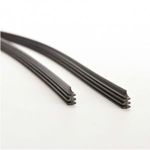
It is possible, and much cheaper (~EUR 8 for a pair) to replace only the wiper blade rubber, but make sure that the new blades have the correct form. | |||
Length: 685mm (27”) | |||
Width: 6mm | |||
{| | |||
|[[File:W220_BOSCH_aerotwin_A946S_3397118946_refill.jpg|thumb|none|BOSCH Aerotwin refill (rubber).]] | |||
|[[File:W220_windshield_wiper_rubber_bosch_vs_alca.jpg|thumb|none|BOSCH Aerotwin refill vs ALCA refill.]] | |||
|} | |||
{| | |||
|{{#ev:youtube|https://www.youtube.com/watch?v=0yWx7c5zkB8|320|center|Rubber replacement on a Bosch Aerotwin® wiper blade.|frame}} | |||
|{{#ev:youtube|https://www.youtube.com/watch?v=Jtlr_oTENMU|320|center|Rubber replacement on a Bosch flat wiper blade.|frame}} | |||
|} | |||
[http://swissint.com/shop/ SWISSINT sells] high-quality Aerotwin wiper blade rubber refill with graphite coating (Art. Nr AT750). | |||
These are made of regular rubber but are simply coated with graphite, | |||
a coal-like, semi-metallic element used in pencil lead. | |||
When rubber is impregnated with powdered graphite, the blade is able to glide across | |||
the glass more smoothly and quietly due to reduced friction. | |||
Graphite also helps to protect the rubber from damage and deterioration. | |||
BOSCH Aerotwin original rubber is also graphite coated. | |||
== Windshield | == Windshield wiper park position == | ||
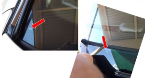
There are two marks on the front windscreen which identify the parked positions of the windscreen wiper blades. | There are two marks on the front windscreen which identify the parked positions of the windscreen wiper blades. | ||
The marks are a tiny window in the black undercoating, about a 1.5mm x 10mm clear slit in the black coating. | |||
One mark is on the right side and one in the centre of the windscreen. | |||
There is no mark on the left side. The two marks can be used to reinstall the wiper mechanisms if they have been removed. | |||
Note it is obvious that the same windscreen is used for LHD and RHD vehicles, | |||
hence the marks are only really useful for LHD cars. | |||
For RHD cars the position of the right mark can be measured and transferred to the left side as a guide. | |||
[[File:W220 Windscreen Wiper Park Position Markings.JPG|thumb|none|Right side and center mark (RHD vehicle).]] | |||
If after a full wiping cycle the wiper blades do not park in the park position, the position has to be corrected by reinstalling wiper arms (see instructions below). | |||
{| class="wikitable" | |||
! Error Code | |||
! Generated By | |||
! Description | |||
|- | |||
|B1017 | |||
|SAM-FL - Front left signal acquisition and actuation module | |||
|Component M6/1 (wiper motor) is not within the park position (terminal 31B). | |||
|} | |||
== Remove/install windshield wiper blades == | |||
{| | |||
|{{#ev:youtube|https://www.youtube.com/watch?v=YeOQNK2FzVs|320|center|W220 windshield wiper blade removal.|frame}} | |||
|} | |||
==Wiper system== | |||
<!-- GF82.30-P-0003S, Wiper system (WS), function, 2.7.98 | |||
Models 215, 220 --> | |||
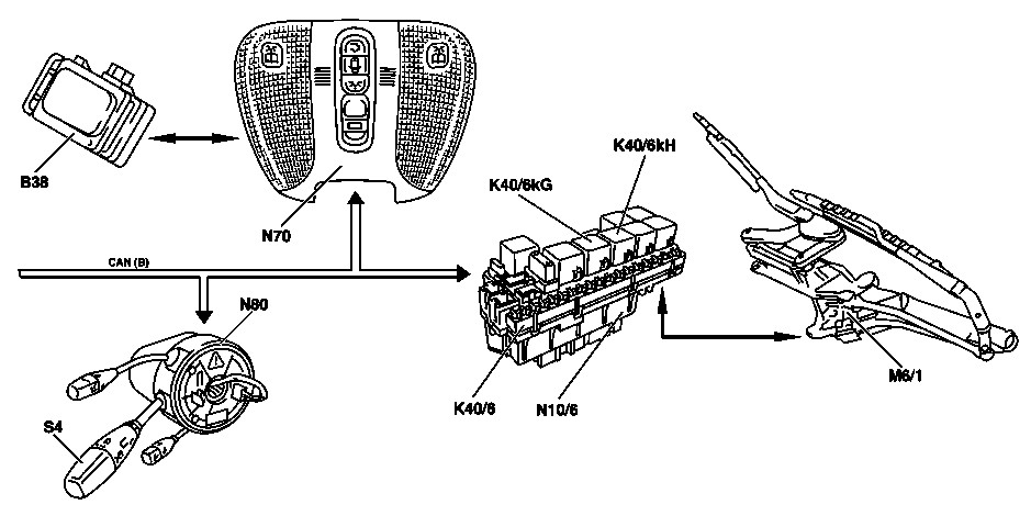
Networking of components: | |||
{| | |||
|[[File:W220_wiper_system.png]] | |||
| | |||
* CAN-B - CAN interior | |||
* B38 - Rain sensor (valid up to 08/31/2002) | |||
* B38/2 - Rain/light sensor (valid as of 9/1/02) | |||
* M6/1 - Wiper motor | |||
* N10/6 - Left front SAM control unit | |||
* N70 - Overhead control panel control unit | |||
* N80 - Steering column module | |||
* S4 - Combination switch | |||
|} | |||
Preconditions for function: | |||
* Circuit 15R ON | |||
The windshield wiper system is operated using the combination switch (S4). | |||
The following functions are possible: | |||
* Touch wiping: A single wipe is performed. (To do this, push the combination switch (S4) to the detent) | |||
* Intermittent wiper valid up to 31/08/2002: with automatic intermittent wipe control via the rain sensor (B38). To do this, turn the combination switch (S4) to position 1. | |||
* Intermittent wiper valid as of 02/09/2002: with automatic intermittent wipe control via the rain/light sensor (B38/2). To do this, turn the combination switch (S4) to position 1. | |||
'''Switch positions''' | |||
At combination switch (S4) position: interval (rain sensor position) | |||
the wiper requests are sent by the rain sensor | |||
(B38) or as of 01/09/2002 by the rain/light sensor (B38/2) via the | |||
overhead control panel control unit (N70). | |||
If another wiper position is selected using the combination switch | |||
(S4), the request is transmitted directly to the wiper by the left SAM | |||
control module (N10/6). | |||
* Intermittent wiping with slow speed (stage 1, approx. 40 cycles/min.) To do this, turn the combination switch (S4) to position 2. | |||
* Wiping at high speed (stage 2, approx. 60 cycles/min). To do this, turn the combination switch (S4) to position 3. | |||
* Washing: The windshield is wiped with additional water. To do this, push the combination switch (S4) beyond detent. | |||
A data transfer between the left SAM control unit (N10/6) and the | |||
overhead control panel control unit (N70) only takes place if the data | |||
has changed or one of the two control units has been initialized. | |||
Operation is interrupted when "circuit 15R OFF". | |||
The combination switch (S4) information and the requests from | |||
the overhead control panel control unit (N70) are provided by | |||
the interior CAN. | |||
A two-stage standard wiper control is used. It is actuated | |||
directly by the left SAM control unit (N10/6). | |||
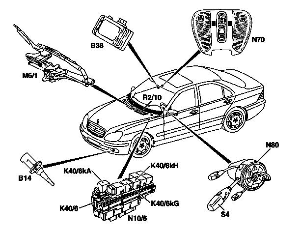
=== Wiper system, location of components (up to 31/05/2000) === | |||
<!-- GF82.30-P-0003-01S, Wiper system (WS), location of components | |||
MODEL 215, 220 up to 31.5.00 --> | |||
{| | |||
|[[File:W220_wiper_system_up_to_31-05-2000.png]] | |||
| | |||
* B14 - Ambient temperature display temperature sensor | |||
* B38 - Rain sensor (up to 31/08/2002) | |||
* K40/6 - Left front fuse and relay module | |||
* K40/6kA - Wiper park position heater relay (for left hand drive vehicles only) | |||
* K40/6kG - Wiper stage 1 and 2 relay | |||
* K40/6kH - Wiper On and Off relay | |||
* M6/1 - Wiper motor | |||
* N10/6 - Left front SAM control module | |||
* N70 - Overhead control panel control module | |||
* N80 - Steering column module | |||
* R2/10 - Wiper park position heater (for left hand drive vehicles only) | |||
* S4 - Combination switch | |||
|} | |||
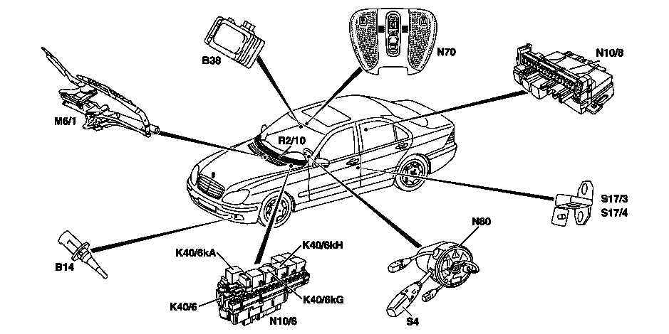
=== Wiper system, location of components (as of 01/06/2000) === | |||
<!-- GF82.30-P-0003-01SN Wiper system (WS), location of components | |||
MODEL 215, 220 as of 1.6.00 --> | |||
{| | |||
|[[File:W220_wiper_system_as_of_01-06-2000.png]] | |||
| | |||
* B14 - Ambient temperature display temperature sensor | |||
* B38 - Rain sensor (up to 31/08/2002) | |||
* B38/2 - Rain/light sensor (as of 01/09/2002) | |||
* K40/6 - Left front fuse and relay module | |||
* K40/6kA - Wiper park position heater relay (for left hand drive vehicles only) | |||
* K40/6kG - Wiper stage 1 and 2 relay | |||
* K40/6kH - Wiper On and Off relay | |||
* M6/1 - Wiper motor | |||
* N10/6 - Left front SAM control module | |||
* N10/8 - Rear SAM control module | |||
* N70 - Overhead control panel control module | |||
* N80 - Steering column module | |||
* R2/10 - Wiper park position heater (for left hand drive vehicles only) | |||
* S4 - Combination switch | |||
* S17/3 - Left front door contact switch | |||
* S17/4 - Right front door contact switch | |||
|} | |||
===Wiper function=== | |||
<!-- GF82.30-P-3004S, Wiper, function, 2.3.98 | |||
Models 215, 220 | |||
--> | |||
Slow wiping (stage 1) function sequence: | |||
* The slow windshield wiping function is switched on by turning the combination switch (S4) to position 2 | |||
* The position of the combination switch (S4) is read in by the steering column module (N80) and sent to the interior compartment CAN as a message | |||
* The left front SAM control module (N10/6) receives this message and controls the wiper On and Off relay (K40/6kH) | |||
* Circuit 15R is switched via the wiper stage 1 and 2 relay (K40/6kG) to "circuit 53" (slow wiping) by the wiper motor (M6/1) . (The wiper stage 1 and 2 relay (K40/6kG) is then not actuated.) | |||
* The wiper motor operates at slow speed | |||
Fast wiping (stage 2) function sequence: | |||
* The fast windshield wiping function is switched on by turning the combination switch (S4) to position 3 | |||
* The position of the combination switch (S4) is read in by the steering column module (N80) and sent to the interior compartment CAN as a message | |||
* The left front SAM control module (N10/6) receives this message and actuates the wiper On and Off relay (K40/6kH) and the wiper stage 1 and 2 relay (K40/6kG) | |||
* Circuit 15R is switched via the wiper stage 1 and 2 relay (K40/6kG) to "circuit 53b" (fast wiping) by the wiper motor(M6/1). (The wiper stage 1 and 2 relay (K40/6kG) is then actuated.) | |||
* The wiper motor runs at high speed | |||
Switching off wiping function: | |||
* If the combination switch (S4) has been turned to position 0, the above-mentioned message is no longer on the interior compartment CAN | |||
* If the wiper motor now reaches the park position, the left front SAM control module (N10/6) ensures that the wiper stops (If switch-off was accomplished from stage 2, the wiper motor is switched back to the slow stage until it reaches the park position) | |||
* The wiper motor stops in the park position | |||
The wiper motor (M6/1) can be switched back to intermittent wiping by the automatic speed reduction. | |||
As of 01/09/2002 the functions anti-lock protection, lock detection, stopping and final wiping are monitored independently by the reversing wiper system (UWA). | |||
===Windshield intermittent wiping function=== | |||
<!-- GF82.30-P-3003S, Windshield intermittent wiping, function, 2.3.98 | |||
Models 215, 220 | |||
--> | |||
Operational sequence: | |||
* The intermittent wiping function is switched on by turning the combination switch (S4) to position 1. | |||
* The position of the combination switch (S4) is read in by the steering column module (N80) and sent to the interior compartment CAN as a message | |||
* The left front SAM control module (N10/6) receives this message and initiates one wipe cycle (if the wiper was already moving, this wipe cycle is first brought to an end) | |||
* After one wipe cycle, the wiper motor (M6/1) is stopped | |||
* The intermittent pause is started. | |||
* At the end of the pause, the next wipe cycle is executed. | |||
'''Control of wiper motor''' | |||
The left front SAM control module (N10/6) controls the wiper motor | |||
(M6/1) by means of the wiper stage 1 and 2 relay (K40/6kG) and | |||
wiper On and Off relay (K40/6kH) so that the wiper wipes at speed | |||
stage 1. | |||
'''Interruption of intermittent pause''' | |||
If another wiper function is requested during an intermittent pause, | |||
this function is executed without taking the intermittent pause into | |||
consideration. After completion of this function, the intermittent | |||
pause is started again. | |||
'''Control of the intermittent pause''' | |||
The intermittent pause is dependent on the amount of moisture | |||
present on the windshield. The left front SAM control module (N10/6) | |||
analyses for this purpose the data from the rain/light sensor (B38/2). | |||
The exchange of data between the left front SAM control module | |||
(N10/6) and the rain/light sensor (B38/2) takes place via the interior | |||
compartment CAN and, because the rain/light sensor (B38/2) is not | |||
connected directly to the interior compartment CAN, via the | |||
overhead control panel control module (N70) as an interface. | |||
In the event of a failure of the rain/light sensor (B38/2) the | |||
intermittent time is set to approx. 5 s. | |||
As of 01/06/2000 there is a safety cutout when the front door is open. | |||
'''System functions''' | |||
Function prerequisites: | |||
* Circuit 15R ON | |||
'''Windshield wipers''' | |||
Switch position I = intermittent = pause duration dependent on quantity of moisture; can be regulated upward to continuous wiping stage 2. | |||
Switch position II = stage 1 = continuous wiping 40 cycles/min | |||
Switch position III = stage 2 = continuous wiping 60 cycles/min | |||
A two-stage standard wiper control is used. This is actuated directly | |||
from the left SAM control module (N10/6). | |||
Data are only transferred between the left SAM control module | |||
(N10/6) and the overhead control panel control module (N70) | |||
when there is a change to the data, or when one of the two | |||
control modules is initialized. The functions are interrupted with | |||
"Circuit 15R OFF". | |||
'''Intermittent wipe (valid as of 01/09/2002)''' | |||
Continuous wiper control by the rain/light sensor (B38/2). | |||
The top priority for switching on the wiper is always assigned to the | |||
combination switch (S4). Information such as the vehicle speed, the | |||
position of the wiper switch, the ambient light conditions as well as | |||
the outside temperature are received by the overhead control panel | |||
control module (N70) and processed in the algorithm implemented. | |||
The wiper system is actuated via the interior compartment CAN by | |||
means of the left SAM control module (N10/6). | |||
The wiper is controlled depending on the particular quantity and frequency of moisture by: | |||
* Individual wipe cycles | |||
* Continuous wipe | |||
* Continuous wiping with the selection of the required wiper speed | |||
The intermittent time is determined by the rain/light sensor (B38/2) | |||
(up to stage 2 continuous wiping). If communication with the | |||
overhead control panel control module (N70) fails at switch position I | |||
the intermittent wiping function is activated. If intermittent wiping is | |||
transmitted from position 0, the wipe cycle takes place immediately. | |||
After interrupting intermittent wiping by a wiper function, the | |||
intermittent pause elapses. | |||
Intermittent times (emergency mode): | |||
* 1st intermittent time T/1 = 5 s 1 s | |||
* 2nd intermittent time T/2 = 1.5 s (T/1 with automatic speed reduction) | |||
The rain/light sensor (B38/2) is activated by switching on the | |||
intermittent wiper setting and thus the CAN message generated by | |||
the left SAM control module (N10/6) via the overhead control panel | |||
control module (N70). The left SAM control module (N10/6) receives | |||
the request for intermittent wiping via the interior compartment CAN. | |||
'''Switch positions (valid as of 01/09/2002)''' | |||
With the combination switch (S4) position: intermittent | |||
(rain sensor position) the requests for the wiper take place via the | |||
overhead control panel control module (N70) from the rain/light | |||
sensor (B38/2). | |||
If using the combination switch (S4) another wiper setting is | |||
selected, the request comes directly from the left SAM control | |||
module (N10/6) to the wiper. | |||
The combination switch (S4) information as well as the | |||
requests from the overhead control panel control module (N70) | |||
are supplied by means of the interior compartment CAN. | |||
==== Service Information ==== | |||
<!-- SI82.30-P-0003A, Service Information: Intermittent wipe function, 26.10.05 | |||
MODEL 211, 209 | |||
MODEL 220, 215 with CODE (803) Model year 2003 | |||
MODEL 203 with CODE (804) Model year 2004 --> | |||
Intermittent wiping does not function when vehicle is standing still in the rain: | |||
If the combination switch is set to I (intermittent wipe) and the driver | |||
or front passenger door is opened, wiping is stopped for safety reasons. | |||
Persons exiting or entering the vehicle are thus protected from splash water. | |||
The windshield wiper will, for example, not come on automatically if | |||
the windshield is being cleaned by hand while the ignition is on or the | |||
engine is running. | |||
Intermittent wiping is reactivated: | |||
* when the selector lever is moved to D or N (for manual transmissions: when clutch is applied). | |||
* when the combination switch is moved to setting II or III. | |||
Side effect: If the driver gets out to, for example, close the garage | |||
door, automatic wiping will be deactivated until a gear is engaged | |||
again. | |||
On the vehicle, check whether the customer complaint is a result of the built-in system logic. | |||
Explain to the customer how the intermittent wipe function is design to work. | |||
===Safety switch-off function (as of 01/06/2000)=== | |||
<!-- GF82.30-P-3005SN, Safety switch-off (WS), function, 9.3.00 | |||
MODELS 215, 220 as of 1.6.00 --> | |||
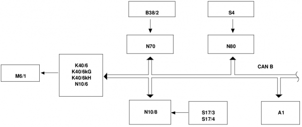
Networking of safety cutout Intermittent wipe: | |||
{| | |||
|[[File:W220_networking_of_safety_cutout_intermittent_wipe.png|600px]] | |||
| | |||
* CANB - Interior CAN | |||
* A1 - Instrument cluster | |||
* B38/2 - Rain/light sensor (as of 01/09/2002) | |||
* K40/6 - Left front fuse and relay module | |||
* K40/6kG - Wiper stage 1 and 2 relay | |||
* K40/6kH - Wiper On and Off relay | |||
* M6/1 - Wiper motor | |||
* N10/6 - Left front SAM control module | |||
* N10/8 - Rear SAM control module | |||
* N70 - Overhead control panel control module | |||
* N80 - Steering column module | |||
* S4 - Combination switch | |||
* S17/3 - Left front door contact switch | |||
* S17/4 - Right front door contact switch | |||
|} | |||
'''Safety cutout with the intermittent wiping function''' | |||
The following safety precaution has been incorporated in order to | |||
minimize the risks of possible injuries: | |||
* The intermittent wiping function (combination switch in position 1) is suppressed at a vehicle speed of less than 5 km/h as | |||
soon as one of the front doors is opened. | |||
* The function is possible again as soon as both front doors are closed | |||
In order to permit the intermittent wiping function | |||
even in the event of a defective door contact switch (S17/3, S17/4), | |||
the states of the door contact switches have no effect at speeds above 3 km/h. | |||
'''Fault analysis:''' | |||
* Failure of the serial communication interface to the left SAM control module (N10/6) - wiper motor | |||
In the event of a failure of the serial communication interface or a | |||
fault report from the wiper motors (e.g.: Hall sensors defective), even | |||
when there is as yet no wiper request, an error message is sent from | |||
the left SAM control module (N10/6) via the interior compartment | |||
CAN to the instrument cluster (A1). | |||
The rain sensor and light information are sent from the overhead | |||
control panel control module (N70) only in the event of changes. | |||
'''Wiper startup suppression''' | |||
Suppression of the wiper function with the driver or passenger | |||
door open to prevent accidents. | |||
The wiper function is suppressed when: | |||
* Combination switch (S4) is in position 1 (intermittent stage) | |||
* Driver or passenger door is open | |||
* v < 5 km/h and | |||
* Shift lever position is in P or N | |||
If the driver or passenger door is open at v > 3 km/h, there is no | |||
wiper startup suppression. | |||
Actuation of the wiper after a suppressed actuation takes place if: | |||
* the wiper switch has been pressed | |||
* an engaged drive position is detected, or a gear is engaged | |||
* v > 3 km/h | |||
A wipe cycle which has already commenced, is not | |||
interrupted. The wiper moves as far as the park position. | |||
'''Networking''' | |||
For the safety cutout, the signals of the front door contact switch are | |||
needed. These are read in by the rear SAM control module (N10/8) | |||
and are sent via the interior compartment CAN to the left front SAM | |||
control module (N10/1). | |||
The vehicle speed signal comes from the instrument cluster (A1) via | |||
the interior compartment CAN to the left front SAM control module (N10/1). | |||
'''Fault report of the wiper''' | |||
If, due to the internal thermal protection, the wiper signals the overload bit, | |||
this is signaled by the left SAM control module (N10/6) to the instrument cluster as a wiper fault. | |||
'''Failure or lack of CAN communication to the overhead control panel''' | |||
In the event of an incorrect message, the wiper request is rejected | |||
and only responded to again with the next correct message. In the | |||
event of five incorrect messages, the intermittent wipe control takes | |||
place as under 1 (T = 5 s +/- 1 s). If correct communication with the | |||
rain/light sensor (B38/2) can be established again, then the system | |||
switches back to rain/light sensor mode. | |||
No fault is displayed in the instrument cluster. | |||
'''Timeout of the wiper startup suppression''' | |||
* For door contacts (rear SAM): doors closed (default value) | |||
* For combination switch (S4) request (electronic ignition switch/steering column module): last valid value | |||
* For v-signal: v > 3km/h | |||
The function can be coded out. | |||
'''Anti-lock protection, lock detection, stopping, final wiping''' | |||
The functions are carried out independently by the UWA (reversal wiper system). | |||
'''Special case for wiper startup suppression''' | |||
A wipe cycle that has already been initiated (with request via | |||
combination switch (S4) "position 1" or "final wiping") is not | |||
interrupted by opening the driver or passenger doors. The wiper | |||
movement takes place until it reaches the park position. Further | |||
wiper requests (with combination switch (S4) "position 1") are, | |||
however, suppressed with the above-described criteria. | |||
=== Wiper system automatic speed reduction function === | |||
<!-- GF82.30-P-4006S, Wiper system automatic speed reduction, function, 9.3.98 | |||
Models 215, 220 --> | |||
The automatic speed reduction has an effect on the functions (valid as of 01/09/2002): | |||
* Wiping in stage "1" | |||
* Wiping in stage "2" | |||
If the vehicle speed drops below 5 km/h, | |||
then the left front SAM control module (N10/6) switches the | |||
wiper motor (M6/1) from these functions back to intermittent wiping. | |||
The intermittent pause is controlled in this case by the rain/light | |||
sensor (B38/2). | |||
'''Switching back to the selected wiper stage (valid until 31/08/2002)''' | |||
If with increasing vehicle speed the value of | |||
8 km/h is exceeded, the left front SAM control module (N10/6) | |||
switches the wiper motor (M6/1) automatically back again to the | |||
wiper stage ("1" or "2") set at the combination switch (S4). | |||
The vehicle speed signal required for the speed reduction is | |||
received at the left front SAM control module (N10/6) via the | |||
interior compartment CAN from the instrument cluster (A1). | |||
The speed reduction can be reset manually by pressing the | |||
combination switch (S4) again for each desired function. | |||
'''Switching back to the selected wiper stage (valid as of 01/09/2002)''' | |||
If a rain/light sensor (B38/2) is provided, the system always switches | |||
back to rain sensor mode. For this purpose, the rain/light sensor | |||
(B38/2) must be activated and "circuit 15 ON". If the rain/light sensor | |||
(B38/2) is present but defective, the standard way of switching back | |||
(switching back one stage) is carried out. | |||
Instantaneous status: v-back-switching not in USA. | |||
=== Anti-lock protection for wiper motor function === | |||
<!-- GF82.30-P-4008S, Anti-lock protection for wiper motor, function, 2.3.98 | |||
Models 215, 220 --> | |||
'''Lock-up recognition''' | |||
Lockup of the wiper motor (M6/1) is detected by the left front SAM | |||
control module (N10/6) by the lack of signals from the cam switch. | |||
'''Anti-lock protection for wiping in "stage 2" function''' | |||
If this signal from the cam switch is missing for more than 4 s, then | |||
the left front SAM control module (N10/6) switches the wiper motor | |||
(M6/1) to "stage 1". | |||
If the signal is still missing for a further 8 s, then the left front SAM | |||
control module (N10/6) switches the wiper motor (M6/1) off. | |||
'''Anti-lock protection for the functions one-touch wiping, | |||
intermittent wiping, washing and wiping in "stage 1"''' | |||
With these functions the left front SAM control module | |||
(N10/6) switches the wiper motor (M6/1) off, if the signals from the | |||
cam switch do not appear for more than 12 seconds. | |||
In all cases, the anti-lock protection is canceled if: the | |||
corresponding function is requested again by pressing the | |||
combination switch (S4) or "circuit 15R" is switched on again. | |||
If the wiper motor (M6/1) still locks after canceling the anti-lock | |||
protection, the wiper motor (M6/1) is switched off again as described above. | |||
=== Slowing down wiper motor function === | |||
<!-- GF82.30-P-4007S, Slowing down wiper motor, function, 2.3.98 | |||
Models 215, 220 --> | |||
Following the completion of a wiping operation, the wipers must | |||
come to a stop in the park position. | |||
'''Stopping wiper motor''' | |||
To stop the motor, the wiper On and Off relay (K40/6kH ) is switched | |||
off by the left front SAM control module (N10/6). | |||
Through the opening of this relay: | |||
* The connection circuit 53 for the wiper motor (M6/1) is disconnected from the voltage supply circuit 15R | |||
* The connection circuit 53 for the wiper motor (M6/1) is connected to ground via an electronic switch (FET) of the SAM; this short-circuits the motor | |||
* This short circuit decelerates the motor (eddy current dynamometer) | |||
'''Prerequisites for stopping wiper motor''' | |||
The stopping of the wiper motor (M6/1) is only initiated if: | |||
* The wiper motor is switched off (combination switch (S4) in position 0) or | |||
* Intermittent wiping is switched on (combination switch (S4) in position 1) and an intermittent pause has just started | |||
* The cam switch is closed, and thus the park position has been reached | |||
In order to detect the park position, the wiper motor (M6/1) has a cam switch. | |||
When the motor runs through the park position, the cam switch is actuated. | |||
The signal from the cam switch is interrogated continuously by | |||
the left front SAM control module (N10/6) . | |||
=== Wiper motor === | |||
<!-- GF82.30-P-4104S, Wiper motor, location / task / design / function, 9.3.98 | |||
Models 215, 220 --> | |||
{| | |||
|[[File:W220_wiper_motor_location.jpg]] | |||
| | |||
* M6/1 - Wiper motor | |||
|} | |||
The wiper motor is located in the water trough underneath the windshield. | |||
The purpose of the wiper motor is to drive the windshield wipers with two speed stages and detect exact end position of the wipers. | |||
The drive for the windshield wipers consists of an electric motor with three brushes, gear and the cam switch on the output shaft. | |||
<!-- GF82.30-P-4104-01S, Wiper motor, function --> | |||
'''Function''' | |||
The wiper motor (M6/1) is a DC motor with three brushes. | |||
Depending on which pair of brushes is energized, the wiper motor | |||
(M6/1) operates at different speeds. | |||
'''Cam switch''' | |||
The cam switch is closed when the wiper motor (M6/1) is in the rest position. | |||
With each wiping cycle the cam switch opens and closes when the non-actuated state is reached. | |||
This generates the signal c. 31b. | |||
Using the circuit 31b signal, it is possible to determine whether the wiper motor (M6/1) | |||
* is operating correctly, | |||
* locked up, | |||
* or in the rest position. | |||
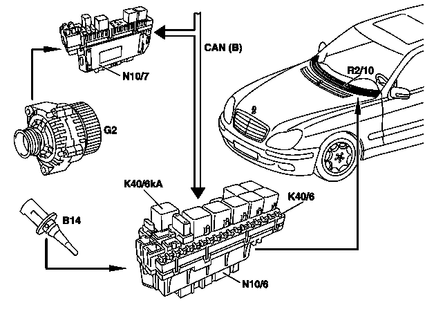
===Wiper rest heater function=== | |||
<!-- GF82.30-P-2003S, Wiper rest heater, function, 2.3.98 | |||
MODEL 215.### 1#, 220 --> | |||
Interlinkage of components: | |||
{| | |||
|[[File:W220_wiper_rest_heater.png]] | |||
| | |||
* B14 - Outside temperature sensor | |||
* G2 - Generator | |||
* K40/6 - Left front fuse and relay module | |||
* K40/6kA - Wiper rest heater relay (only with left-hand steering) | |||
* N10/6 - Left front SAM control module | |||
* N10/7 - Right front SAM control module | |||
* R2/10 - Wiper rest heater | |||
|} | |||
Prerequisites for operation of wiper rest heater: | |||
* Engine: ON | |||
'''Function''' | |||
At outdoor temperatures below 5 °C the [[windshield]] is heated directly | |||
in the area where the wiper blades rest by the wiper rest heater (R2/10). | |||
If the outdoor temperature increases to above 7°C the wiper rest | |||
heater is switched off. | |||
'''Actuation of wiper rest heater (R2/10)''' | |||
When switch-on conditions are fulfilled the left front SAM control | |||
module (N10/6) actuates the wiper rest heater relay (K40/6kA) on the | |||
left front fuse and relay module (K40/6). The wiper rest | |||
heater relay (K40/6kA) then switches on circuit 30 to the wiper rest | |||
heater (R2/10). | |||
Required data: | |||
* Outdoor temperature: The outdoor temperature sensor (B14) is read in directly by the left front SAM control module (N10/6) to check the outdoor temperature. | |||
* Status of circuit 61 (generator): The status of c.61 is read in by the right front SAM control module (N10/7) and relayed to the left front SAM control module (N10/6) via the CAN bus (passenger compartment). | |||
== Windshield washer function == | |||
<!-- GF82.35-P-3002S, Windshield washer, function, 10.3.98 | |||
MODEL 215, 220 --> | |||
The windshield is wiped while water is sprayed. | |||
Function sequence | |||
* Press combination switch (S4) beyond catch point | |||
* The signal from the combination switch (S4) is read in by the jacket tube module (N80) and the corresponding message is transferred to the CAN bus (passenger compartment), | |||
* The left front SAM control module (N10/6) and right front SAM control module (N10/7) receive this message. | |||
* The left front SAM control module (N10/6) starts the wiper motor (M6/1), the right front SAM control module (N10/7) actuates the windshield washer fluid pump (M5/1): | |||
** The windshield washer fluid pump (M5/1) runs as long as the combination switch (S4) is actuated. | |||
* When the combination switch (S4) is released, the wiper motor (M6/1) continues to run to wipe off the remaining water. The number of wiping cycles depends on the time the combination switch (S4) was activated: | |||
** If actuated less than 1 second the wiper wipes one more time, | |||
** If actuated longer, 3 wiping cycles are completed. | |||
* After completion of the wiping operation the wiper motor (M6/1) is decelerated. | |||
The wiper motor (M6/1) runs in stage 1 for washing. | |||
Wiping is accomplished at speed 2 only when the wipers were simultaneously set to speed 2. | |||
'''Control of washer pump''' | |||
The windshield washer fluid pump (M5/1) is actuated directly by the | |||
right front SAM control module (N10/7). During the washing | |||
operation the windshield washer fluid pump (M5/1) is connected to | |||
ground by an electronic switch (transistor) in the control module. | |||
In the event of an overload the pump is switched off by the right | |||
front SAM control module (N10/7). | |||
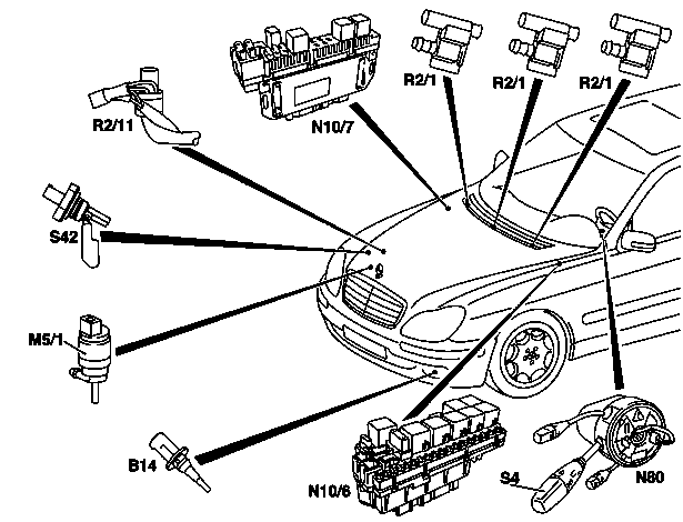
=== Windshield washer, location of components === | |||
<!-- GF82.35-P-0001-01S, Windshield washer, location of components --> | |||
{| | |||
|[[File:W220_windshield_washer_components.png]] | |||
| | |||
* B14 - Ambient temperature display temperature sensor | |||
* M5/1 - Windshield washer fluid pump | |||
* M6/1 - Wiper motor | |||
* N10/6 - Left front SAM control module | |||
* N10/7 - Right front SAM control module | |||
* N80 - Jacket tube module | |||
* R2/1 - Heated windshield washer nozzle | |||
* R2/11 - Washer nozzle hose heater | |||
* S4 - Combination switch | |||
* S42 - Windshield washer fluid level switch | |||
|} | |||
=== Windshield washer pump === | |||
<!-- GF82.35-P-4101-02S, Washer pump position --> | |||
{| | |||
|[[File:W220_washer_pump_position.jpg]] | |||
| | |||
* M5/1 - Windshield washer fluid pump | |||
* M5/2 - Headlamp washer fluid pump | |||
* S42 - Windshield washer fluid level switch | |||
|} | |||
<!-- GF82.35-P-4101S, Washer pump, location/purpose/design/function, 9.3.98 | |||
MODEL 215, 220 --> | |||
The purpose of the pump is to pump windshield washer fluid for washing the windshield. | |||
The windshield washer fluid pump (M5/1) is driven by a DC motor integrated into the pump housing. | |||
<!-- GF82.35-P-4101-01S, Washer pump, function --> | |||
'''Function''' | |||
For operation of the windshield washer the windshield washer | |||
fluid pump (M5/1) pumps the windshield washer fluid from the | |||
windshield washer reservoir through the hoses and windshield | |||
washer nozzles to the windshield. | |||
For this purpose ground is connected to the motor for the | |||
windshield washer fluid pump (M5/1) by the right front SAM | |||
control module (N10/7). | |||
This actuation is accomplished directly by an electronic switch | |||
(transistor) in the control module and not by a relay. | |||
===Coolant/washer fluid level voltage coding=== | |||
<!-- GF54.30-P-4001S, Coolant/washer fluid level voltage coding, function, 1.7.98 | |||
Models 215, 220 --> | |||
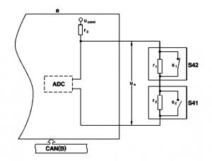
[[File:W220_coolant_washer_fluid_level_coding.png|300px]] | |||
The circuit shown in the figure is used to | |||
determine the level of the coolant and | |||
windshield washer fluid. | |||
The coolant level indicator switch (S41) and | |||
the windshield washer fluid level indicator | |||
switch (S42) are connected in series. Both | |||
switches are read in via two lines by the right | |||
front SAM control unit (N10/7). | |||
The figure illustrates the status of the | |||
switches when the coolant and washer fluid | |||
are at the correct levels. | |||
'''Voltage coding:''' | |||
For voltage coding the resistors r<sub>1</sub> and r<sub>2</sub> are connected in parallel | |||
with the switches s<sub>1</sub> and s<sub>2</sub>. | |||
(The values from r<sub>1</sub> and r<sub>2</sub> must be different.) | |||
When the switches are open, these resistors, together with r<sub>3</sub> | |||
of the right front SAM control unit (N10/7), form a voltage divider | |||
which is supplied with the constant voltage U<sub>const</sub>. | |||
The voltage U<sub>e</sub> at the input of the right front SAM control unit (N10/7) | |||
therefore depends on the positions of the switches and the values of the resistors. | |||
With the two switches, there are therefore four possible switch combinations (see table). | |||
Each of these combinations results in a different value for voltage U<sub>e</sub> | |||
at the input of the right front SAM control unit (N10/7). | |||
'''Evaluation''' | |||
The voltage U<sub>e</sub> is applied at the input of the ADC (analog-to-digital | |||
converter) of the right front SAM control unit (N10/7). The ADC | |||
(analog-to-digital converter) converts the analog voltage into a digital value. | |||
This is necessary since the processor of the right front SAM control | |||
unit (N10/7) can only work with digital values. | |||
The processor compares the values to the threshold values stored in | |||
memory and if necessary, passes an appropriate message (coolant | |||
and/or washer fluid level too low) on the CAN (passenger compartment). | |||
The instrument cluster (A1) reads this message and controls the | |||
multifunction display (A1p13) accordingly. | |||
If the resistance values and the voltage U<sub>const</sub> are known, U<sub>e</sub> | |||
can be calculated using the following formula: | |||
U<sub>e</sub> = U<sub>const</sub> * (r<sub>1</sub> + r<sub>2</sub> )/(r<sub>1</sub> + r<sub>2</sub> + r<sub>3</sub>) | |||
'''Assignment of switch status/warning messages:''' | |||
The following table shows the warning messages which appear | |||
according to the status of the switches. | |||
These messages can be acknowledged by pressing the reset button | |||
on the instrument cluster (A1). | |||
{| class="wikitable" | |||
! Status Coolant !! Status Washer fluid !! Warning on the multifunction display | |||
|- | |||
| open || closed || No message | |||
|- | |||
| open || open || "CHECK WASHER FLUIDLEVEL" | |||
|- | |||
| closed || closed || "CHECK COOLANT LEVEL" | |||
|- | |||
| closed || open || "CHECK COOLANT LEVEL" (The message "CHECK WASHER FLUID LEVEL" has a lower priority.) | |||
|} | |||
If there is an open circuit in the wiring or if a sensor fails, no | |||
message appears on the multifunction display (A1p13). A fault is | |||
stored, however, in the fault memory of the right front SAM control | |||
unit (N10/7). | |||
=== Windshield washer nozzle and windshield washer nozzle hose heater function === | |||
<!-- GF82.35-P-3003S, Windshield washer nozzle and windshield washer nozzle hose heater, function, 11.3.98 | |||
MODEL 215, 220 --> | |||
The heated windshield washer nozzle (R2/1) and washer nozzle | |||
hose heater (R2/11) are switched on automatically when: | |||
* C. 61 ON (engine: ON) and | |||
* outdoor temperature less than 5°C is recognized. | |||
Switch-off is accomplished: | |||
* C.61 OUT (engine: OFF) or | |||
* outdoor temperature greater than 7°C are recognized. | |||
If the values (outdoor temperature, c.61) are not present or not | |||
logical the heater elements are not switched on! | |||
'''Control of heater elements''' | |||
The heater elements for the heated windshield washer nozzle (R2/1) | |||
and washer nozzle hose heater (R2/11) are connected in parallel. | |||
Control of the heated windshield washer nozzles (R2/1) and washer | |||
nozzle hose heater (R2/11) is accomplished directly from the right | |||
front SAM control module (N10/7). For this purpose the SAM | |||
completes circuit 30 to the heater elements. | |||
Required data: | |||
* The ambient temperature is recorded by the ambient temperature display temperature sensor (B14). The left front SAM control module (N10/6) reads in the sensor and sends the measured value as a message on the CAN (interior). | |||
* The status of c.61 (generator G2) is read in directly by the right front SAM control module (N10/7). | |||
== Remove and install wiper arm == | |||
<!-- AR82.30-P-6100M, Remove and install wiper arm, 26.11.09 | |||
MODEL 220, 215 --> | |||
{| | |||
|[[File:W220_remove_install_wiper_arm.jpg]] | |||
| | |||
* 1 - Wiper arm | |||
* 2 - Nuts | |||
* 3 - Retainer | |||
|} | |||
# Move wiper system to parked position | |||
# Open engine hood and move to vertical position | |||
# Unscrew nuts (2) | |||
# Remove wiper arm (1). Installation: The wiper blade must rest directly on the mark (arrow) in the silk screen print of the windshield. On model 215, 220 as of the use of aero wipers, the retainer (3) is to be removed with the use of new wiper blades. | |||
# Install in the reverse order | |||
# Check operation of windshield wipers | |||
Torque specifications: | |||
* Nut on wiper arm: 33 Nm | |||
==Remove/install wiper system== | |||
<!-- AR82.30-P-6400M, Remove/install wiper system, 26.11.09 | |||
MODEL 220, 215 --> | |||
{| | |||
|[[File:W220_remove_install_wiper_system.jpg]] | |||
| | |||
* 1 - Expanding rivet | |||
* 2 - Water repellent piece | |||
|} | |||
{| | |||
|[[File:W220_remove_and_install_wiper_system.jpg]] | |||
| | |||
* 3 - Nut | |||
* 4 - Wiper system | |||
* 5 - Knurled nut | |||
* M6/1x1 - Wiper motor connector | |||
|} | |||
Removing: | |||
# Remove wiper arms | |||
# Remove 4 expansion rivets (1) | |||
# Remove water repellent (2) upward out of fold (arrow) | |||
# Unscrew 4 nuts (3). Do not twist knurled nut (5), otherwise the incline angle of the wiper system is changed. | |||
# Disconnect connector (M6/1x1) at wiper motor | |||
# Remove wiper system (4) | |||
Installing: | |||
# Insert wiper system (4) | |||
# Screw in 4 nuts (3) | |||
# Move wiper motor to parked position | |||
# Install water repellent (2) | |||
# Install wiper arms | |||
# Check operation of windshield wipers | |||
Torque specifications: | |||
* Nut, wiper system: 20 Nm | |||
==Remove/install wiper motor== | |||
<!-- AR82.30-P-6800M, Remove/install wiper motor, 26.11.09 | |||
MODEL 220, 215 --> | |||
{| | |||
|[[File:W220_remote_install_wiper_motor.jpg]] | |||
| | |||
* 1 - Nut, wiper motor shaft | |||
* 2 - Crank | |||
* 3 - Screw/bolt, wiper motor | |||
* 4 - Bracket | |||
* A - Angle between crank and rib | |||
* M6/1 - Wiper motor | |||
|} | |||
Remove: | |||
# Open engine hood and move to vertical position | |||
# Remove wiper system | |||
# Unscrew nut of wiper motor shaft (1) | |||
# Pull off crank (2) with wiper linkage | |||
# Unclip connector at bracket (4) | |||
# Remove screws/bolts at wiper motor (3) | |||
# Remove wiper motor (M6/1) | |||
Install: | |||
# Move wiper motor (M6/1) to parked position | |||
# Insert wiper motor (M6/1) | |||
# Screw in wiper motor (3) screws/bolts | |||
# Unclip connector at bracket (4) | |||
# Align crank (2) in angle (A) to top rib of wiper motor bracket | |||
# Turn nut on wiper motor shaft (1) | |||
# Install wiper system | |||
# Close engine hood | |||
# Check operation of windshield wipers | |||
Torque specifications: | |||
* Bolt on wiper motor mount: 9 Nm | |||
* Nut on wiper motor shaft: 19 Nm | |||
Test and adjustment values for windshield wiper: | |||
* Dim Angle "A" between crank and rib: 74° | |||
==Move wiper motor to parking position== | |||
<!-- AR82.30-P-6800-01E, Move wiper motor to parking position | |||
MODEL 163, 202, 208, 210, 215, 220, 230 /475, 461, 463 --> | |||
{| | |||
| | |||
[[File:W220_move_wiper_motor_to_parking_position_1.png|thumb|none|Illustrated on model 163]] | |||
| | |||
[[File:W220_move_wiper_motor_to_parking_position_2.png|thumb|none|Shown on models 215, 220, 230]] | |||
| | |||
[[File:W220_move_wiper_motor_to_parking_position_3.png|thumb|none|Using Model 463 as an example]] | |||
|} | |||
# Connect wiper motor (M6/1) to wiper motor connector (1) | |||
# Hold wiper motor (M6/1) using the left hand. | |||
# Switch on ignition. | |||
# Set combination switch to "stage 1". | |||
# Turn combination switch back to "level 0". | |||
# If the wiper motor (M6/1) is in the park position, switch off the ignition. | |||
# Detach wiper motor connector (1) from wiper motor (M6/1). | |||
==Wiper arm adjustment== | |||
<!-- AH82.30-P-0001-01A, Notes on wiper arm adjustment | |||
Model 164, 166, 171.4, 172.4, 190, 197, 203, 204, 205, 207, 209, 211, 212, | |||
213, 215, 217, 218, 220, 222, 230, 231, 238, 240, 251, 253, 292 --> | |||
By checking the angle of incidence of the wiper arms in parked position | |||
and reversing position, it can be assessed whether one wiper arm, | |||
both wiper arms or the wiper system are to be adjusted. | |||
The wiper arms are adjusted in case the check values deviate from the | |||
tolerance range in reversing position or in case the check values | |||
deviate from the tolerance range in reversing position and parked | |||
position. | |||
The angle of incidence is changed by twisting (crossing over) the | |||
wiper arms with the aid of the adjustment lever. The angle of incidence | |||
of the wiper arm always has to be adjusted in parked position. | |||
In doing so the angle of incidence in parked position and reversing | |||
position changes by the same amount. The angle of incidence of the | |||
wiper arm to be adjusted is changed by at least the value of the | |||
tolerance deviation in reversing position. To make sure that both | |||
adjustment values lie within the tolerance range, the angle of incidence | |||
has to be checked again in parked position and corrected if necessary. | |||
The windshield wiper system is adjusted in case check values of | |||
both wiper arms deviate from the tolerance range in parked position. | |||
===Check wiper arms and adjust=== | |||
<!-- AR82.30-P-6000T, Check wiper arms and adjust, 15.03.2016 | |||
Model 211, 215, 220, 230, 240 --> | |||
Shown on MODEL 211, windshield wiper system in reversing position: | |||
{| | |||
|[[File:W220_check_wiper_arms_and_adjust.jpg]] | |||
| | |||
* 1 - Driver-side wiper arm | |||
* 2 - Passenger-side wiper arm | |||
* A - Distance between driver-side wiper blade and A-pillar | |||
* B - Distance between front passenger side wiper blade and A-pillar | |||
|} | |||
Caution: | |||
* When working on raised wiper arm, ensure that this does not fall onto the windshield. Otherwise windshield will be damaged. | |||
* When moving the windshield wiper system out of the park position or changing from reversing position to parked position, ensure that the wiper arm makes no direct contact with the windshield. Otherwise, the windshield may be scratched. | |||
Check: | |||
# Manually position windshield wiper system in reversing position | |||
# Remove wiper blade from driver-side wiper arm (1). The driver-side wiper arm (1) must not be moved. | |||
# Check driver-side wiper arm (1). The reversing position for the driver-side wiper arm (1) corresponds to the distance from the driver-side wiper blade to the A-pillar (A). Distance between driver-side wiper blade and A-pillar (A) approx. 50 mm. | |||
# Remove wiper blade from passenger-side wiper arm (2). The passenger-side wiper arm (2) must not be moved. | |||
# Check passenger-side wiper arm (2). Model 211: The reversing position of the passenger-side wiper arm (2) corresponds to the distance from the passenger-side wiper blade to the A-pillar (B) of approx. 350 mm. | |||
Clean: | |||
# Clean wiper blade fixtures on driver-side wiper arm (1) and passenger-side wiper arm (2) using a clean cloth | |||
# Cover driver-side wiper arm (1) using suitable aids (scratch protection) | |||
# Measure angle of incidence of wiper arm (1) to windshield, note this down and compare test value with adjustment value. | |||
# Cover passenger-side wiper arm (2) using suitable aids (scratch protection) | |||
# Measure angle of incidence of wiper arm (2) to windshield, note this down and compare test value with adjustment value. | |||
Adjust: | |||
# Adjust angle of incidence of driver-side wiper arm (1) in park position. If the test values deviate from the tolerance range in the reversing position or in the parked and reversing position. The driver-side wiper arm (1) must be adjusted by at least the value of the tolerance deviation in the reverse position. | |||
# Adjust windshield wiper system. In the event that the check values of the wiper arm (1) deviate from the tolerance range in park position. | |||
# Cover driver-side wiper arm (1) using suitable aids and move windshield wiper system out of park position. | |||
# Install driver-side wiper blades. | |||
# Adjust angle of incidence of passenger-side wiper arm (2) in park position. If the test values deviate from the tolerance range in the reversing position or in the parked and reversing position. The passenger-side wiper arm (2) must be adjusted by at least the value of the tolerance deviation in the reverse position. | |||
# Adjust windshield wiper system. In the event that the check values of the wiper arm (2) deviate from the tolerance range in park position. | |||
# Cover the passenger-side wiper arm (2) using suitable aids and move the windshield wiper system out of park position. | |||
# Install wiper blades. | |||
Test and adjustment values of wiper arms: | |||
* Angle of incidence of wiper arm on driver-side in reversing position: | |||
** Left-hand drive vehicle: –1,0°...–6,0° | |||
** Right-hand drive vehicle: +1,0°...+6,0° | |||
* Angle of incidence of wiper arm on passenger-side in reversing position: | |||
** Left-hand drive vehicle: –0,5°...–4,0° | |||
** Right-hand drive vehicle: +0,5°...+4,0° | |||
* Angle of incidence of wiper arm on driver-side in parked position: | |||
** Left-hand drive vehicle: +2,0°...+6,0° | |||
** Right-hand drive vehicle: –2,0°...–6,0° | |||
* Angle of incidence of wiper arm on passenger-side in parked position | |||
** Left-hand drive vehicle: +2,0°...+6,0° | |||
** Right-hand drive vehicle: –2,0°...–6,0° | |||
Torque specifications: | |||
* Nut, wiper system: 20 Nm | |||
===Check wiper arms=== | |||
<!-- AR82.30-P-6000-01T, Check wiper arms | |||
Model 211, 215, 220, 230, 240 --> | |||
{| | |||
|[[File:W211589022100_adjusting_tool_set.jpg|thumb|none|W211589022100 (Adjusting tool set).]] | |||
|[[File:W220_check_wiper_arms_1.jpg|thumb|none|]] | |||
|[[File:W220_check_wiper_arms_2.jpg|thumb|none|Shown on driver-side wiper arm (1).]] | |||
|[[File:W220_check_wiper_arms_3.jpg|thumb|none|Shown on driver-side wiper arm (1).]] | |||
|} | |||
# Remove angle gauge (A) from the adjustment tool set. | |||
# Insert adapter (B) into the guide (arrow) of the angle gauge (A) and fasten with the screw/bolt to angle gauge (A). | |||
# Position wiper arm (1) to be adjusted in reversing position. | |||
# Slide adapter (B) together with angle gauge (A) onto wiper blade mount of wiper arm (1) to be adjusted and attach with screw/bolt. | |||
# Lower wiper arm (1) to be adjusted carefully onto windshield. All three contact points at the foot of the angle gauge (A) must make contact with the windshield. | |||
# Read off the angle of incidence of the driver-side wiper arm (1) in reversing position on the scale of the angle gauge (A), note down and compare to the corresponding specified value. | |||
# Raise wiper arm (1) to be adjusted and remove adapter (B) together with angle gauge (A). | |||
# Raise wiper arms (1), cover with appropriate aids (scratch protection) and set down on windshield. | |||
# Move wiper arms (1) to park position and remove aid (scratch protection) from wiper arms (1). | |||
# Repeat test procedures 3 to 6 at the wiper arm (1) to be adjusted in parked position. | |||
===Adjust wiper arms=== | |||
<!-- AR82.30-P-6100-01T, Adjust wiper arms | |||
Model 140, 170, 171, 172, 203 up to 5/31/03, 211, 215, 220, 230, 240 --> | |||
Adjustment of the wiper arm angle of incidence is always done in | |||
the parked position. If the check values deviate from the tolerance | |||
range adjustment occurs both in reversing position and parked | |||
position. In doing so, the driver-side wiper arm or front passenger-side | |||
wiper arm is adjusted by at least the value of the tolerance deviation in | |||
reversing position. | |||
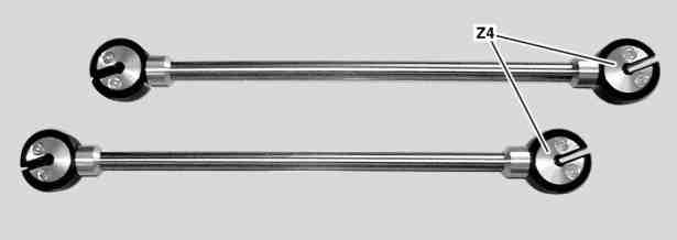
Use adjustment levers (Z4) from adjustment tool set. | |||
[[File:W220_adjust_wiper_arms_1.jpg]] | |||
# Remove angle gauge (A) and adjustment lever (Z4) from adjustment tool set. | |||
# Insert adapter into guide of angle gauge (A) and fix in place with screw/bolt at angle gauge (A). | |||
# Slide adapter together with angle gauge (A) onto wiper blade mount of wiper arm to be adjusted and attach with screw/bolt. | |||
# Lower wiper arm to be adjusted carefully onto windshield. All three contact points at the foot of the angle gauge (A) must make contact with the windshield. | |||
# Place adjustment levers (Z4) as far from each other as possible on the wiper arm to be adjusted. The wiper arm is twisted with the aid of the adjustment lever (Z4) that was positioned close to the angle gauge (A). The second adjustment lever (Z4) is used as a counterholder. | |||
# Press adjustment lever (Z4) in required direction until the wiper arm to be adjusted is at least distorted by the value of the tolerance deviation in the reversing position. | |||
# Remove adjustment lever (Z4) from wiper arm to be adjusted. | |||
# Read off angle of incidence for adjusted wiper arm on scale of angle gauge (A), note it down and compare against the test and adjustment values, adjust again if necessary. | |||
# Detach angle gauge (A) with adapter from adjusted wiper arm. | |||
{| | |||
|[[File:W220_adjust_wiper_arms_2.jpg|thumb|none|Shown on model 203, driver side.]] | |||
|[[File:W220_adjust_wiper_arms_3.jpg|thumb|none|Shown on model 203, driver side.]] | |||
|} | |||
===Adjusting wiper system=== | |||
<!-- AR82.30-P-6400-01M Adjusting wiper system | |||
Model 215, 220 --> | |||
The wiper system may only be adjusted if the test values of both wiper | |||
arms deviate from the tolerance range in park position. | |||
# Install angle gauge (A) to driver-side wiper arm (1). | |||
# Open hood. | |||
# Remove spreader clip (2) and push back water collector (3) until jam nut (4) is accessible. | |||
# Loosen jam nut (4) and turn adjusting nut (5) until the correct adjustment value is shown on the dial of the angle gauge (A). | |||
# Tighten locknut (4). | |||
# Install spreader clip (2). Replace damaged expansion clip (2). | |||
# Close hood and remove angle gauge (A) from driver-side wiper arm (1). | |||
Shown on model 215: | |||
[[File: | [[File:W220_adjusting_wiper_system.jpg]] | ||
== | == Issues == | ||
[[File:W220_wiper_arms_facelift.jpg|thumb|none|Wiper arms]] | |||
{| | {| | ||
| | |[[File:W220_right_wiper_arm_hits_hood.jpg|thumb|none|Wiper arm hits hood]] | ||
|[[File:W220_right_wiper_arm_worn_bushings.jpg|thumb|none|Right wiper arm worn bushings]] | |||
|[[File:W220_right_wiper_arm_worn_bushing.jpg|thumb|none|Right wiper arm worn bushing]] | |||
|} | |} | ||
Latest revision as of 08:19, 25 April 2020
Parts
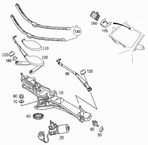
Windshield Wiper Blade
| Part No. | Notes |
|---|---|
| A2208200045 | LHD, single, To Date: 09/03/2000, Replaced by: A2208201845 |
| A2208201845 | LHD, pair, To Date: 09/03/2000 (~EUR 56) |
| A2208200645 | LHD, single AERO, From Date: 09/03/2000, Replaced by A2208200845 |
| A2208200845 | LHD, single AERO, From Date: 09/03/2000, Replaced by A2208201145 |
| A2208201145 | LHD, single AERO, From Date: 09/03/2000, Replaced by A2208201345 |
| A2208201345 | LHD, single AERO, From Date: 09/03/2000, Replaced by A2208201545 |
| A2208201545 | LHD, pair AERO, From Date: 09/03/2000, Replaced by A2208201745 |
| A2208201745 | LHD, pair AERO, From Date: 09/03/2000 (~EUR 60) |
| A2208200145 | RHD, single, To Date: 31/08/1999 |
| A2208201445 | RHD, pair AERO, From Date: 31/08/1999, Replaced by A2208201645 |
| A2208201645 | RHD, pair AERO, From Date: 31/08/1999 (~EUR 60) |
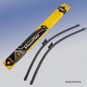
Aftermarket replacement (for LHD vehicles):
- OEM BOSCH Aerotwin A946S 3397118946 680mm (EUR 30)
- VALEO 574317 700mm (EUR 35)
- VALEO 577869 680mm (EUR 25)
- SWF VisioFlex 119438 650mm (EUR 30)
- SWF VisioFlex 119389 700mm (EUR 40)
- CHAMPION KF68/C02 680mm (EUR 50)
- DENSO DF123 700mm (EUR 30)
 |
 |
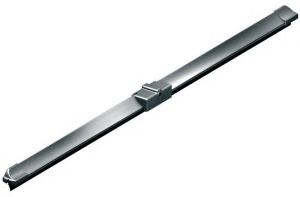 |
Rubber only
It is possible, and much cheaper (~EUR 8 for a pair) to replace only the wiper blade rubber, but make sure that the new blades have the correct form.
Length: 685mm (27”) Width: 6mm
 |
 |
SWISSINT sells high-quality Aerotwin wiper blade rubber refill with graphite coating (Art. Nr AT750). These are made of regular rubber but are simply coated with graphite, a coal-like, semi-metallic element used in pencil lead. When rubber is impregnated with powdered graphite, the blade is able to glide across the glass more smoothly and quietly due to reduced friction. Graphite also helps to protect the rubber from damage and deterioration. BOSCH Aerotwin original rubber is also graphite coated.
Windshield wiper park position
There are two marks on the front windscreen which identify the parked positions of the windscreen wiper blades. The marks are a tiny window in the black undercoating, about a 1.5mm x 10mm clear slit in the black coating. One mark is on the right side and one in the centre of the windscreen. There is no mark on the left side. The two marks can be used to reinstall the wiper mechanisms if they have been removed.
Note it is obvious that the same windscreen is used for LHD and RHD vehicles, hence the marks are only really useful for LHD cars. For RHD cars the position of the right mark can be measured and transferred to the left side as a guide.
If after a full wiping cycle the wiper blades do not park in the park position, the position has to be corrected by reinstalling wiper arms (see instructions below).
| Error Code | Generated By | Description |
|---|---|---|
| B1017 | SAM-FL - Front left signal acquisition and actuation module | Component M6/1 (wiper motor) is not within the park position (terminal 31B). |
Remove/install windshield wiper blades
Wiper system
Networking of components:
Preconditions for function:
- Circuit 15R ON
The windshield wiper system is operated using the combination switch (S4). The following functions are possible:
- Touch wiping: A single wipe is performed. (To do this, push the combination switch (S4) to the detent)
- Intermittent wiper valid up to 31/08/2002: with automatic intermittent wipe control via the rain sensor (B38). To do this, turn the combination switch (S4) to position 1.
- Intermittent wiper valid as of 02/09/2002: with automatic intermittent wipe control via the rain/light sensor (B38/2). To do this, turn the combination switch (S4) to position 1.
Switch positions
At combination switch (S4) position: interval (rain sensor position)
the wiper requests are sent by the rain sensor
(B38) or as of 01/09/2002 by the rain/light sensor (B38/2) via the
overhead control panel control unit (N70).
If another wiper position is selected using the combination switch (S4), the request is transmitted directly to the wiper by the left SAM control module (N10/6).
- Intermittent wiping with slow speed (stage 1, approx. 40 cycles/min.) To do this, turn the combination switch (S4) to position 2.
- Wiping at high speed (stage 2, approx. 60 cycles/min). To do this, turn the combination switch (S4) to position 3.
- Washing: The windshield is wiped with additional water. To do this, push the combination switch (S4) beyond detent.
A data transfer between the left SAM control unit (N10/6) and the overhead control panel control unit (N70) only takes place if the data has changed or one of the two control units has been initialized. Operation is interrupted when "circuit 15R OFF".
The combination switch (S4) information and the requests from the overhead control panel control unit (N70) are provided by the interior CAN. A two-stage standard wiper control is used. It is actuated directly by the left SAM control unit (N10/6).
Wiper system, location of components (up to 31/05/2000)
Wiper system, location of components (as of 01/06/2000)
Wiper function
Slow wiping (stage 1) function sequence:
- The slow windshield wiping function is switched on by turning the combination switch (S4) to position 2
- The position of the combination switch (S4) is read in by the steering column module (N80) and sent to the interior compartment CAN as a message
- The left front SAM control module (N10/6) receives this message and controls the wiper On and Off relay (K40/6kH)
- Circuit 15R is switched via the wiper stage 1 and 2 relay (K40/6kG) to "circuit 53" (slow wiping) by the wiper motor (M6/1) . (The wiper stage 1 and 2 relay (K40/6kG) is then not actuated.)
- The wiper motor operates at slow speed
Fast wiping (stage 2) function sequence:
- The fast windshield wiping function is switched on by turning the combination switch (S4) to position 3
- The position of the combination switch (S4) is read in by the steering column module (N80) and sent to the interior compartment CAN as a message
- The left front SAM control module (N10/6) receives this message and actuates the wiper On and Off relay (K40/6kH) and the wiper stage 1 and 2 relay (K40/6kG)
- Circuit 15R is switched via the wiper stage 1 and 2 relay (K40/6kG) to "circuit 53b" (fast wiping) by the wiper motor(M6/1). (The wiper stage 1 and 2 relay (K40/6kG) is then actuated.)
- The wiper motor runs at high speed
Switching off wiping function:
- If the combination switch (S4) has been turned to position 0, the above-mentioned message is no longer on the interior compartment CAN
- If the wiper motor now reaches the park position, the left front SAM control module (N10/6) ensures that the wiper stops (If switch-off was accomplished from stage 2, the wiper motor is switched back to the slow stage until it reaches the park position)
- The wiper motor stops in the park position
The wiper motor (M6/1) can be switched back to intermittent wiping by the automatic speed reduction.
As of 01/09/2002 the functions anti-lock protection, lock detection, stopping and final wiping are monitored independently by the reversing wiper system (UWA).
Windshield intermittent wiping function
Operational sequence:
- The intermittent wiping function is switched on by turning the combination switch (S4) to position 1.
- The position of the combination switch (S4) is read in by the steering column module (N80) and sent to the interior compartment CAN as a message
- The left front SAM control module (N10/6) receives this message and initiates one wipe cycle (if the wiper was already moving, this wipe cycle is first brought to an end)
- After one wipe cycle, the wiper motor (M6/1) is stopped
- The intermittent pause is started.
- At the end of the pause, the next wipe cycle is executed.
Control of wiper motor
The left front SAM control module (N10/6) controls the wiper motor (M6/1) by means of the wiper stage 1 and 2 relay (K40/6kG) and wiper On and Off relay (K40/6kH) so that the wiper wipes at speed stage 1.
Interruption of intermittent pause
If another wiper function is requested during an intermittent pause, this function is executed without taking the intermittent pause into consideration. After completion of this function, the intermittent pause is started again.
Control of the intermittent pause
The intermittent pause is dependent on the amount of moisture present on the windshield. The left front SAM control module (N10/6) analyses for this purpose the data from the rain/light sensor (B38/2). The exchange of data between the left front SAM control module (N10/6) and the rain/light sensor (B38/2) takes place via the interior compartment CAN and, because the rain/light sensor (B38/2) is not connected directly to the interior compartment CAN, via the overhead control panel control module (N70) as an interface.
In the event of a failure of the rain/light sensor (B38/2) the intermittent time is set to approx. 5 s.
As of 01/06/2000 there is a safety cutout when the front door is open.
System functions
Function prerequisites:
- Circuit 15R ON
Windshield wipers
Switch position I = intermittent = pause duration dependent on quantity of moisture; can be regulated upward to continuous wiping stage 2. Switch position II = stage 1 = continuous wiping 40 cycles/min Switch position III = stage 2 = continuous wiping 60 cycles/min
A two-stage standard wiper control is used. This is actuated directly from the left SAM control module (N10/6).
Data are only transferred between the left SAM control module (N10/6) and the overhead control panel control module (N70) when there is a change to the data, or when one of the two control modules is initialized. The functions are interrupted with "Circuit 15R OFF".
Intermittent wipe (valid as of 01/09/2002)
Continuous wiper control by the rain/light sensor (B38/2). The top priority for switching on the wiper is always assigned to the combination switch (S4). Information such as the vehicle speed, the position of the wiper switch, the ambient light conditions as well as the outside temperature are received by the overhead control panel control module (N70) and processed in the algorithm implemented. The wiper system is actuated via the interior compartment CAN by means of the left SAM control module (N10/6).
The wiper is controlled depending on the particular quantity and frequency of moisture by:
- Individual wipe cycles
- Continuous wipe
- Continuous wiping with the selection of the required wiper speed
The intermittent time is determined by the rain/light sensor (B38/2) (up to stage 2 continuous wiping). If communication with the overhead control panel control module (N70) fails at switch position I the intermittent wiping function is activated. If intermittent wiping is transmitted from position 0, the wipe cycle takes place immediately. After interrupting intermittent wiping by a wiper function, the intermittent pause elapses.
Intermittent times (emergency mode):
- 1st intermittent time T/1 = 5 s 1 s
- 2nd intermittent time T/2 = 1.5 s (T/1 with automatic speed reduction)
The rain/light sensor (B38/2) is activated by switching on the intermittent wiper setting and thus the CAN message generated by the left SAM control module (N10/6) via the overhead control panel control module (N70). The left SAM control module (N10/6) receives the request for intermittent wiping via the interior compartment CAN.
Switch positions (valid as of 01/09/2002)
With the combination switch (S4) position: intermittent (rain sensor position) the requests for the wiper take place via the overhead control panel control module (N70) from the rain/light sensor (B38/2).
If using the combination switch (S4) another wiper setting is selected, the request comes directly from the left SAM control module (N10/6) to the wiper.
The combination switch (S4) information as well as the requests from the overhead control panel control module (N70) are supplied by means of the interior compartment CAN.
Service Information
Intermittent wiping does not function when vehicle is standing still in the rain:
If the combination switch is set to I (intermittent wipe) and the driver or front passenger door is opened, wiping is stopped for safety reasons.
Persons exiting or entering the vehicle are thus protected from splash water.
The windshield wiper will, for example, not come on automatically if the windshield is being cleaned by hand while the ignition is on or the engine is running.
Intermittent wiping is reactivated:
- when the selector lever is moved to D or N (for manual transmissions: when clutch is applied).
- when the combination switch is moved to setting II or III.
Side effect: If the driver gets out to, for example, close the garage door, automatic wiping will be deactivated until a gear is engaged again.
On the vehicle, check whether the customer complaint is a result of the built-in system logic. Explain to the customer how the intermittent wipe function is design to work.
Safety switch-off function (as of 01/06/2000)
Networking of safety cutout Intermittent wipe:
Safety cutout with the intermittent wiping function
The following safety precaution has been incorporated in order to minimize the risks of possible injuries:
- The intermittent wiping function (combination switch in position 1) is suppressed at a vehicle speed of less than 5 km/h as
soon as one of the front doors is opened.
- The function is possible again as soon as both front doors are closed
In order to permit the intermittent wiping function even in the event of a defective door contact switch (S17/3, S17/4), the states of the door contact switches have no effect at speeds above 3 km/h.
Fault analysis:
- Failure of the serial communication interface to the left SAM control module (N10/6) - wiper motor
In the event of a failure of the serial communication interface or a fault report from the wiper motors (e.g.: Hall sensors defective), even when there is as yet no wiper request, an error message is sent from the left SAM control module (N10/6) via the interior compartment CAN to the instrument cluster (A1). The rain sensor and light information are sent from the overhead control panel control module (N70) only in the event of changes.
Wiper startup suppression
Suppression of the wiper function with the driver or passenger door open to prevent accidents.
The wiper function is suppressed when:
- Combination switch (S4) is in position 1 (intermittent stage)
- Driver or passenger door is open
- v < 5 km/h and
- Shift lever position is in P or N
If the driver or passenger door is open at v > 3 km/h, there is no wiper startup suppression.
Actuation of the wiper after a suppressed actuation takes place if:
- the wiper switch has been pressed
- an engaged drive position is detected, or a gear is engaged
- v > 3 km/h
A wipe cycle which has already commenced, is not interrupted. The wiper moves as far as the park position.
Networking
For the safety cutout, the signals of the front door contact switch are needed. These are read in by the rear SAM control module (N10/8) and are sent via the interior compartment CAN to the left front SAM control module (N10/1).
The vehicle speed signal comes from the instrument cluster (A1) via the interior compartment CAN to the left front SAM control module (N10/1).
Fault report of the wiper
If, due to the internal thermal protection, the wiper signals the overload bit, this is signaled by the left SAM control module (N10/6) to the instrument cluster as a wiper fault.
Failure or lack of CAN communication to the overhead control panel
In the event of an incorrect message, the wiper request is rejected and only responded to again with the next correct message. In the event of five incorrect messages, the intermittent wipe control takes place as under 1 (T = 5 s +/- 1 s). If correct communication with the rain/light sensor (B38/2) can be established again, then the system switches back to rain/light sensor mode. No fault is displayed in the instrument cluster.
Timeout of the wiper startup suppression
- For door contacts (rear SAM): doors closed (default value)
- For combination switch (S4) request (electronic ignition switch/steering column module): last valid value
- For v-signal: v > 3km/h
The function can be coded out.
Anti-lock protection, lock detection, stopping, final wiping
The functions are carried out independently by the UWA (reversal wiper system).
Special case for wiper startup suppression
A wipe cycle that has already been initiated (with request via combination switch (S4) "position 1" or "final wiping") is not interrupted by opening the driver or passenger doors. The wiper movement takes place until it reaches the park position. Further wiper requests (with combination switch (S4) "position 1") are, however, suppressed with the above-described criteria.
Wiper system automatic speed reduction function
The automatic speed reduction has an effect on the functions (valid as of 01/09/2002):
- Wiping in stage "1"
- Wiping in stage "2"
If the vehicle speed drops below 5 km/h, then the left front SAM control module (N10/6) switches the wiper motor (M6/1) from these functions back to intermittent wiping. The intermittent pause is controlled in this case by the rain/light sensor (B38/2).
Switching back to the selected wiper stage (valid until 31/08/2002)
If with increasing vehicle speed the value of 8 km/h is exceeded, the left front SAM control module (N10/6) switches the wiper motor (M6/1) automatically back again to the wiper stage ("1" or "2") set at the combination switch (S4).
The vehicle speed signal required for the speed reduction is received at the left front SAM control module (N10/6) via the interior compartment CAN from the instrument cluster (A1).
The speed reduction can be reset manually by pressing the combination switch (S4) again for each desired function.
Switching back to the selected wiper stage (valid as of 01/09/2002)
If a rain/light sensor (B38/2) is provided, the system always switches back to rain sensor mode. For this purpose, the rain/light sensor (B38/2) must be activated and "circuit 15 ON". If the rain/light sensor (B38/2) is present but defective, the standard way of switching back (switching back one stage) is carried out.
Instantaneous status: v-back-switching not in USA.
Anti-lock protection for wiper motor function
Lock-up recognition
Lockup of the wiper motor (M6/1) is detected by the left front SAM control module (N10/6) by the lack of signals from the cam switch.
Anti-lock protection for wiping in "stage 2" function
If this signal from the cam switch is missing for more than 4 s, then the left front SAM control module (N10/6) switches the wiper motor (M6/1) to "stage 1".
If the signal is still missing for a further 8 s, then the left front SAM control module (N10/6) switches the wiper motor (M6/1) off.
Anti-lock protection for the functions one-touch wiping,
intermittent wiping, washing and wiping in "stage 1"
With these functions the left front SAM control module (N10/6) switches the wiper motor (M6/1) off, if the signals from the cam switch do not appear for more than 12 seconds.
In all cases, the anti-lock protection is canceled if: the corresponding function is requested again by pressing the combination switch (S4) or "circuit 15R" is switched on again.
If the wiper motor (M6/1) still locks after canceling the anti-lock protection, the wiper motor (M6/1) is switched off again as described above.
Slowing down wiper motor function
Following the completion of a wiping operation, the wipers must come to a stop in the park position.
Stopping wiper motor
To stop the motor, the wiper On and Off relay (K40/6kH ) is switched off by the left front SAM control module (N10/6). Through the opening of this relay:
- The connection circuit 53 for the wiper motor (M6/1) is disconnected from the voltage supply circuit 15R
- The connection circuit 53 for the wiper motor (M6/1) is connected to ground via an electronic switch (FET) of the SAM; this short-circuits the motor
- This short circuit decelerates the motor (eddy current dynamometer)
Prerequisites for stopping wiper motor
The stopping of the wiper motor (M6/1) is only initiated if:
- The wiper motor is switched off (combination switch (S4) in position 0) or
- Intermittent wiping is switched on (combination switch (S4) in position 1) and an intermittent pause has just started
- The cam switch is closed, and thus the park position has been reached
In order to detect the park position, the wiper motor (M6/1) has a cam switch. When the motor runs through the park position, the cam switch is actuated.
The signal from the cam switch is interrogated continuously by the left front SAM control module (N10/6) .
Wiper motor
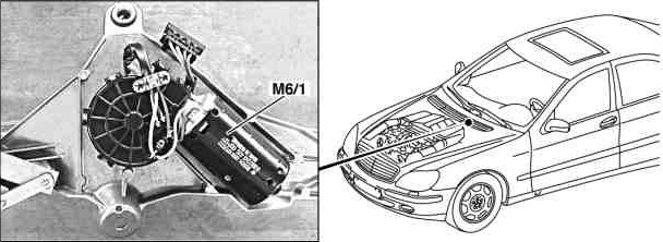
|
|
The wiper motor is located in the water trough underneath the windshield.
The purpose of the wiper motor is to drive the windshield wipers with two speed stages and detect exact end position of the wipers.
The drive for the windshield wipers consists of an electric motor with three brushes, gear and the cam switch on the output shaft.
Function
The wiper motor (M6/1) is a DC motor with three brushes. Depending on which pair of brushes is energized, the wiper motor (M6/1) operates at different speeds.
Cam switch
The cam switch is closed when the wiper motor (M6/1) is in the rest position. With each wiping cycle the cam switch opens and closes when the non-actuated state is reached. This generates the signal c. 31b.
Using the circuit 31b signal, it is possible to determine whether the wiper motor (M6/1)
- is operating correctly,
- locked up,
- or in the rest position.
Wiper rest heater function
Interlinkage of components:
Prerequisites for operation of wiper rest heater:
- Engine: ON
Function
At outdoor temperatures below 5 °C the windshield is heated directly in the area where the wiper blades rest by the wiper rest heater (R2/10).
If the outdoor temperature increases to above 7°C the wiper rest heater is switched off.
Actuation of wiper rest heater (R2/10)
When switch-on conditions are fulfilled the left front SAM control module (N10/6) actuates the wiper rest heater relay (K40/6kA) on the left front fuse and relay module (K40/6). The wiper rest heater relay (K40/6kA) then switches on circuit 30 to the wiper rest heater (R2/10).
Required data:
- Outdoor temperature: The outdoor temperature sensor (B14) is read in directly by the left front SAM control module (N10/6) to check the outdoor temperature.
- Status of circuit 61 (generator): The status of c.61 is read in by the right front SAM control module (N10/7) and relayed to the left front SAM control module (N10/6) via the CAN bus (passenger compartment).
Windshield washer function
The windshield is wiped while water is sprayed.
Function sequence
- Press combination switch (S4) beyond catch point
- The signal from the combination switch (S4) is read in by the jacket tube module (N80) and the corresponding message is transferred to the CAN bus (passenger compartment),
- The left front SAM control module (N10/6) and right front SAM control module (N10/7) receive this message.
- The left front SAM control module (N10/6) starts the wiper motor (M6/1), the right front SAM control module (N10/7) actuates the windshield washer fluid pump (M5/1):
- The windshield washer fluid pump (M5/1) runs as long as the combination switch (S4) is actuated.
- When the combination switch (S4) is released, the wiper motor (M6/1) continues to run to wipe off the remaining water. The number of wiping cycles depends on the time the combination switch (S4) was activated:
- If actuated less than 1 second the wiper wipes one more time,
- If actuated longer, 3 wiping cycles are completed.
- After completion of the wiping operation the wiper motor (M6/1) is decelerated.
The wiper motor (M6/1) runs in stage 1 for washing. Wiping is accomplished at speed 2 only when the wipers were simultaneously set to speed 2.
Control of washer pump
The windshield washer fluid pump (M5/1) is actuated directly by the right front SAM control module (N10/7). During the washing operation the windshield washer fluid pump (M5/1) is connected to ground by an electronic switch (transistor) in the control module.
In the event of an overload the pump is switched off by the right front SAM control module (N10/7).
Windshield washer, location of components
Windshield washer pump

|
|
The purpose of the pump is to pump windshield washer fluid for washing the windshield.
The windshield washer fluid pump (M5/1) is driven by a DC motor integrated into the pump housing.
Function
For operation of the windshield washer the windshield washer fluid pump (M5/1) pumps the windshield washer fluid from the windshield washer reservoir through the hoses and windshield washer nozzles to the windshield. For this purpose ground is connected to the motor for the windshield washer fluid pump (M5/1) by the right front SAM control module (N10/7).
This actuation is accomplished directly by an electronic switch (transistor) in the control module and not by a relay.
Coolant/washer fluid level voltage coding
The circuit shown in the figure is used to determine the level of the coolant and windshield washer fluid. The coolant level indicator switch (S41) and the windshield washer fluid level indicator switch (S42) are connected in series. Both switches are read in via two lines by the right front SAM control unit (N10/7).
The figure illustrates the status of the switches when the coolant and washer fluid are at the correct levels.
Voltage coding:
For voltage coding the resistors r1 and r2 are connected in parallel with the switches s1 and s2. (The values from r1 and r2 must be different.) When the switches are open, these resistors, together with r3 of the right front SAM control unit (N10/7), form a voltage divider which is supplied with the constant voltage Uconst. The voltage Ue at the input of the right front SAM control unit (N10/7) therefore depends on the positions of the switches and the values of the resistors. With the two switches, there are therefore four possible switch combinations (see table). Each of these combinations results in a different value for voltage Ue at the input of the right front SAM control unit (N10/7).
Evaluation
The voltage Ue is applied at the input of the ADC (analog-to-digital converter) of the right front SAM control unit (N10/7). The ADC (analog-to-digital converter) converts the analog voltage into a digital value. This is necessary since the processor of the right front SAM control unit (N10/7) can only work with digital values.
The processor compares the values to the threshold values stored in memory and if necessary, passes an appropriate message (coolant and/or washer fluid level too low) on the CAN (passenger compartment). The instrument cluster (A1) reads this message and controls the multifunction display (A1p13) accordingly.
If the resistance values and the voltage Uconst are known, Ue
can be calculated using the following formula:
Ue = Uconst * (r1 + r2 )/(r1 + r2 + r3)
Assignment of switch status/warning messages:
The following table shows the warning messages which appear according to the status of the switches. These messages can be acknowledged by pressing the reset button on the instrument cluster (A1).
| Status Coolant | Status Washer fluid | Warning on the multifunction display |
|---|---|---|
| open | closed | No message |
| open | open | "CHECK WASHER FLUIDLEVEL" |
| closed | closed | "CHECK COOLANT LEVEL" |
| closed | open | "CHECK COOLANT LEVEL" (The message "CHECK WASHER FLUID LEVEL" has a lower priority.) |
If there is an open circuit in the wiring or if a sensor fails, no message appears on the multifunction display (A1p13). A fault is stored, however, in the fault memory of the right front SAM control unit (N10/7).
Windshield washer nozzle and windshield washer nozzle hose heater function
The heated windshield washer nozzle (R2/1) and washer nozzle hose heater (R2/11) are switched on automatically when:
- C. 61 ON (engine: ON) and
- outdoor temperature less than 5°C is recognized.
Switch-off is accomplished:
- C.61 OUT (engine: OFF) or
- outdoor temperature greater than 7°C are recognized.
If the values (outdoor temperature, c.61) are not present or not logical the heater elements are not switched on!
Control of heater elements
The heater elements for the heated windshield washer nozzle (R2/1) and washer nozzle hose heater (R2/11) are connected in parallel. Control of the heated windshield washer nozzles (R2/1) and washer nozzle hose heater (R2/11) is accomplished directly from the right front SAM control module (N10/7). For this purpose the SAM completes circuit 30 to the heater elements.
Required data:
- The ambient temperature is recorded by the ambient temperature display temperature sensor (B14). The left front SAM control module (N10/6) reads in the sensor and sends the measured value as a message on the CAN (interior).
- The status of c.61 (generator G2) is read in directly by the right front SAM control module (N10/7).
Remove and install wiper arm
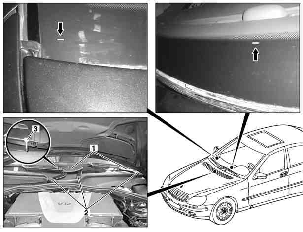
|
|
- Move wiper system to parked position
- Open engine hood and move to vertical position
- Unscrew nuts (2)
- Remove wiper arm (1). Installation: The wiper blade must rest directly on the mark (arrow) in the silk screen print of the windshield. On model 215, 220 as of the use of aero wipers, the retainer (3) is to be removed with the use of new wiper blades.
- Install in the reverse order
- Check operation of windshield wipers
Torque specifications:
- Nut on wiper arm: 33 Nm
Remove/install wiper system
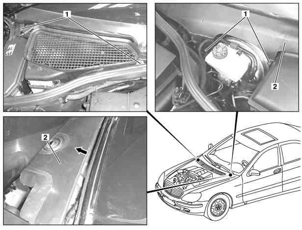
|
|
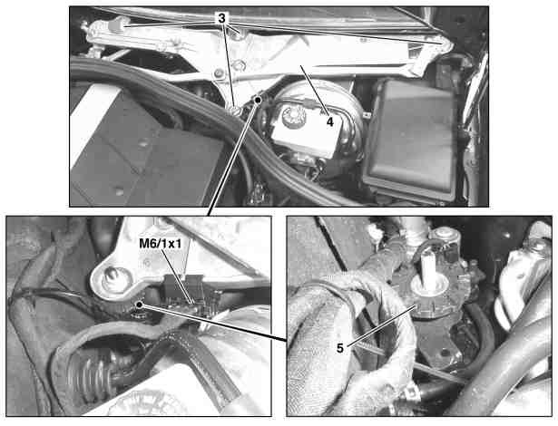
|
|
Removing:
- Remove wiper arms
- Remove 4 expansion rivets (1)
- Remove water repellent (2) upward out of fold (arrow)
- Unscrew 4 nuts (3). Do not twist knurled nut (5), otherwise the incline angle of the wiper system is changed.
- Disconnect connector (M6/1x1) at wiper motor
- Remove wiper system (4)
Installing:
- Insert wiper system (4)
- Screw in 4 nuts (3)
- Move wiper motor to parked position
- Install water repellent (2)
- Install wiper arms
- Check operation of windshield wipers
Torque specifications:
- Nut, wiper system: 20 Nm
Remove/install wiper motor

|
|
Remove:
- Open engine hood and move to vertical position
- Remove wiper system
- Unscrew nut of wiper motor shaft (1)
- Pull off crank (2) with wiper linkage
- Unclip connector at bracket (4)
- Remove screws/bolts at wiper motor (3)
- Remove wiper motor (M6/1)
Install:
- Move wiper motor (M6/1) to parked position
- Insert wiper motor (M6/1)
- Screw in wiper motor (3) screws/bolts
- Unclip connector at bracket (4)
- Align crank (2) in angle (A) to top rib of wiper motor bracket
- Turn nut on wiper motor shaft (1)
- Install wiper system
- Close engine hood
- Check operation of windshield wipers
Torque specifications:
- Bolt on wiper motor mount: 9 Nm
- Nut on wiper motor shaft: 19 Nm
Test and adjustment values for windshield wiper:
- Dim Angle "A" between crank and rib: 74°
Move wiper motor to parking position
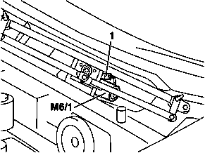 |
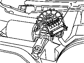 |
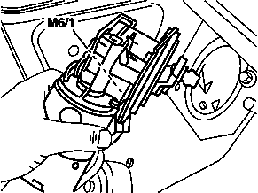 |
- Connect wiper motor (M6/1) to wiper motor connector (1)
- Hold wiper motor (M6/1) using the left hand.
- Switch on ignition.
- Set combination switch to "stage 1".
- Turn combination switch back to "level 0".
- If the wiper motor (M6/1) is in the park position, switch off the ignition.
- Detach wiper motor connector (1) from wiper motor (M6/1).
Wiper arm adjustment
By checking the angle of incidence of the wiper arms in parked position and reversing position, it can be assessed whether one wiper arm, both wiper arms or the wiper system are to be adjusted. The wiper arms are adjusted in case the check values deviate from the tolerance range in reversing position or in case the check values deviate from the tolerance range in reversing position and parked position.
The angle of incidence is changed by twisting (crossing over) the wiper arms with the aid of the adjustment lever. The angle of incidence of the wiper arm always has to be adjusted in parked position.
In doing so the angle of incidence in parked position and reversing position changes by the same amount. The angle of incidence of the wiper arm to be adjusted is changed by at least the value of the tolerance deviation in reversing position. To make sure that both adjustment values lie within the tolerance range, the angle of incidence has to be checked again in parked position and corrected if necessary. The windshield wiper system is adjusted in case check values of both wiper arms deviate from the tolerance range in parked position.
Check wiper arms and adjust
Shown on MODEL 211, windshield wiper system in reversing position:
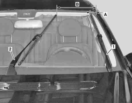
|
|
Caution:
- When working on raised wiper arm, ensure that this does not fall onto the windshield. Otherwise windshield will be damaged.
- When moving the windshield wiper system out of the park position or changing from reversing position to parked position, ensure that the wiper arm makes no direct contact with the windshield. Otherwise, the windshield may be scratched.
Check:
- Manually position windshield wiper system in reversing position
- Remove wiper blade from driver-side wiper arm (1). The driver-side wiper arm (1) must not be moved.
- Check driver-side wiper arm (1). The reversing position for the driver-side wiper arm (1) corresponds to the distance from the driver-side wiper blade to the A-pillar (A). Distance between driver-side wiper blade and A-pillar (A) approx. 50 mm.
- Remove wiper blade from passenger-side wiper arm (2). The passenger-side wiper arm (2) must not be moved.
- Check passenger-side wiper arm (2). Model 211: The reversing position of the passenger-side wiper arm (2) corresponds to the distance from the passenger-side wiper blade to the A-pillar (B) of approx. 350 mm.
Clean:
- Clean wiper blade fixtures on driver-side wiper arm (1) and passenger-side wiper arm (2) using a clean cloth
- Cover driver-side wiper arm (1) using suitable aids (scratch protection)
- Measure angle of incidence of wiper arm (1) to windshield, note this down and compare test value with adjustment value.
- Cover passenger-side wiper arm (2) using suitable aids (scratch protection)
- Measure angle of incidence of wiper arm (2) to windshield, note this down and compare test value with adjustment value.
Adjust:
- Adjust angle of incidence of driver-side wiper arm (1) in park position. If the test values deviate from the tolerance range in the reversing position or in the parked and reversing position. The driver-side wiper arm (1) must be adjusted by at least the value of the tolerance deviation in the reverse position.
- Adjust windshield wiper system. In the event that the check values of the wiper arm (1) deviate from the tolerance range in park position.
- Cover driver-side wiper arm (1) using suitable aids and move windshield wiper system out of park position.
- Install driver-side wiper blades.
- Adjust angle of incidence of passenger-side wiper arm (2) in park position. If the test values deviate from the tolerance range in the reversing position or in the parked and reversing position. The passenger-side wiper arm (2) must be adjusted by at least the value of the tolerance deviation in the reverse position.
- Adjust windshield wiper system. In the event that the check values of the wiper arm (2) deviate from the tolerance range in park position.
- Cover the passenger-side wiper arm (2) using suitable aids and move the windshield wiper system out of park position.
- Install wiper blades.
Test and adjustment values of wiper arms:
- Angle of incidence of wiper arm on driver-side in reversing position:
- Left-hand drive vehicle: –1,0°...–6,0°
- Right-hand drive vehicle: +1,0°...+6,0°
- Angle of incidence of wiper arm on passenger-side in reversing position:
- Left-hand drive vehicle: –0,5°...–4,0°
- Right-hand drive vehicle: +0,5°...+4,0°
- Angle of incidence of wiper arm on driver-side in parked position:
- Left-hand drive vehicle: +2,0°...+6,0°
- Right-hand drive vehicle: –2,0°...–6,0°
- Angle of incidence of wiper arm on passenger-side in parked position
- Left-hand drive vehicle: +2,0°...+6,0°
- Right-hand drive vehicle: –2,0°...–6,0°
Torque specifications:
- Nut, wiper system: 20 Nm
Check wiper arms
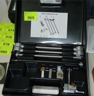 |
 |
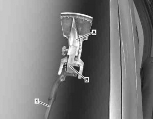 |
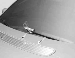 |
- Remove angle gauge (A) from the adjustment tool set.
- Insert adapter (B) into the guide (arrow) of the angle gauge (A) and fasten with the screw/bolt to angle gauge (A).
- Position wiper arm (1) to be adjusted in reversing position.
- Slide adapter (B) together with angle gauge (A) onto wiper blade mount of wiper arm (1) to be adjusted and attach with screw/bolt.
- Lower wiper arm (1) to be adjusted carefully onto windshield. All three contact points at the foot of the angle gauge (A) must make contact with the windshield.
- Read off the angle of incidence of the driver-side wiper arm (1) in reversing position on the scale of the angle gauge (A), note down and compare to the corresponding specified value.
- Raise wiper arm (1) to be adjusted and remove adapter (B) together with angle gauge (A).
- Raise wiper arms (1), cover with appropriate aids (scratch protection) and set down on windshield.
- Move wiper arms (1) to park position and remove aid (scratch protection) from wiper arms (1).
- Repeat test procedures 3 to 6 at the wiper arm (1) to be adjusted in parked position.
Adjust wiper arms
Adjustment of the wiper arm angle of incidence is always done in the parked position. If the check values deviate from the tolerance range adjustment occurs both in reversing position and parked position. In doing so, the driver-side wiper arm or front passenger-side wiper arm is adjusted by at least the value of the tolerance deviation in reversing position.
Use adjustment levers (Z4) from adjustment tool set.
- Remove angle gauge (A) and adjustment lever (Z4) from adjustment tool set.
- Insert adapter into guide of angle gauge (A) and fix in place with screw/bolt at angle gauge (A).
- Slide adapter together with angle gauge (A) onto wiper blade mount of wiper arm to be adjusted and attach with screw/bolt.
- Lower wiper arm to be adjusted carefully onto windshield. All three contact points at the foot of the angle gauge (A) must make contact with the windshield.
- Place adjustment levers (Z4) as far from each other as possible on the wiper arm to be adjusted. The wiper arm is twisted with the aid of the adjustment lever (Z4) that was positioned close to the angle gauge (A). The second adjustment lever (Z4) is used as a counterholder.
- Press adjustment lever (Z4) in required direction until the wiper arm to be adjusted is at least distorted by the value of the tolerance deviation in the reversing position.
- Remove adjustment lever (Z4) from wiper arm to be adjusted.
- Read off angle of incidence for adjusted wiper arm on scale of angle gauge (A), note it down and compare against the test and adjustment values, adjust again if necessary.
- Detach angle gauge (A) with adapter from adjusted wiper arm.
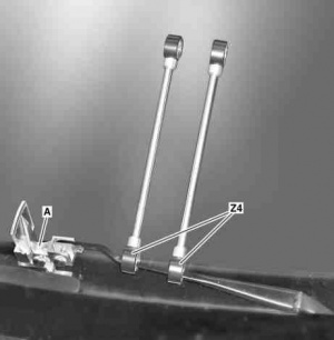 |
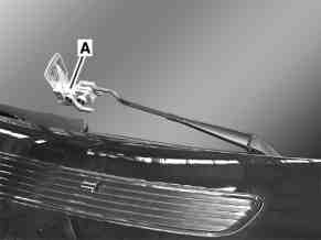 |
Adjusting wiper system
The wiper system may only be adjusted if the test values of both wiper arms deviate from the tolerance range in park position.
- Install angle gauge (A) to driver-side wiper arm (1).
- Open hood.
- Remove spreader clip (2) and push back water collector (3) until jam nut (4) is accessible.
- Loosen jam nut (4) and turn adjusting nut (5) until the correct adjustment value is shown on the dial of the angle gauge (A).
- Tighten locknut (4).
- Install spreader clip (2). Replace damaged expansion clip (2).
- Close hood and remove angle gauge (A) from driver-side wiper arm (1).
Shown on model 215:
Issues
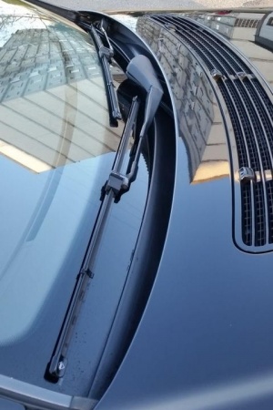
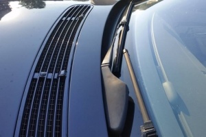 |
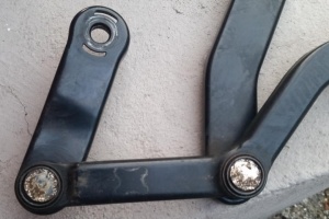 |
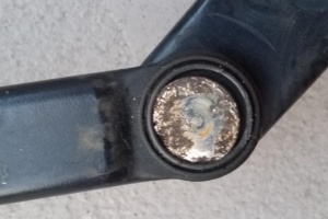 |
