Wheel alignment: Difference between revisions
(→Adjust toe at the rear axle (RA): added more info from WIS) |
|||
| (16 intermediate revisions by the same user not shown) | |||
| Line 4: | Line 4: | ||
===Tutorials=== | ===Tutorials=== | ||
{| | {| | ||
|{{#ev:youtube|https://www.youtube.com/watch?v=kOBxIbbvyLo|320|left|Four wheel alignment using a laser machine | |{{#ev:youtube|https://www.youtube.com/watch?v=kOBxIbbvyLo|320|left|Four wheel alignment using a laser machine|frame}} | ||
|{{#ev:youtube|https://www.youtube.com/watch?v=RoZ6CRYDgY4|320|left|MB guide to effective wheel alignment|frame}} | |||
|{{#ev:youtube|https://www.youtube.com/watch?v=RoZ6CRYDgY4|320|left|MB guide to effective wheel alignment | |||
|} | |} | ||
| Line 19: | Line 16: | ||
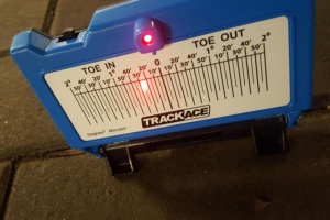
|[[File:W220_toe-in_measurement_trackace.jpg|thumb|none|DIY toe-in measurement using trackace]] | |[[File:W220_toe-in_measurement_trackace.jpg|thumb|none|DIY toe-in measurement using trackace]] | ||
|[[File:W220_trackace_front_wheel_alignment.jpg|thumb|none|Trackace toe-in measurement (reads ~25')]] | |[[File:W220_trackace_front_wheel_alignment.jpg|thumb|none|Trackace toe-in measurement (reads ~25')]] | ||
|{{#ev:youtube|https://www.youtube.com/watch?v=5VCo72Fyrao|320|left|Trackace DIY Laser Wheel Alignment|frame}} | |||
|} | |||
{| | |||
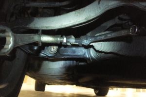
|[[File:W220_wheel_alignment_wrench_13mm_21mm.jpg|thumb|none|To adjust use 21mm and 13mm wrenches]] | |||
|} | |} | ||
==== Airmatic height setting ==== | |||
Toe-in on a raised and lowered car ([[Airmatic]] level adjustment) can differ. | |||
On some cars we have observed that it differs just a little (around 5') while on other W220 vehicles toe-in on a raised car can be even 20' larger than on a lowered car. | |||
This should be taken into account when performing a toe-in adjustment. | |||
I.e., the toe-in should be adjusted for the Airmatic height setting that is usually used for driving. | |||
If both height settings are used equally, then the toe-in should be set to have the same distance from the targeted toe-in (0° 15') on a lowered and raised car. | |||
=== Adjust toe at the front axle (FA) === | === Adjust toe at the front axle (FA) === | ||
| Line 67: | Line 76: | ||
|} | |} | ||
=== Adjust toe at the front axle (FA) === | === Adjust toe at the rear axle (RA) === | ||
<!-- AR40.20-P-0261I Adjust rear-axle toe | |||
MODEL 215 | |||
MODEL 220 | |||
except CODE (979) Special protection version | |||
except CODE (Z07) Top protection | |||
4.5.07 | |||
--> | |||
{| | |||
|[[File:W220_rear_tie_rod.png|400px]] | |||
|Shown on model 220: | |||
* 60 Tie rod | |||
* 60a Cam bolt | |||
* 60b Rubber bushing | |||
|} | |||
{| | |||
|Eccentric rubber mount: | |||
* 60 Tie rod | |||
* 60c Rubber bushing | |||
* +X = +1.5mm | |||
* -X = -1.5 mm | |||
|[[File:W220_rear_tie_rod_eccentric_rubber_mount.png|400px]] | |||
|} | |||
# Check vehicle level at front and rear axle with electronic inclination meter and adjust, if necessary | |||
# Loosen nut of cam bolt (60a) | |||
# Adjust toe with cam bolt (60a) | |||
# Tighten the nut of the cam bolt (60a) | |||
Rear axle toe check values: 0° 41'(± 14') | |||
This is an average value. More specific rear toe angle values (depending on vehicle level) are listed in WIS. | |||
=== Adjust camber and caster at the front axle (FA) === | |||
<!-- AR40.20-P-0263I, Adjust camber and caster at the front axle, 19.9.11 | <!-- AR40.20-P-0263I, Adjust camber and caster at the front axle, 19.9.11 | ||
MODEL 215 | MODEL 215 | ||
| Line 110: | Line 155: | ||
* Tighten nut (19b). The repair bolt (19c) must not turn after fixing. When tightening the nut (19b) counterhold the repair bolt (19c) otherwise the lock tabs in the rubber mount of the torque strut (18) or spring control arm (17) will be sheared off. | * Tighten nut (19b). The repair bolt (19c) must not turn after fixing. When tightening the nut (19b) counterhold the repair bolt (19c) otherwise the lock tabs in the rubber mount of the torque strut (18) or spring control arm (17) will be sheared off. | ||
Torque specification: | |||
* Repair kit nut: 120 Nm | |||
<!-- Incomplete - the table values in WIS not understandable --> | |||
Check values: | |||
* Camber check value: 1°N±20' (tolerated difference between left/right: 0°20') | |||
* | * Caster check value: 9°11'±30' (tolerated difference between left/right: 0°30') | ||
These are average check values. More specific values (depending on vehicle level) are listed in WIS. | |||
==== Install repair bolt ==== | |||
<!-- AR40.20-P-0322-01I Install repair bolt --> | |||
{| class="wikitable" style="margin: auto;" | |||
|+Camber adjustments | |||
|- | |||
!style="text-align:left;"|Spring link in mm | |||
!Camber change | |||
!Torque strut in mm | |||
!Caster change | |||
|- | |||
| +4 | |||
| -26' | |||
| ±0 | |||
| +35' | |||
|- | |||
| -4 | |||
| +26' | |||
| ±0 | |||
| -35' | |||
|} | |||
{| class="wikitable" style="margin: auto;" | |||
|+Caster adjustments | |||
|- | |||
!style="text-align:left;"|Spring link in mm | |||
!Camber change | |||
!Torque strut in mm | |||
!Caster change | |||
|- | |||
| ±0 | |||
| -5' | |||
| +4 | |||
| -46' | |||
|- | |||
| ±0 | |||
| +5' | |||
| -4 | |||
| +46' | |||
|} | |||
{| class="wikitable" style="margin: auto;" | |||
|+Caster adjustments | |||
|- | |||
!style="text-align:left;"|Spring link in mm | |||
!Camber change | |||
!Torque strut in mm | |||
!Caster change | |||
|- | |||
| +4 | |||
| -31' | |||
| +4 | |||
| -11' | |||
|- | |||
| -4 | |||
| +31' | |||
| -4 | |||
| +11' | |||
|- | |||
| +4 | |||
| -21' | |||
| -4 | |||
| +1°22' | |||
|- | |||
| -4 | |||
| +21' | |||
| +4 | |||
| -1°22' | |||
|} | |||
1. Jack up vehicle at the front (the suspension must be fully rebounded). | |||
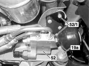
2. Vehicles with ABC suspension: To remove the production bolt (19a) of the right front spring link, detach the bracket of the valve unit for pressure supply (52) from the front axle carrier. | |||
{| | |||
|[[File:W220_production_bolt_abc_suspension.png]] | |||
| | |||
* 19a - Production bolt | |||
* 52 - Pressure supply valve unit | |||
* 52/1 - Mounting bolts of the bracket of the valve unit for pressure supply | |||
|} | |||
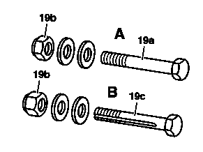
3. To adjust the camber and caster, the respective production bolt (19a) on the torque strut or spring link must be replaced with a repair bolt (19c). | |||
{| | |||
|[[File:W220_front_suspension_standard_and_repair_bolt.png]] | |||
| | |||
* A - Standard bolted connection | |||
* B - Repair bolted connection | |||
* 19a - Production bolt | |||
* 19c - Repair bolt | |||
* 19b - Nut | |||
|} | |||
{| | |||
|[[File:W220_front_suspension_standard_and_repair_bolt_bearings.png]] | |||
| | |||
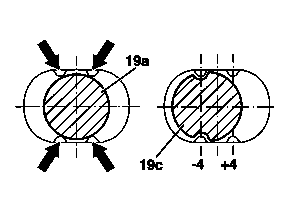
The standard bolt (19a) is centered by the bumps (arrows) in the bearing of the torque strut or spring link. Grooves in the repair bolt (19c) permit it to be installed in the bearing on either the right or left side, allowing the torque strut or spring link to be adjusted by a distance of 4 mm to the inside or outside. | |||
The repair bolt (19c) must not be turned after the torque strut or spring link has been fixed in the bearing. Do not tighten the nut yet so that the rubber mounts on the torque strut and spring link can turn when the suspension is compressed and rebounded. | |||
|} | |||
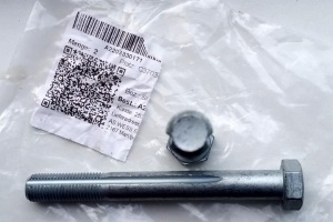
[[File:W220_A2203330171_fitted_bolt.jpg|thumb|none|Fitted bolt (A2203330171)]] | |||
=== Adjust camber at the rear axle (RA) === | |||
<!-- AR40.20-P-0331I Check rear axle camber 7.11.97 | |||
MODELS 215, 220 | |||
--> | |||
The camber on the rear axle is not adjustable. | |||
If substantial deviations in the rear axle camber are found, the cause may be one of the following: | |||
* Too great a difference in vehicle level between right and left-hand sides of vehicle. | |||
* Accident damage on frame floor. Level differences at mounting points for rear axle carrier between left and right body side. Experience shows that bending caused by an accident also has an effect on the toe. | |||
Rear camber check value: 1°6'N±30' (tolerated difference between left/right: 0°30') | |||
This is an average check value. More specific values (depending on vehicle level) are listed in WIS. | |||
Latest revision as of 14:19, 29 July 2025
Wheel Alignment
http://www.jltechno.com/en/alignment-data-lookup
Tutorials
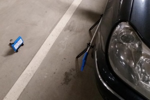
DIY toe-in measurement
Trackace DIY laser wheel alignment tracking gauge (~100 EUR) is a cheap, simple and precise measurement tool to measure front wheel's toe-in/toe-out.
According to W220 specifications, the front wheels should have toe in of 0° 15'(± 10').
 |
 |
 |
Airmatic height setting
Toe-in on a raised and lowered car (Airmatic level adjustment) can differ. On some cars we have observed that it differs just a little (around 5') while on other W220 vehicles toe-in on a raised car can be even 20' larger than on a lowered car. This should be taken into account when performing a toe-in adjustment. I.e., the toe-in should be adjusted for the Airmatic height setting that is usually used for driving. If both height settings are used equally, then the toe-in should be set to have the same distance from the targeted toe-in (0° 15') on a lowered and raised car.
Adjust toe at the front axle (FA)
Adjust:
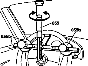
- Switch off easy entry/exit for driver seat and steering wheel. Otherwise the driver seat and steering wheel move into a different position if the driver door is opened or closed for example. The upper frame may be damaged when the holding device (055) is installed. Switching off takes place via the buttons on the steering wheel in the "comfort" menu of the multifunction display.
- Swivel sun visor to one side and fix steering wheel in center position using retainer (055). Carefully mount retainer (055), in order to avoid damaging the steering wheel or the headliner.
- Check center position of steering gear and steering wheel. The steering gear is centered when the marking on the cap is aligned with the mark on the control valve housing. If necessary, shift steering wheel.
- Install wheel spreader (030) at the front in the direction of travel on the inside of the wheel (in the direction of travel). The elastic bearing of the transverse control arm and steering linkage produces a correspondingly large toe value that is reduced to the correct dimension in the ready to-drive condition.
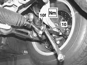
- Counterhold tie rod (10) at the hexagon and loosen jam nut (10f).
- Rotate the tie rods (10) to adjust the toe angle.
- Tighten jam nut (10f)
- Remove retainer (055).
- Remove wheel spreader (030).
- Check bellows for twisting and align if necessary.
Front axle toe check values: 0° 15'(± 10')
Torque spec:
- Lock nut, tie rod to inner tie rod: 60 Nm
 |
|
 |
Shown on model 220 without 4MATIC
|
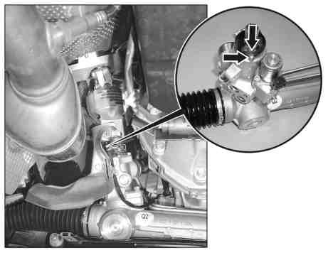 |
Shown on model 220 with 4MATIC
|
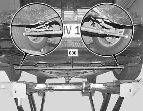 |
Shown on model 220 without 4MATIC
|
Adjust toe at the rear axle (RA)
|
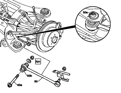
Shown on model 220:
|
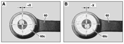
Eccentric rubber mount:
|
|
- Check vehicle level at front and rear axle with electronic inclination meter and adjust, if necessary
- Loosen nut of cam bolt (60a)
- Adjust toe with cam bolt (60a)
- Tighten the nut of the cam bolt (60a)
Rear axle toe check values: 0° 41'(± 14')
This is an average value. More specific rear toe angle values (depending on vehicle level) are listed in WIS.
Adjust camber and caster at the front axle (FA)
Adjust:
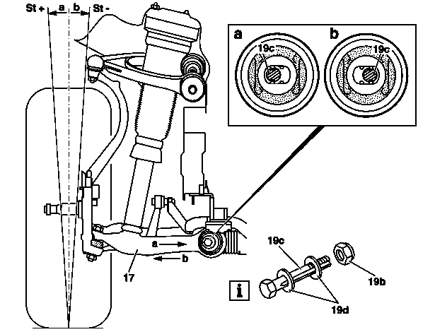
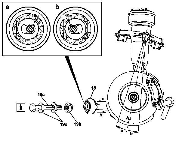
- Install repair bolt (19c). Screw on nut (19b) until it abuts, but do not tighten yet so that the rubber mount of the torque strut (18) or spring control arm (17) can twist when the vehicle is rocked to settle the suspension.
- Recheck vehicle level at front axle after adjusting the camber and caster. The vehicle level must match the dimension established during the initial measurement.
- Tighten nut (19b). The repair bolt (19c) must not turn after fixing. When tightening the nut (19b) counterhold the repair bolt (19c) otherwise the lock tabs in the rubber mount of the torque strut (18) or spring control arm (17) will be sheared off.
Torque specification:
- Repair kit nut: 120 Nm
Check values:
- Camber check value: 1°N±20' (tolerated difference between left/right: 0°20')
- Caster check value: 9°11'±30' (tolerated difference between left/right: 0°30')
These are average check values. More specific values (depending on vehicle level) are listed in WIS.
Install repair bolt
| Spring link in mm | Camber change | Torque strut in mm | Caster change |
|---|---|---|---|
| +4 | -26' | ±0 | +35' |
| -4 | +26' | ±0 | -35' |
| Spring link in mm | Camber change | Torque strut in mm | Caster change |
|---|---|---|---|
| ±0 | -5' | +4 | -46' |
| ±0 | +5' | -4 | +46' |
| Spring link in mm | Camber change | Torque strut in mm | Caster change |
|---|---|---|---|
| +4 | -31' | +4 | -11' |
| -4 | +31' | -4 | +11' |
| +4 | -21' | -4 | +1°22' |
| -4 | +21' | +4 | -1°22' |
1. Jack up vehicle at the front (the suspension must be fully rebounded).
2. Vehicles with ABC suspension: To remove the production bolt (19a) of the right front spring link, detach the bracket of the valve unit for pressure supply (52) from the front axle carrier.
|
|
3. To adjust the camber and caster, the respective production bolt (19a) on the torque strut or spring link must be replaced with a repair bolt (19c).
|
|
Adjust camber at the rear axle (RA)
The camber on the rear axle is not adjustable. If substantial deviations in the rear axle camber are found, the cause may be one of the following:
- Too great a difference in vehicle level between right and left-hand sides of vehicle.
- Accident damage on frame floor. Level differences at mounting points for rear axle carrier between left and right body side. Experience shows that bending caused by an accident also has an effect on the toe.
Rear camber check value: 1°6'N±30' (tolerated difference between left/right: 0°30')
This is an average check value. More specific values (depending on vehicle level) are listed in WIS.
