Doors: Difference between revisions
| Line 1: | Line 1: | ||
== Handles == | == Handles == | ||
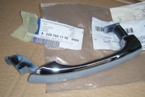
=== Parts === | |||
{| | {| | ||
|[[File:W220_door_handle_left_A2207601170_9999.jpg|thumb|none|Door handle (left) A2207601170 9999 (colorless - requires painting).]] | |[[File:W220_door_handle_left_A2207601170_9999.jpg|thumb|none|Door handle (left) A2207601170 9999 (colorless - requires painting).]] | ||
| Line 24: | Line 25: | ||
|} | |} | ||
=== KEYLESS-GO === | |||
==== Wiring ==== | |||
KEYLESS-GO handles have wiring with 4-pin connector. | |||
{| | {| | ||
|[[File:W220_keyless-go_door_handle_connector_door_side.jpg|thumb|none|KEYLESS-GO door handle connector (door side).]] | |[[File:W220_keyless-go_door_handle_connector_door_side.jpg|thumb|none|KEYLESS-GO door handle connector (door side)]] | ||
|[[File:W220_keyless-go_door_handle_connector_wires.jpg|thumb|none|KEYLESS-GO door handle connector (handle side)]] | |||
|[[File:W220_keyless-go_door_handle_connector.jpg|thumb|none|KEYLESS-GO door handle connector pins (handle side)]] | |||
|} | |||
* Pin 1 - white wire | |||
* Pin 2 - red wire | |||
* Pin 3 - blue wire | |||
* Pin 4 - yellow wire | |||
The white and red wires (pin 1 and 2) are used for capacitive sensor that signals when a hand is inserted into a door handle. | |||
The blue and yellow wires (pin 3 and 4) close circuit when the KEYLESS-GO button is pressed on a door handle. | |||
W215 vehicles have exactly the same door handles with the only difference that [[KEYLESS-GO]] handle has the opposite connector (male instead of female) . | |||
{| | |||
|[[File:W215_and_W220_door_handles_left_with_keyless-go.jpg|thumb|none|W215 vs W220 left door handle (note the opposite connectors).]] | |[[File:W215_and_W220_door_handles_left_with_keyless-go.jpg|thumb|none|W215 vs W220 left door handle (note the opposite connectors).]] | ||
|} | |} | ||
=== | ==== Button ==== | ||
It is common | It is common that by age the KEYLESS-GO button starts malfunction or fails completely. | ||
The correct working of KEYLESS-GO button (microswitch) can be tested by measuring the resistance between connector pins 3 and 4. When the microswitch is not pressed the resistance must be infinite. When pressed the circuit is closed resulting in < 500 Ohm resistance measurement. | The correct working of KEYLESS-GO button (microswitch) can be tested by measuring the resistance between connector pins 3 and 4. When the microswitch is not pressed the resistance must be infinite. When pressed the circuit is closed resulting in < 500 Ohm resistance measurement. | ||
{| | {| | ||
|{{#ev:youtube|https://www.youtube.com/watch?v=DAbFvn_emi8|320|left| | |[[File:W220_keyless-go_door_handle_test_multimeter.jpg|thumb|none|Testing KEYLESS-GO button using multimeter]] | ||
|{{#ev:youtube|https://www.youtube.com/watch?v=DAbFvn_emi8|320|left|Testing several KEYLESS-GO handles using multimeter|frame}} | |||
|} | |} | ||
==== | ==== Button rubber ==== | ||
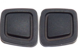
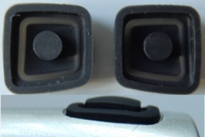
After years of wear the rubber on KEYLESS-GO button develops cracks and allows water to get in. | After years of wear the rubber on KEYLESS-GO button develops cracks and allows water to get in. The moisture in turn can lead to the damage of the button microswitch. | ||
Aftermarket replacement rubber buttons can be bought on ebay for EUR 40 per pair. The residues of the old rubber have to be removed and the new button glued on. | |||
If the KEYLESS-GO microswitch is also damaged, the easiest solution is to buy a used handle and repaint it. | |||
{| | {| | ||
| Line 55: | Line 73: | ||
|} | |} | ||
==== Capacitive sensor ==== | |||
It is common that by age the KEYLESS-GO capacitive sensor inside a handle starts to malfunction or fails completely. | |||
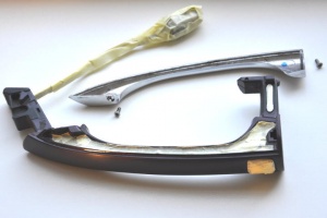
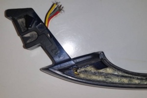
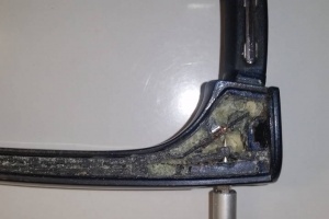
The inside of KEYLESS-GO door handle contains circuit board. The | The inside of a KEYLESS-GO door handle contains a circuit board. The space inside the handle is filled with epoxy. | ||
The microswitch of KEYLESS-GO button seems to be connected using a type of thin ribbon cable. | |||
{| | {| | ||
Revision as of 22:12, 15 May 2021
Handles
Parts
 |
 |
| Part No. | Notes |
|---|---|
| A2207601170 | Left (front/rear) |
| A2207601270 | Right (front/rear) |
| A2207601370 | Left (front/rear). For vehicles with option code 889 (KEYLESS-GO). |
| A2207601470 | Right (front/rear). For vehicles with option code 889 (KEYLESS-GO). |
KEYLESS-GO
Wiring
KEYLESS-GO handles have wiring with 4-pin connector.
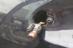 |
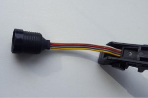 |
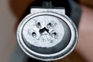 |
- Pin 1 - white wire
- Pin 2 - red wire
- Pin 3 - blue wire
- Pin 4 - yellow wire
The white and red wires (pin 1 and 2) are used for capacitive sensor that signals when a hand is inserted into a door handle. The blue and yellow wires (pin 3 and 4) close circuit when the KEYLESS-GO button is pressed on a door handle.
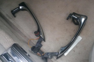
W215 vehicles have exactly the same door handles with the only difference that KEYLESS-GO handle has the opposite connector (male instead of female) .
 |
Button
It is common that by age the KEYLESS-GO button starts malfunction or fails completely.
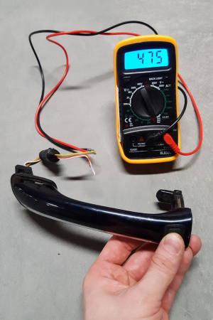
The correct working of KEYLESS-GO button (microswitch) can be tested by measuring the resistance between connector pins 3 and 4. When the microswitch is not pressed the resistance must be infinite. When pressed the circuit is closed resulting in < 500 Ohm resistance measurement.
 |
Button rubber
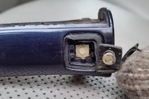
After years of wear the rubber on KEYLESS-GO button develops cracks and allows water to get in. The moisture in turn can lead to the damage of the button microswitch.
Aftermarket replacement rubber buttons can be bought on ebay for EUR 40 per pair. The residues of the old rubber have to be removed and the new button glued on.
If the KEYLESS-GO microswitch is also damaged, the easiest solution is to buy a used handle and repaint it.
 |
 |
 |
Capacitive sensor
It is common that by age the KEYLESS-GO capacitive sensor inside a handle starts to malfunction or fails completely.
The inside of a KEYLESS-GO door handle contains a circuit board. The space inside the handle is filled with epoxy.
The microswitch of KEYLESS-GO button seems to be connected using a type of thin ribbon cable.
 |
 |
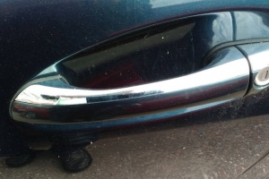
Chrome
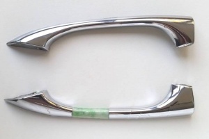
With time the chrome layer of door handle develops bubbles and starts to peal off.
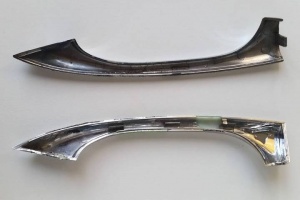
The chrome part is not sold separately, but can be replaced from another handle.
The chrome on KEYLESS-GO door handles can be easily removed by unscrewing two screws.
The chrome on the door handle without KEYLESS-GO button can be pulled off by carefully prying it off from the inner side of the door handle.
 |
 |
 |
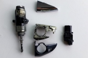
Driver's door lock
Door pillar panel covers
| Part No. | Notes |
|---|---|
| A2206900787 (~ EUR 50) | Front left |
| A2206900887 (~ EUR 50) | Front right |
| A2206901187 (~ EUR 50) | Rear left |
| A2206901287 (~ EUR 50) | Rear right |
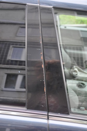
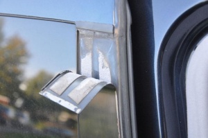
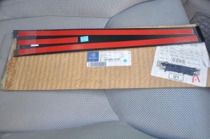
The covers are held in place by an extremely strong tape that is already on the replacement parts. One must thoroughly clean the old tape residue off, or it will interfere with a proper mount - it can hold the new part too far out. Care must be exercised in positioning the new parts.
 |
 |
 |
There are aftermarket carbon covers available on ebay, however, these covers come without plastic top ending.
Door Handle Latch Mechanism
Issues
- Inner handle is too loose and will not pull the latch mechanism far enough forward to release the latch.
- There is no tension adjustment for the cable.
- The cable slips out of the guide very easily as you move the inner door cover away from the door.
- A common fault is improper positioning of the cable in the inner handle mechanism.
Solution
At the back of the door handle mechanism there is a "Guide" - the inner part of the cable must be threaded into the guide (1 in the photo), and the cable jacket fitted into a small receptacle (at 2).
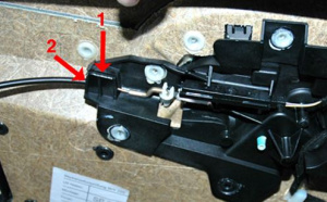
With that done, the cable is positioned properly, the tension is correct, the door handle operates the latch, and springs back to the proper position when released.