EVAP system: Difference between revisions
(updated info) |
|||
| Line 119: | Line 119: | ||
Check aeration at the activated charcoal canister for contamination | Check aeration at the activated charcoal canister for contamination | ||
(e.g. dust, spider's webs). | (e.g. dust, spider's webs). | ||
== Activated charcoal canister == | |||
<!-- | |||
GF47.30-P-3102F, Activated charcoal canister location/task/design/function, 15.5.98 | |||
MODEL 124 with ENGINE 104.942 /980 /992, 119.974 /975 | |||
MODEL 129 with ENGINE 104.943 /991 as of 1.8.96, 112.923 /943, 113.961, 119.982, 120.983 | |||
MODEL 140 with ENGINE 104.944 /994 as of 1.8.96, 119.981 /980, 120.982 | |||
MODEL 163 with ENGINE 112.942 /970, 113.942 /965 MODEL 168 with ENGINE 166.940 /960 /990 /995 | |||
MODEL 170 with ENGINE 111.946 as of 1.6.98, 111.943 /973 /958 /983, 112.947 | |||
MODEL 202 with ENGINE 104.941 as of 1.8.96, 111.921 as of 1.9.98, 111.974, 111.975 as of 1.8.96, 111.944 /945 /952 /956, 112.910 /920 | |||
MODEL 203 with ENGINE 111.951 /955, 112.912 /916 /946 /953 | |||
MODEL 208 with ENGINE 111.944 /945 /975 /956 /982, 112.940, 113.943 | |||
MODEL 209 with ENGINE 112.912 /955, 113.968 | |||
MODEL 210 with ENGINE 104.995, 111.942 as of 1.9.98, 111.947 /957, 112.911 /914 /921 /941, 113.940, 119.985 /980 | |||
MODEL 211 with ENGINE 112.913 /917 /949 /954, 113.967 /969 | |||
MODEL 215 with ENGINE 113.960, 137.970 | |||
MODEL 220 with ENGINE 112.922 /944 /972 /975, 113.941 /948 /960 /966, 137.970 | |||
MODEL 230 with ENGINE 112.973, 113.963 | |||
--> | |||
{| | |||
| | |||
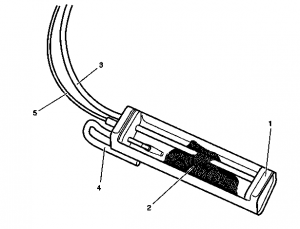
* 1 - Housing | |||
* 2 - Activated charcoal granulate | |||
* 3 - Vent line of the fuel tank | |||
* 4 - Vent line of the activated charcoal canister (USA with activated charcoal canister shutoff valve) | |||
* 5 - Purge line (to the purge control valve) | |||
|[[File:W220_activated_charcoal_canister.png|300px]] | |||
|} | |||
The task of the activated charcoal canister is ventilation and deventilation of the fuel tank and storing the fuel vapors temporarily for subsequent purging. | |||
The hausing of the activated charcoal canister is filled with activated charcoal granulate, divided into different chambers by intermediate walls in order to achieve optimal flow through the activated charcoal. | |||
USA with ORVR: Quantities of around 2.7 to 3.5 l. | |||
The fuel vapors released from the fuel tank (USA with ORVR or when refueling) are bonded | |||
to the activated charcoal. When purging is activated, they are drawn in by the engine | |||
and combusted. The activated charcoal is completely regenerated in the ideal case. | |||
The ventilation and deventilation of the fuel tank takes place over the activated charcoal canister. | |||
<!-- GF47.30-P-3102-01M, Activated charcoal canister position --> | |||
The activated charcoal canister is located at the rear in the rear left wheelhouse. | |||
{| | |||
| | |||
* 77 - Activated charcoal canister | |||
* A - Activated charcoal canister line to purge control valve | |||
* D - Activated charcoal canister line to fuel tank | |||
|[[File:W220_activated_charcoal_canister_location.jpg|400px]] | |||
|} | |||
{| | |||
| | |||
USA with ORVR: | |||
* 77 - Activated charcoal canister | |||
* Y58/4 - Activated charcoal canister shutoff valve | |||
|[[File:W220_activated_charcoal_canister_with_orvr_location.jpg|400px]] | |||
|} | |||
== Parts == | == Parts == | ||
Revision as of 07:42, 29 September 2021
The Evaporative Emission Control System (EVAP) is used to prevent gasoline vapors from escaping into the atmosphere from the fuel tank and fuel system at all times.
A typical system consists of the fuel tank, an EVAP vapor storage canister full of charcoal, valves, hoses and a sealed fuel tank gas cap. The EVAP system is designed to stop fuel system fumes from leaking directly into the atmosphere. Vent lines from the fuel tank pass vapors to the vapor canister, where they are trapped and stored until the engine is started. When the engine is warm and the vehicle is going down the road, the PCM then opens a purge valve allowing the vapors to be drawn from the storage canister into the intake manifold. The fuel vapors are then burned in the engine along with the air/fuel mixture.
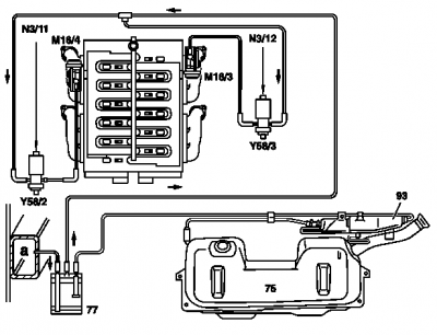
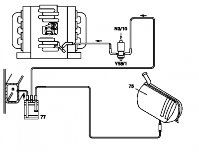
Fuel evaporation control system function
|
Shown on engine 119
|
|
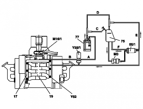
The fuel evaporation control system prevents fuel vapors escaping to atmosphere. This is done by storing the fuel vapors temporarily in the activated charcoal canister.
When the engine is running, the fuel vapors stored in the activated charcoal canister are drawn off through the purge control valve and combusted in the engine. The activated charcoal canister is purged (re-generated) at:
- Coolant temperature > 70 °C
- Blocking time after engine start elapsed, approx. 2 minutes
- Engine not in deceleration mode
The purge quantity is controlled by the ME-SFI control unit operating the purge control valve. The purge quantity is determined by constantly opening and closing the purge control valve for on and off periods of various lengths.
The idle speed control prevents changes in engine speed resulting from purging. A richer or leaner fuel-air mixture is produced in line with the charge of the activated charcoal canister with fuel vapors.
Air admission to fuel tank. Air is admitted through the activated charcoal canister. This is done through the activated charcoal canister, whereby air is drawn out of the vent/breather line or fuel vapors are drawn from the activated charcoal canister into the fuel tank.
Air release from fuel tank. The fuel tank is vented through the activated charcoal canister. The fuel vapors flow to the activated charcoal canister, where they are stored or drawn into the intake manifold in case of simultaneous regeneration.
Vent valve. On vehicles fitted with a vent valve the fuel tank is vented from a pressure of 30 to 50 mbar, and air admitted at a vacuum of 1 to 16 mbar. In addition, this prevents overfilling the fuel tank.
USA as of MY 98. During refueling the fuel vapors are collected at the filler neck and passed to the activated charcoal filter (ORVR = Onboard Refueling Vapor Recovery). Large activated charcoal canister.
Engines with charging (compressor or turbocharger). A check valve in the purge line prevents the boost pressure building up toward the activated charcoal canister.
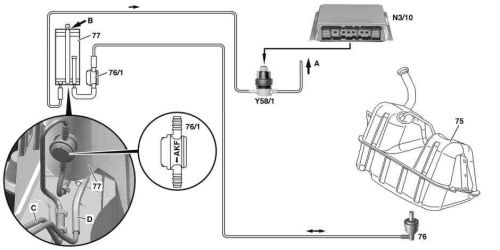
Model 215 from chassis no. A046659 (approx. 23.3.05), without USA and model 220 from chassis no. 469233 (ca. 23.3.05), without USA with ski bag (Code 282) or cooling compartment in rear backrest (Code 308) or with retrofitted additional vent valve (76/1):
The additional vent valve (76/1) prevents the vacuum from the intake manifold passing over the activated charcoal canister through to the fuel tank for enabled purging. For this purpose, the valve closes as soon as a membrane is pressurized with vacuum pressure from the activated charcoal canister. If excess pressure or vacuum pressure affects the other valve connection, it opens immediately. This means aeration/venting of the fuel tank is then possible in an unlimited fashion via the standard vent valve (76).
Pay attention to the installation position of the vent valve (76/1). Check aeration at the activated charcoal canister for contamination (e.g. dust, spider's webs).
Activated charcoal canister
The task of the activated charcoal canister is ventilation and deventilation of the fuel tank and storing the fuel vapors temporarily for subsequent purging.
The hausing of the activated charcoal canister is filled with activated charcoal granulate, divided into different chambers by intermediate walls in order to achieve optimal flow through the activated charcoal. USA with ORVR: Quantities of around 2.7 to 3.5 l.
The fuel vapors released from the fuel tank (USA with ORVR or when refueling) are bonded to the activated charcoal. When purging is activated, they are drawn in by the engine and combusted. The activated charcoal is completely regenerated in the ideal case. The ventilation and deventilation of the fuel tank takes place over the activated charcoal canister.
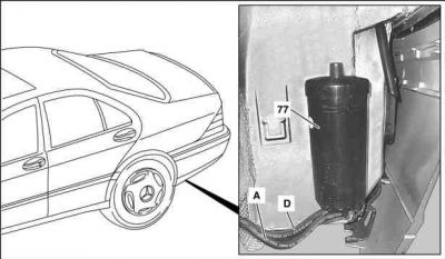
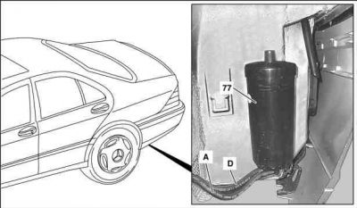
The activated charcoal canister is located at the rear in the rear left wheelhouse.
|
|
|
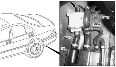
USA with ORVR:
|
|
Parts
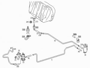
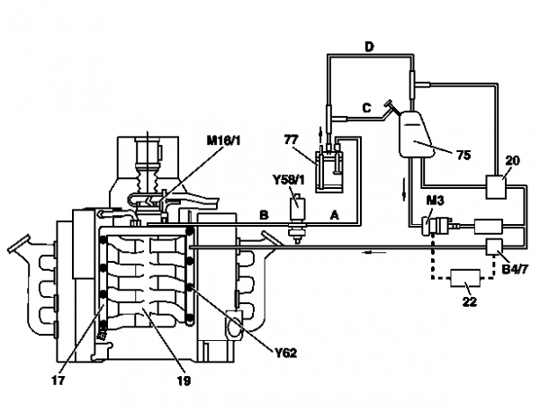
Connection diagram for evaporative emission control system (M113)
Connection diagram for evaporative emission control system (M112)
Remove/install activated charcoal canister
|
Shown on MODEL 220
|
|
- Raise vehicle.
- Remove rear left wheelhousing liner
- Detach activated charcoal canister - purge control valve line (A) and vent valve line - activated charcoal canister to fuel tank (D) at activated charcoal canister (77)
- Remove activated charcoal canister (77). Lift up and out.
- Install in the reverse order
