WIS 88.50 Trunk/Boot Lid: Difference between revisions
Ricebubbles (talk | contribs) |
(added components section) |
||
| Line 1: | Line 1: | ||
== Components == | |||
<!-- AR88.50-P-5020M --> | |||
{| | |||
|[[File:W220_trunk_lid_illustration.jpg]] | |||
| | |||
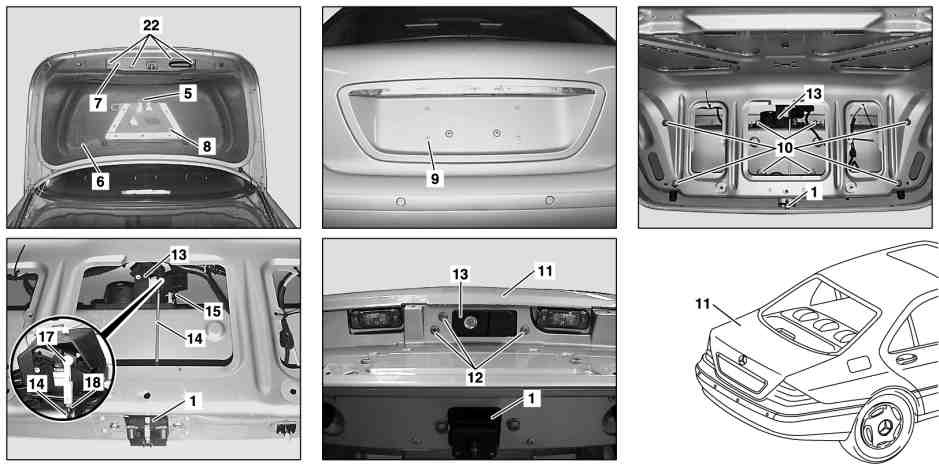
* 1 - Trunk lid lock | |||
* 5 - Bracket | |||
* 6 - Inner trunk lid paneling | |||
* 7 - Cover | |||
* 8 - Hazard warning triangle | |||
* 9 - Covering | |||
* 10 - Nuts | |||
* 11 - Trunk lid | |||
* 12 - Bolts | |||
* 13 - Trunk lid handle | |||
* 14 - Release rod | |||
* 15 - Electrical connector | |||
* 17 - Ball head | |||
* 18 - Nut | |||
* 22 - Bolts | |||
|} | |||
{| | |||
|[[File:W220_trunk_lid_illustration2.jpg]] | |||
| | |||
* 1 - Trunk lid lock | |||
* 2 - Locking eye | |||
* 3 - Bolts | |||
* 4 - Bolts | |||
* 14 - Release rod | |||
* 16 - Pneumatic line | |||
|} | |||
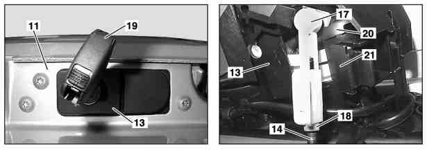
{| | |||
|[[File:W220_trunk_lid_illustration3.jpg]] | |||
| | |||
* 11 - Trunk lid | |||
* 13 - Trunk lid handle | |||
* 14 - Release rod | |||
* 17 - Ball head | |||
* 18 - Nut | |||
* 19 - Mechanical key | |||
* 20 - Lever | |||
* 21 - Stop | |||
|} | |||
==Description - Trunk/Boot Lid== | ==Description - Trunk/Boot Lid== | ||
The S-Class Trunk/Boot Lid is pneumatically controlled and can have some or all of the following functions depending on the configuration codes as detailed on the [[Data Card | Vehicle Data Card (List of Option Codes)]]. | The S-Class Trunk/Boot Lid is pneumatically controlled and can have some or all of the following functions depending on the configuration codes as detailed on the [[Data Card | Vehicle Data Card (List of Option Codes)]]. | ||
Revision as of 19:07, 14 February 2016
Components

|
|
|
|
Description - Trunk/Boot Lid
The S-Class Trunk/Boot Lid is pneumatically controlled and can have some or all of the following functions depending on the configuration codes as detailed on the Vehicle Data Card (List of Option Codes).
- Auto opening
- Auto or self closing
- Extension and retraction of Trunk/Boot Lid handle
- Pneumatically operated lock and unlock with mechanical (emergency key) overide
- Trunk/Boot Lid pull down function.
The positive and negative pressures required for the pneumatic control of the Trunk/Boot Lid functions are generated by the Pneumatic System Equipment (PSE) Pump.
Retractable Trunk Lid Grip (RTG) - Trunk/Boot Lid
Some M-B W220s have an extendable and retractable Trunk/Boot Lid handle called the Retractable Trunk Lid Grip (RTG) option. See also WIS 88.52 Retractable Trunk Lid Grip (RTG).
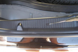
- Photo of a W220 2003 (Update) S500L with Retractable Trunk Lid Grip (RTG) in hidden or retracted position.
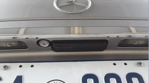
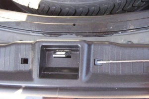
- Photo of a W220 2003 (Update) S500L with Retractable Trunk Lid Grip (RTG) in open or extracted position.
TBD (Will upload as soon as mine is working again!)
Remote Locking - Trunk/Boot Lid
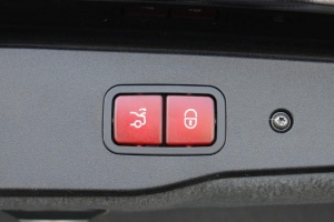
Some M-B W220s have a self closing and remote locking Trunk/Boot Lid. What this means exactly is TBD.
Part Numbers - Trunk/Boot Lid
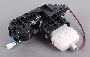
Locking Mechanism Actuator - Trunk/Boot Lid
- Locking Mechanism Actuator 220 750 0684
Issues - Trunk/Boot Lid
Common issues relating to the trunk/boot lid functions are;
- Hissing Sound on Trunk Closure
- Broken or Failed Pneumatic Actuators
- Cracked or broken pneumatic lines.
- Cannot remove the actuator rod to get the locking mechanism out of the trunk
- Open the Trunk/Boot when the Battery is Dead
How to Jump Start the Car and Open the Trunk/Boot when the Battery is Dead
Issue
A completely dead battery prevents the boot lid from being electrically opened. A jump start is not possible if you cannot access the battery as the W220 does not have accessible jump ports.
Solution
Extract the mechanical key from the Remote Key Fob and use it to open the Trunk. If that doesn't work you may have to charge the battery prior to jump starting the car.
- Pull the carpet back from the top under the front passenger side dash.
- Behind the Styrofoam insulation there is an aluminum plate.
- Unscrew the 3-4 bolts to get to the positive terminal.
- Hook up a charger and charge the battery as long as possible.
- After a while you should be able to start the car.
- If the trunk still will not open reset it by removing the 20A yellow fuse from under the rear right passenger seat fuse box.
- Leave it out for about 5 mins.
- Then put it back in and then try to open the Trunk.
- The Trunk should now open.
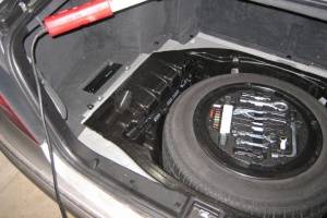
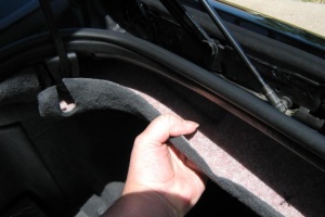
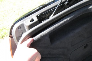
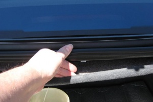
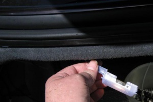
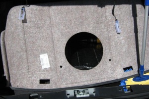
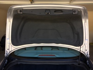
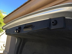
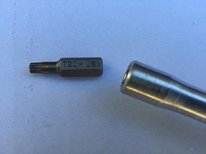
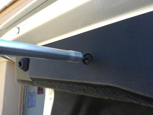
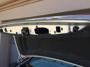
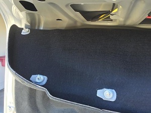
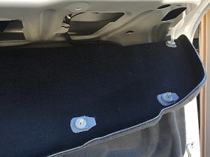
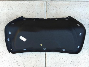
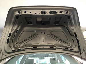
DIY - Removing Trunk Lid Lining
 |
 |
 |
 |
 |
 |
 |
 |
 |
DIY - Removing Trunk Lining
DIY - Repair of Broken Pneumatic Actuator 01
With thanks to BenzWorld member 'subscriber' for posting an excellent description of his repair of a broken locking mechanism pneumatic actuator.
Note the broken plastic tabs on the perimeter of the actuator.
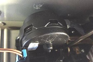
See http://www.benzworld.org/forums/w220-s-class/2532833-repair-part-220-750-0684-trunk.html
DIY - Repair of Broken Pneumatic Actuator 02
See WIS 88.52 Retractable Trunk Lid Grip (RTG) for a DIY repair of a broken actuator.
DIY - Repair of Pneumatic Actuator Pneumatic Solenoid Valves
Description - Pneumatic Actuator Pneumatic Solenoid Valves
In the Pneumatic Actuator there is a double solenoid valve which distributes the pneumatic pressure to the relevant actuator depending on the required result.
The exact description of which coil does what has yet to be determined and wasn't necessary for a thorough clean and bench test. It is something like the following: (Reference: HECK function on Pneumatic System Equipment (PSE) Pump.
- When the Boot/Trunk Lid is closed manually to the first position as identified by a loud click, the PSE HECK port provides +ve pressure (110KPa or 16psi) to the Boot/Trunk Lid Solenoid Valve Assembly and hence to the Large White Actuator which pulls the boot closed tightly, then the PSE HECK port changes to –ve pressure (19”Hg vacuum), which retracts the Handle (RTG), then returns the line to atmospheric pressure.
- When the Boot/Trunk Lid is commanded to open either by remote control on the key fob, by pressing the Boot/Trunk Lid button, or by pulling the internal Boot/Trunk Lid release button on the driver's door, the PSE HECK port provides +ve pressure (110KPa or 16psi) to the Boot/Trunk Lid Solenoid Valve Assembly and hence to the Small Black Actuator or "Hockey Puck" which opens the locking latch, thus releasing the lid which fully opens. +ve Pressure is also applied to the RTG Handle, which extends the Handle. After all this is finished the pneumatic line returns to atmospheric pressure.
DIY Clean and Regrease - Trunk Lid Actuator Pneumatic Solenoid Valves
Once the Boot/Trunk Lid Pneumatic Actuator is removed from the vehicle it can be dismantled on the work bench. See WIS 88.52 Retractable Trunk Lid Grip (RTG) for the removal method.
- Press in the two small plastic tabs and the Pneumatic Solenoid Valve Assembly can be with drawn.
- Remove the top front cover over the electrical connector.
- Then press in two small plastic tabs and remove the top rear cover.
Photo of disassembled Pneumatic Solenoid Valve Assembly
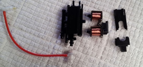
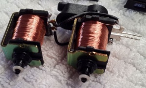
Closeup of coils and seals.
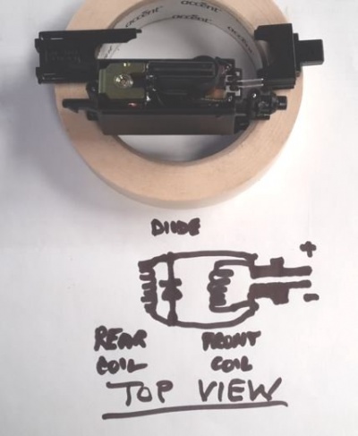
The electrical circuit diagram is very simple with the two coils just connected in parallel. A diode is also connected across the coils to reduce current surge when the coils are switched off. (Here is the theory: The magnetic energy stored in energised coils can generate a large spark across the operating switch when it is opened and consequently burn the electrical contacts in the switch. A diode provides a path for this excess energy to dissipate harmlessly.) The downside of having a diode in the circuit is that the electrical contacts are now polarised and correct polarity of any applied test voltage must be observed otherwise the diode will burn out. This just means that the '+' and '-' signs on the next diagram must be observed when applying a 12 Volt DC test voltage.
Circuit Diagram of Trunk Lid Actuator Pneumatic Solenoid Valves
- Reassemble in the reverse order but apply silicon dielectric or vacuum grease to the pneumatic seals before assembly.
