WIS 54.00 General: Difference between revisions
Jump to navigation
Jump to search
Ricebubbles (talk | contribs) (Moved CAN detail from WIS 82.90 On-board Communication System which was wrong.) |
Ricebubbles (talk | contribs) mNo edit summary |
||
| Line 1: | Line 1: | ||
==CAN (Controller Area Network)== | ==Description - CAN (Controller Area Network)== | ||
The | The CAN (Controller Area Network) Bus is a digital computer network which provides: | ||
* A digital communication link between multiple Electronic Control Modules (ECM). | * A digital communication link between multiple Electronic Control Modules (ECM). | ||
* Provides message specific addressing. | |||
* A two wire, bi-directional communication link with data transmitted according to priority. | * A two wire, bi-directional communication link with data transmitted according to priority. | ||
* The two wire (CAN H and CAN L) method ensures that any interference picked up in the wires is common to both CAN H and CAN L signals and is not "seen" by the receiving module. | |||
* The two wire (CAN H and CAN L) method ensures that any interference picked up in the wires is common to both CAN H and CAN L signals and is not "seen" by the receiving module. | |||
The W220 has two separate CAN (Controller Area Network) Bus systems. | |||
* CAN C - Engine CAN (also known as Chassis CAN) which has fast communication speeds of 125 kbps or 500 kbps. | |||
* CAN B - Interior CAN (also known as Body CAN) which has communication speeds of 83 kbps. | |||
===Example | ===Example - W220 CAN B Network=== | ||
The CAN B or Interior CAN is also known as Body CAN. | The CAN B or Interior CAN is also known as Body CAN. | ||
[[File:Example_of_W220_CAN_B.JPG|500px|center]] | |||
==Issues - CAN (Controller Area Network)== | |||
* If one wire becomes faulty the CAN signal should still get through. | |||
* If both CAN H and CAN L signals are faulty no communication is possible. | |||
==Diagnosing - CAN (Controller Area Network)== | |||
Using the [[STAR Diagnosis System (SDS) or Diagnosis Assistance System (DAS)|STAR DAS]] is the best method to diagnose CAN function. | |||
Alternatively, for simple analysis, CAN Signal Levels can be measured using an oscilloscope with respect to 0V or Ground or differentially between CAN H and CAN L at any CAN Bus Connector. | |||
'''Warning! Be careful of causing electrostatic damage to electronic components.''' | |||
=== | ===Typical Connector - CAN (Controller Area Network)=== | ||
(Note wire pairs) | |||
[[File:Typical_W220_CAN_Bus_Connector.JPG|300px|center]] | |||
===Typical | ===Typical Signal Levels - CAN (Controller Area Network)=== | ||
* CAN H (High) steady 0.025V when the CAN Bus is dormant (not communicating) and, | * CAN H (High) steady 0.025V when the CAN Bus is dormant (not communicating) and, | ||
* CAN H (High) 0.65V amplitude when the CAN Bus is communicating. | * CAN H (High) 0.65V amplitude when the CAN Bus is communicating. | ||
Revision as of 11:47, 19 March 2015
Description - CAN (Controller Area Network)
The CAN (Controller Area Network) Bus is a digital computer network which provides:
- A digital communication link between multiple Electronic Control Modules (ECM).
- Provides message specific addressing.
- A two wire, bi-directional communication link with data transmitted according to priority.
- The two wire (CAN H and CAN L) method ensures that any interference picked up in the wires is common to both CAN H and CAN L signals and is not "seen" by the receiving module.
The W220 has two separate CAN (Controller Area Network) Bus systems.
- CAN C - Engine CAN (also known as Chassis CAN) which has fast communication speeds of 125 kbps or 500 kbps.
- CAN B - Interior CAN (also known as Body CAN) which has communication speeds of 83 kbps.
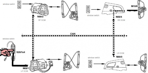
Example - W220 CAN B Network
The CAN B or Interior CAN is also known as Body CAN.

Issues - CAN (Controller Area Network)
- If one wire becomes faulty the CAN signal should still get through.
- If both CAN H and CAN L signals are faulty no communication is possible.
Diagnosing - CAN (Controller Area Network)
Using the STAR DAS is the best method to diagnose CAN function.
Alternatively, for simple analysis, CAN Signal Levels can be measured using an oscilloscope with respect to 0V or Ground or differentially between CAN H and CAN L at any CAN Bus Connector.
Warning! Be careful of causing electrostatic damage to electronic components.
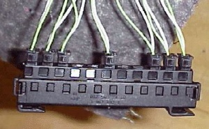
Typical Connector - CAN (Controller Area Network)
(Note wire pairs)

Typical Signal Levels - CAN (Controller Area Network)
- CAN H (High) steady 0.025V when the CAN Bus is dormant (not communicating) and,
- CAN H (High) 0.65V amplitude when the CAN Bus is communicating.
- Signal data for CAN H is a voltage level going high.
- CAN L (Low) steady 11V when the CAN Bus is dormant (not communicating) and,
- CAN L (Low) 4.65V amplitude when the CAN Bus is communicating.
- Signal data for CAN L is a voltage level going low.