Exhaust gas recirculation (EGR): Difference between revisions
| Line 74: | Line 74: | ||
* 89/5 - Housing | * 89/5 - Housing | ||
|} | |} | ||
== Position == | |||
<!-- GF14.20-P-3106-01A --> | |||
The EGR [ARF] vacuum transducer is mounted behind the right cylinder head. | |||
{| | |||
|[[File:W220_Exhaust_gas_recirculation_vacuum_transducer_position.png]] | |||
| | |||
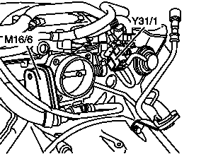
* M16/6 - Throttle valve actuator | |||
* Y31/1 - EGR vacuum transducer | |||
|} | |||
== Function == | |||
<!-- GF14.20-P-3106-02A --> | |||
<!-- GF14.20-P-3106A --> | |||
{| | |||
|[[File:W220_Exhaust_gas_recirculation_vacuum_transducer_function.png]] | |||
| | |||
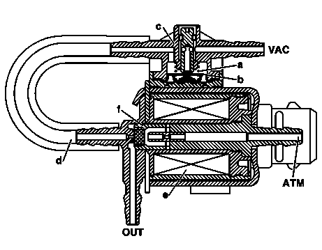
* A - Compression spring | |||
* B - Valve plate with diaphragm | |||
* c - Housing, pressure regulator | |||
* D - Hose line (guides controlled vacuum of approx. -200 mbar to the electrical unit) | |||
* e - Coil | |||
* F - Electromagnetically operated valve unit | |||
* ATM - Atmospheric pressure, air admission via cylinder head | |||
* OUT - Controlled vacuum to EGR valve | |||
* VAC - Vacuum supply from intake manifold | |||
|} | |||
From connection VAC the intake manifold vacuum reaches the | |||
pressure regulator, which stabilizes the intake manifold vacuum in | |||
line with engine speed and throttle valve position via a control | |||
valve to approx. -200 mbar. | |||
The controlled vacuum flows further via a hose line to the following | |||
electric unit. | |||
This unit is actuated by the ME control unit with a pulse width | |||
modulation signal (frequency approx. 10 Hz, on/off ratio approx. 30 | |||
to 100%) at the ground end. The developing magnetic field | |||
influences via the coil anchor the valve unit as follows: | |||
* No signal from control unit: The connections OUT and ATM are linked. The exhaust gas recirculation valve is close (ventilated). | |||
* Signal from control unit: The valve unit opens proportional to the current flow in the coil. The vacuum acts partially or fully at connection OUT and operates the ERF valve accordingly. | |||
== Removing exhaust gas recirculation valve == | == Removing exhaust gas recirculation valve == | ||
Revision as of 19:03, 10 December 2016
Exhaust Gas Recirculation (EGR)
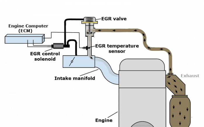
The Exhaust Gas Recirculation (EGR) system redirects a small portion of exhaust gases from the exhaust manifold back into the intake manifold (see the diagram) to lower the combustion temperature. The engine computer regulates the flow of the EGR gases by opening or closing the EGR valve. The EGR flow is at its maximum during steady highway cruising. The engine computer periodically tests the operation of the EGR system. If the engine computer detects that the EGR flow is less or greater than expected, it sets the fault code P0400 - Exhaust Gas Recirculation Flow Malfunction.
Function
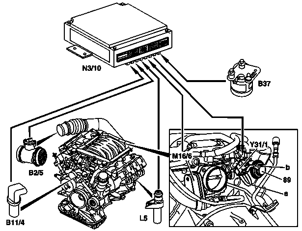
The exhaust gas recirculation valve (89) is combined with an electrical EGR pressure transducer (Y31/1).
The EGR pressure transducer (Y31/1) stabilizes the sharp vacuum fluctuations in the intake, and is actuated by the ME-SFI control unit with a PWM signal, which has a frequency of about 10 Hz and a duty cycle of about 30 to 100%.
The EGR valve is actuated with a vacuum of about 80 to 200 mbar, and is opened to varying widths in order to control the quantity of exhaust gases that are recirculated.
The exhaust gases are recirculated in line with the map stored in the ME control unit as soon as the following conditions are met:
- Coolant temperature between 60°C and 110°C
- Engine speed <3500 rpm
- Partial load.
The performance map is designed to optimize fuel consumption. In this case as much exhaust gas as possible is recirculated without impairing engine running or exhaust emissions.
Exhaust gas low in oxygen content is drawn in through the exhaust gas recirculation valve, depending on the cross-section of the valve opening. Consequently, the fuel-air mixture has a lower oxygen concentration. The combustion temperature drops and the formation of NOX is reduced.
The inducted air mass is reduced by the quantity of exhaust gases recycled. In line with this, the ME-SFI [ME] control unit meters less fuel.

|
|
Position
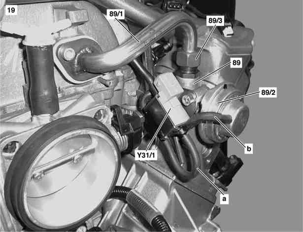
The EGR [ARF] vacuum transducer is mounted behind the right cylinder head.
|
|
Function
From connection VAC the intake manifold vacuum reaches the pressure regulator, which stabilizes the intake manifold vacuum in line with engine speed and throttle valve position via a control valve to approx. -200 mbar. The controlled vacuum flows further via a hose line to the following electric unit. This unit is actuated by the ME control unit with a pulse width modulation signal (frequency approx. 10 Hz, on/off ratio approx. 30 to 100%) at the ground end. The developing magnetic field influences via the coil anchor the valve unit as follows:
- No signal from control unit: The connections OUT and ATM are linked. The exhaust gas recirculation valve is close (ventilated).
- Signal from control unit: The valve unit opens proportional to the current flow in the coil. The vacuum acts partially or fully at connection OUT and operates the ERF valve accordingly.
Removing exhaust gas recirculation valve
|
|
|
- Remove cover on front side of engine
- Remove air filter housing
- Remove engine cover with integrated air filter
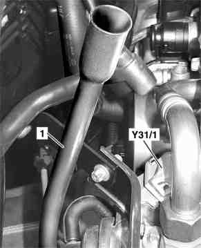
- Unplug connector on EGR pressure transducer (Y31/1).
- Detach vacuum line (b) to vacuum unit (89/2) and EGR pressure transducer (Y31/1)
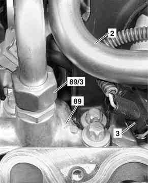
- Unscrew union nut (89/3) on exhaust gas recirculation valve (89)
- Dismount EGR line (89/1) from intake manifold (19)
- Unscrew exhaust gas recirculation pipe (89) from cylinder head
- Remove exhaust gas recirculation valve (89). Installation: Replace gaskets. Note length and routing of vacuum line from intake manifold to EGR [ARF] vacuum transducer (Y31/1). Incorrect routing may cause throttle lever to jam.
- Install in the reverse order
Fault codes
P0400 Exhaust Gas Recirculation Flow Malfunction
