Glove compartment: Difference between revisions
Jump to navigation
Jump to search
(→Removing and installing key block on glove compartment lid: replaced "lock cylinder" with "key block") |
|||
| Line 33: | Line 33: | ||
|} | |} | ||
==Removing and installing | ==Removing and installing key block on glove compartment lid== | ||
<!-- AR68.10-P-1250M, MODEL 215, 220, Removing and installing lock cylinder on glove compartment lid, 20.2.98 --> | <!-- AR68.10-P-1250M, MODEL 215, 220, Removing and installing lock cylinder on glove compartment lid, 20.2.98 --> | ||
| Line 39: | Line 39: | ||
|[[File:W220_removing_and_installing_lock_cylinder_on_glove_compartment_lid.jpg]] | |[[File:W220_removing_and_installing_lock_cylinder_on_glove_compartment_lid.jpg]] | ||
| | | | ||
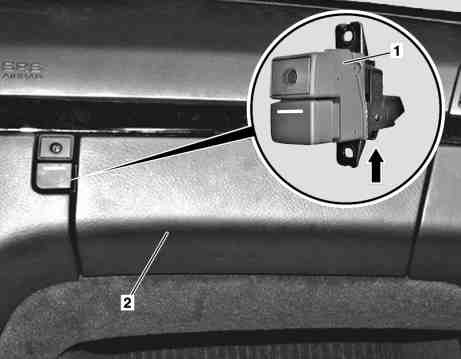
* 1 - | * 1 - Key block | ||
* 2 - Glove compartment | * 2 - Glove compartment | ||
|} | |} | ||
# Remove glove compartment | # Remove glove compartment | ||
# Unscrew mounting screws for | # Unscrew mounting screws for key block (1). Key block (1) is screwed onto instrument panel (2) from rear (two Torx 20 screws). | ||
# Remove | # Remove key block (1) to side | ||
# Unhook control cable from eye (arrow) on | # Unhook control cable from eye (arrow) on key block (1). Installation: Check function of control cable, adjust with knurled nut if necessary. | ||
# Install in opposite order | # Install in opposite order | ||
Revision as of 16:42, 17 April 2017
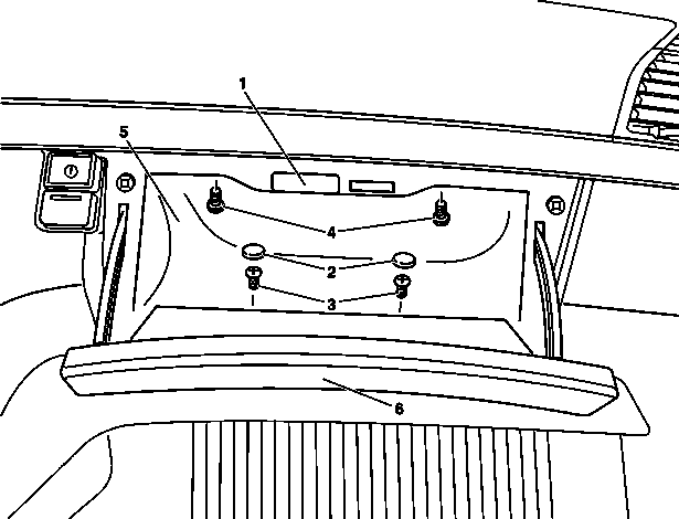
Removing and installing glove compartment
|
|
|
|
- Open glove compartment lid (6)
- Unclip glove compartment lamp (1) and disconnect connector
- Remove plugs (2)
- Unscrew screws (3)
- Unscrew screws (4)
- Pull glove compartment (5) completely out of instrument panel
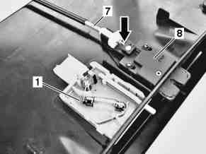
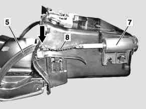
- Unhook control cable (7) on lock (8) on glove compartment (5). When unhooking the control cable (7) ensure that the slider (arrow) is not pulled out of the lock (8).
- Install in opposite order
Removing and installing key block on glove compartment lid
|
|
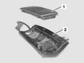
- Remove glove compartment
- Unscrew mounting screws for key block (1). Key block (1) is screwed onto instrument panel (2) from rear (two Torx 20 screws).
- Remove key block (1) to side
- Unhook control cable from eye (arrow) on key block (1). Installation: Check function of control cable, adjust with knurled nut if necessary.
- Install in opposite order
Removing and installing glove compartment lid
|
|
|
|
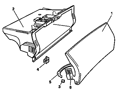
- Remove glove compartment (2)
- Unclip damping strip (8) on right from strap (5), (arrow) on glove compartment lid (1)
- Remove rubber stops (3) from strap (5)
- Pull expanding anchor (4) out of glove compartment (2). Pull expanding anchor out of glove compartment from inside.
- Remove glove compartment lid (1) together with hinges (6) uniformly downward
- Install in opposite order
- Adjust glove compartment lid
Disassembling and reassembling glove compartment lid
|
|
Adjusting glove compartment lid
|
|
|
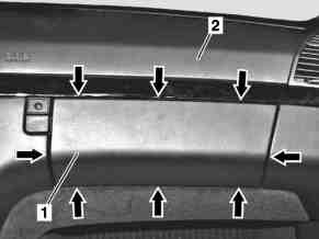
During entire operation pay attention to uniform transition and gap all the way around (arrows) on the glove compartment lid (1) in relation to the instrument panel (2).
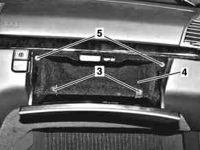
- Pull out both expanding anchors (3) from glove compartment lid (4) with small screwdriver
- Close glove compartment lid (1), adjust horizontal gap and transitions (arrows). Glove compartment lid (1) can be adjusted increment for increment on the hinge.
- Carefully open glove compartment lid (1) and press in expanding anchors (3)
- Check gap width at side, adjust.
- Differences in the gap width can be corrected slightly by loosening the mounting screws (4 each) for the glove compartment (4) and then moving.
- Check transition from glove compartment lid (1) to instrument panel (2), adjust. Adjustment is possible by screwing the two stop screws (5) in or out.
- Check for easy motion and proper function
 |
 |
 |
 |
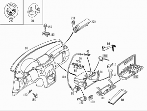
Parts
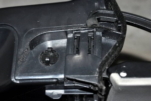
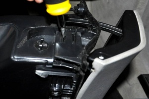
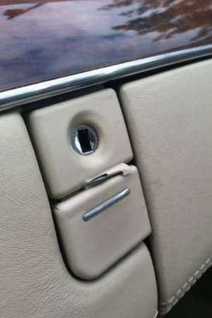
Worn glove box release button
Very popular issue is worn glove box release button. The color layer after years peals off leaving the plastic cap visible.
 |
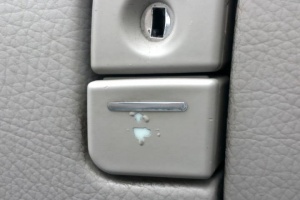 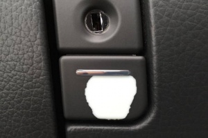 |
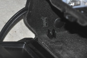
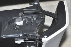
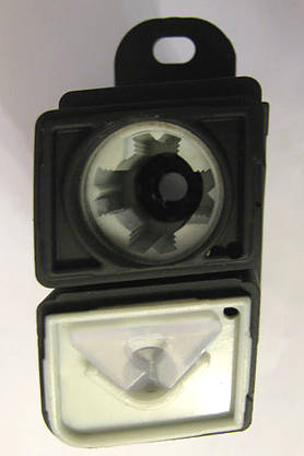
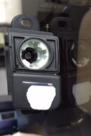
Worn cap on the key block can be replaced by ordering the cap (part number A2206890330 + color code) for around EUR 6.
To replace worn release button cap the whole lock cylinder has to be replaced (part number A2206800784 + color code) for around EUR 100. The lock mechanism must be removed and transferred to the new part.
 |
 |