Fanfare horns
Fanfare horns, function
Function requirements
- Circuit 15: ON
Function:
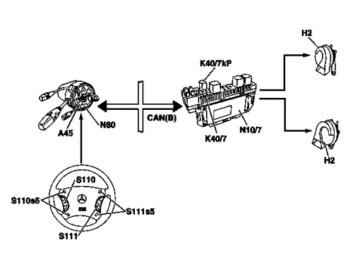
- When the impact absorber on the multifunction steering wheel is pressed, one or more buttons for the fanfare horns (S110s5, S111s5) are actuated.
- The status of these buttons is read in by the steering column module (N80).
- The steering column module (N80) sends a corresponding message on the (interior) CAN.
- This message is received by the right front SAM control unit (N10/7).
- The right front SAM control unit (N10/7) actuates the relay for the fanfare horns (K40/7kP). This relay is located on the right front fuse and relay module (K40/7).
- The relay for the fanfare horns (K40/7kP) connects the two fanfare horns (H2) to circuit 30.
- The signal sounds as soon as at least one of the buttons (S110s5, S111s5) is actuated.
Actuation of the fanfare horns (H2): One line of the fanfare horns (H2) is always connected to ground, actuation is therefore accomplished by connecting to circuit 30 (via K40/7kP).
Control of the relay for the fanfare horns (K40/7kP): The relay coil for the fanfare horns (K40/7kP) is permanently connected to circuit 15; when the fanfare horns (H2) are actuated, the other connection is connected to ground via the right front SAM control unit (N10/7).
Buttons for the fanfare horns (S110s5, S111s5): Four buttons for the fanfare horns are located on a circuit board below the impact absorber of the multifunction steering wheel. This ensures that the fanfare horns can be actuated from any point on the impact absorber. The two right and the two left buttons are each connected in parallel. They are read in voltage-coded by the steering column module (N80) together with the buttons of the left and right multifunction steering wheel button groups (S110, S111). See also applicable wiring diagrams.
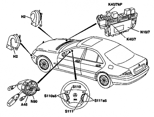
Fanfare horns arrangement of components
Fanfare horns interlinking of components
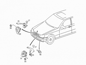
Parts


