WIS 35.30 Final Drive, Rear Drive Shafts
Description - WIS 35.30 Final Drive, Rear Drive Shafts
The rear wheel carrier and bearing assembly was changed on the W220 with the introduction of the update model, 2003 onward.
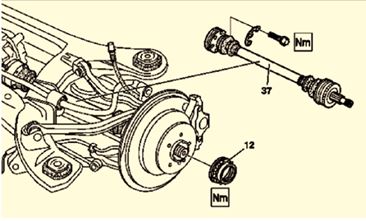
- The update W220 (2003 onward) has Plugin Rear Axle Shafts (No Inner Flange at Differential).
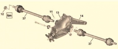
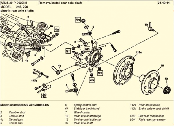
- W220 (1999 – 2003) has Screwed Rear Axle Shafts (Has Inner Flange at Differential).
Issues - Final Drive, Rear Drive Shafts
- The wheel bearings eventually become noisy and rough and need replacing.
DIY Replacement - Rear Wheel Bearings
Relevance
This document is relevant to my 2003 (Update) W220 S500L (Long Wheel Base Sedan) Chassis Number: 220.175, Engine Number: 113.960, Transmission: 9-speed (722.901) (7 forward and 2 reverse gears).
The referenced videos refer to a BMW 5 Series. They were a very good guide as to what was required in general terms to replace rear wheel bearings on a Mercedes-Benz W220.
However Be Warned! DIY replacement of rear wheel bearings in an Update 2003 W220 is NOT as straight forward as the video shows.
Reference WIS, W220’s have two styles of rear axle shafts. (See Section Rear Wheel Carrier and Bearing Assembly.) Early models have an inner flange on the differential onto which the rear axle shafts bolt. The referenced BMW videos are more compatible with this style of rear axle shaft. My update W220 has a newer style rear axle shaft without a flange plate. Consequently it is not possible to remove the rear axle shafts without some major dismantling. Fortunately this is not required to replace the rear wheel bearings. However the rear wheel carriers must be removed.
This article outlines how to remove the rear wheel carriers, leaving the rear axle shafts still connected to the differential.
References
- Removing Old Bearing: http://www.youtube.com/watch?v=wKYL9_4mXRI#t=48
- Installing New Bearing: http://www.youtube.com/watch?v=DX9iCZIVgFY
- WIS Document: ar35.20-p-0115i “Remove/install wheel carrier”
Acknowledgement
Thanks to BenzWorld Member cudaized.
Method for Removing Old Bearing
- Place car on secure jack stands and remove both rear wheels.
- Open Indent Catch for Rear Axle Collar Nut.
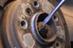
- Soak Axle Thread With Penetrene.
- While you are at it soak every likely bolt and nut that needs removing with Penetrene.
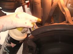
- Prevent Disk From Rotating
On the BMW in the referenced video an Allan Key was jammed against the brake calliper. On M-B W220 apply the parking brake.
- Undo Rear Wheel Axle Collar Nut (32mm 12 point socket) with a large breaker bar. This requires a huge amount of effort as the nut is torqued to 350Nm.
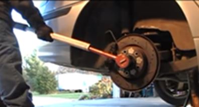
- Release Parking Brake
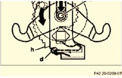
- Relax Parking Brake Cable Automatic Tensioning Mechanism. It took me several attempts to get this right. The trick is to rotate the detent eccentric bolt (g) counter clockwise when viewed from underneath until it clicks into place into the hold down clip spring (d).

- Unplug Brake Wear Sensor. My W220 has the rear brake wear sensor on the rear right side wheel only.
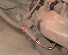
- Remove Brake Wear Sensor Bracket.
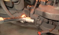
- Remove Rear Wheel Speed Sensor.
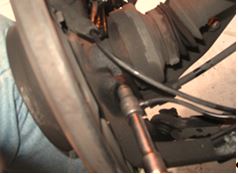
- Undo Nut on Tie Rod Ball Joint.
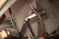
- Protect Brake Wear and Wheel Speed Sensors. Ensure brake wear and wheel speed sensors are placed out of the way so that they do not get damaged.
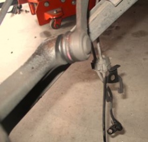
- Protect Tie Rod Ball Joint Rubber Boot. Prise back the rubber boot on the tie rod ball joint to expose the inner cone to avoid damaging the rubber boot with the ball joint separator.
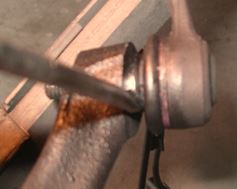
- Use Ball Joint Separator to Remove Tie Rod Ball Joint. Be warned the tie rod ball joint can release with a loud bang. It is a good idea to gently tap around the tie rod ball joint socket with a small hammer while it is under increasing tension.
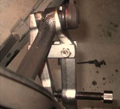
- Protect the Ball Joint Thread. Screwing a nut onto the ball joint thread protects the thread and also prevents the ball joint from flying apart. Ensure the nut is flush with the end of the thread for protection of the thread.
Also avoid damaging the rubber boot with the ball joint separator forked tongue.
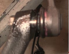
- Remove Brake Calliper Bolts. Use a 16mm ring or combination spanner on the brake calliper bolts.
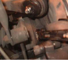
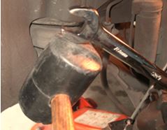
- I tap the end of the combination spanner with a rubber mallet to start the bolt undoing.
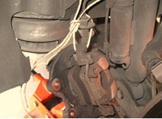
- Remove Brake Calliper. Suspend the brake calliper with wire so that the brake hose is not crimped or damaged.
- Release Automatic Parking Brake Mechanism.
- Adjust the parking brake shoes to provide maximum clearance. For access to the parking brake thumbwheel (ratchet mechanism) rotate the right side wheel so that the access hole (any wheel bolt hole) is positioned at 11:00 o’clock position. (For the left side wheel the access hole (wheel bolt hole) is positioned at the 1:00 o’clock position. Note also the correct angle for the wide bladed screw driver tip.
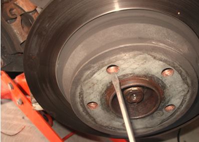
- Internal View of Parking Brake Thumbwheel. This is what you are trying to do. Rotate the parking brake thumbwheel (ratchet mechanism) downwards (screw driver handle upwards) to release the brake to its maximum clearance.
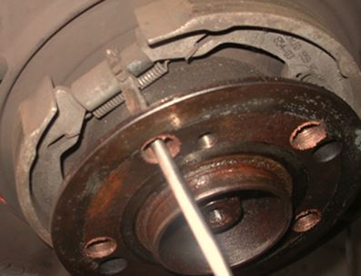
- Remove Brake Disk. Remove the Torx screw holding brake disk to rear axle shaft flange.
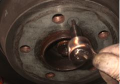
- If you haven’t previously used anti-seize grease on the hub you may have to tap the disc with a rubber mallet.
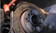
- Remove the Parking Brake Lower Retracting Spring. This requires a fair bit of effort but it is possible with normal 45º long nose pliers.
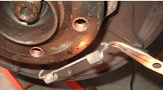
- Remove the Brake Shoe Retaining Springs. Remove the two rear brake shoe retaining springs by pushing them inwards and twisting 90º.
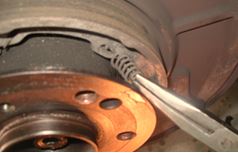
- Note the Retaining Springs Alignment for Re-installation. The installed position of the retaining springs is such that the hook end is facing radially inwards and pointing directly at the centre of the wheel hub.
- Remove the Parking Brake Shoes and Adjusting Mechanism over the Wheel Hub.
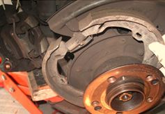
- Note the Orientation of the Parking Brake Adjusting Thumbwheel. The thrust piece (shorter length) is towards the front of the vehicle on both sides. This is the right side wheel.
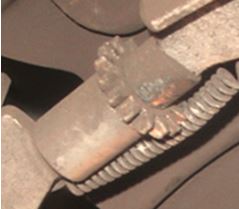
- The diagram in WIS shows the left side wheel with the thrust piece (c) (shorter length) on the left facing towards the front of the vehicle.
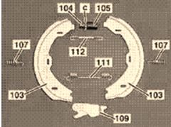
- Store the Parking Brake. Store the parking brake out of the way maintaining the correct positioning for each component to aid in re-installation.
- Remove the Parking Brake Expansion Lock. Carefully remove the parking brake expansion lock (actuating mechanism) and note the orientation. The hooked end of the Expansion Lock (109) is towards the front of the vehicle on both sides. This is the right side wheel.
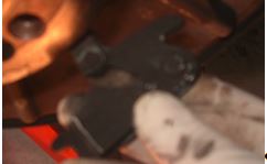
- WIS shows the left side wheel.

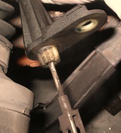
- Remove the Parking Brake Cable. Remove the bolt and withdraw the parking brake cable and place out of the way.
- Completely Remove Axle Collar Nut
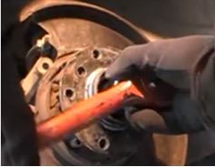
- Prepare to Remove Outer Axle Shaft Flange. Ensure that rear axle shaft spline is loose in the outer axle shaft flange before doing any more steps. If it is not loose, use an appropriate bearing puller to apply pressure to the axle shaft spline (place the nut back on and do it up flush with the end to protect the thread). Once the axle shaft is free it will move longitudinally several cms.
Install a bearing separator tool for two or three wheel lug bolts to push against. A splitter/separator tool is available on line for less than $70.
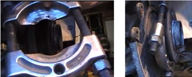
- I used my hydraulic jack to raise the rear wheel carrier so that the axle shaft was horizontal. Tighten two or three wheel lug bolts evenly to remove the outer axle shaft flange. Tap the axle shaft flange with a hard rubber mallet to assist breaking the joint. Be warned, it may release with a loud bang.
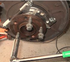
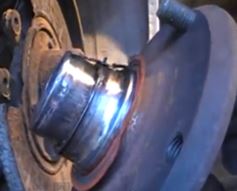
- Remove Rear Axle Shaft Flange. On my W220 I did not remove the rear axle shaft flange completely at this stage. It still had about 50% remaining which I pressed out after complete removal of the wheel carrier.
Note the bearing has separated into several pieces and the outer shell is firmly attached to the rear axle shaft flange. This image is from the BMW video and shows the bearing red seal which has also separated.
- Remove all the Wheel Carrier Linkages, Struts and Arms.
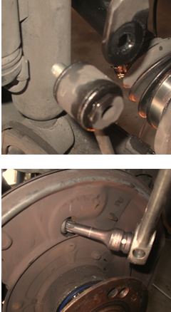
- As I dismantle items, I either reinsert the bolts and nuts or tape them to the relevant components ready for re-installation. This ensures that I use the correct parts and get the correct orientation.
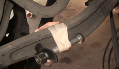
- Eventually the whole wheel carrier can be removed.
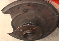
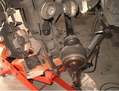
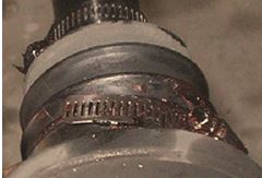
- Note also I have undone the inner and outer rubber boots on both rear axle shafts and re-greased the constant velocity joints. I used hose clamps with RTV Silicon sealer on re-installation and copper anti-seize grease which I use on just about everything.
- Complete Removal of Wheel Flange from Wheel Carrier. Now completely remove the wheel flange from the wheel carrier. Place the bearing separator around the rear axle flange and support it in an hydraulic press.
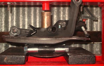
- Use a spacer with a diameter matching the axle flange diameter and press the axle flange out of the bearing. It doesn’t matter if the bearing is damaged as it is being replaced anyway.
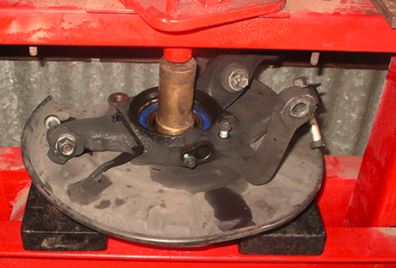
- Note the bearing has separated into two pieces and one of the outer shells is firmly attached to the rear axle shaft flange.
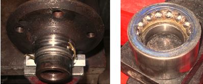
- Remove the Outer Bearing Shell. Carefully grind a channel through the bearing shell on the rear axle shaft flange. Be careful not to damage the surface of the rear axle shaft flange. It is not necessary to grind all the way through as the grinding process heats the bearing shell and expands it. Once only a small thickness remains, the bearing shell usually pops open on its own.
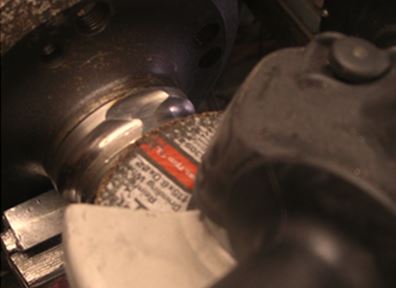
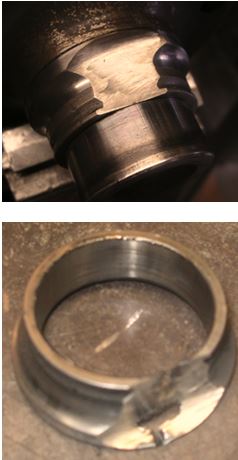
- Remove the Brake Dust Shield
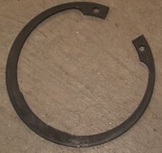
- Remove Bearing Snap Ring (Cir-Clip). Before the bearing can be removed, the securing cir-clip must be removed from the rear wheel carrier. This turned out to be more of a challenge than I envisaged. My cir-clip pliers would not budge the cir-clip. On the W220 it is a substantial piece of metal and is about 2mm thick.
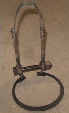
- I fashioned a cir-clip retractor out of some scrap nuts and bolts and was able to remove and reinsert the cir-clip in a very controlled fashion.
- Remove Rear Wheel Bearing. Press out the rear wheel bearing. I used a short length of 100mm bore casing as a spacer to support the wheel carrier.
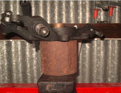
- A large washer was used to transfer the force from the press to the outer diameter of the bearing. The bearing pressed out very easily.
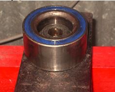
- Wheel Carrier Disassembled. There was a slight amount of bruising on the outer edges of the wheel carrier but nothing on any critical surface. The damage was easily cleaned up with a file.
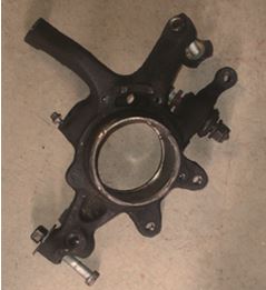
Method For Installing New Bearing
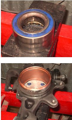
- New Rear Wheel Bearing.
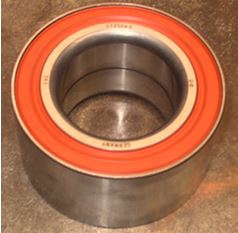
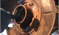
- Apply Anti-Seize to Bearing Housing.
- Prepare Installation Tools. I used a ¾” plumbing flange as the bearing support washer. It was placed on the press with the old bearing acting as a spacer for additional clearance. Use a large washer matching the diameter of the bearing to press the new bearing fully into place. It is important to use the correct diameter spacers so that the force of the press is mostly applied to the outer shell of the bearing.
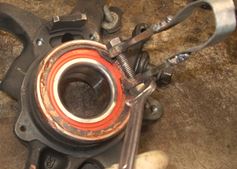
- Reinstall the Cir-Clip.
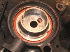
- Reinstall the Brake Dust Shield.
- Reinstall the Wheel Flange into the Wheel Carrier. This time it is important that the force of the press is applied to the inner bearing race. I fashioned a heavy duty washer of the correct diameter and used the old bearing race as a spacer to support the wheel carrier in the press. The ¾” plumbing flange and the old bearing provided the sufficient clearance.
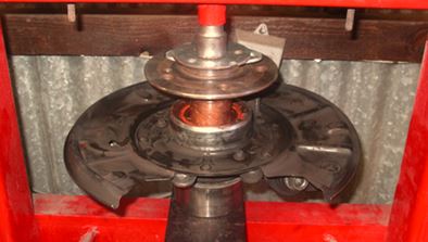
- Rear Axle Shaft Flange Reinstalled in Wheel Carrier. The rear axle shaft flange surface is flush with the internal bearing surface.
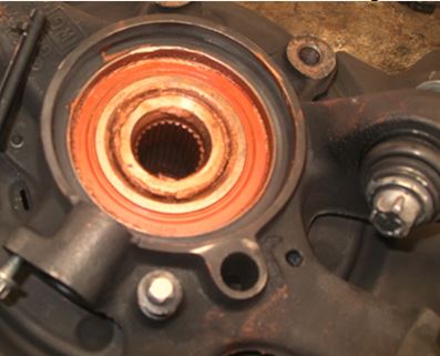
An Alternative Method for Installing New Bearing
- See referenced BMW video. If no hydraulic press is available use a large plumber’s flange plate with several large washers, a puller, nut and bolt (thread size 5/8” UNF).
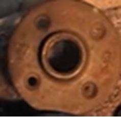
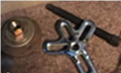
- Place Flange, Washers and Nut at back of Bearing Housing.
- Install Puller at Front of Bearing Housing.
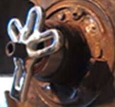
- Screw In New Bearing Until Puller Meets Housing.
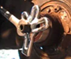
- Use Mallet to Ensure Even Pressure on Bearing (No Cocking).
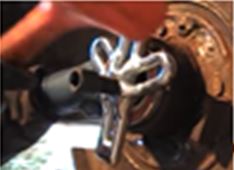
- Once Puller Meets Housing Reverse Puller and Use Washer on Front Edge of Bearing.
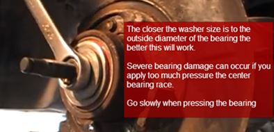
- Apply a Small Amount of Tension and Tap With Mallet.
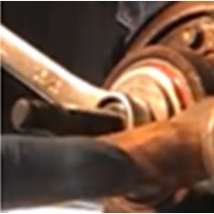
- New Bearing Fully Seated Into Wheel Carrier.
File:New_Bearing_Fully_Seated_Into_Wheel_Carrier.JPG|300px|center]]
- Install new Snap Ring (Cir-Clip). The BMW video makes this look easy!
File:Install_new_Snap_Ring.JPG|300px|center]]
- Reinstall Parking Brake.
- Add Anti-Seize To Inside Surface of Bearing.
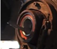
- Prepare Plumbing Flange, Washers and Bolt.
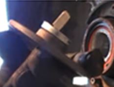
- Place Through Wheel Carrier From Back.
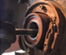
- Place Rear Axle Shaft Flange Over Puller Bolt from Front.
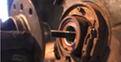
- Use Washer and Nut to Press Rear Axle Shaft Flange Into Wheel Carrier Housing.
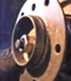
- Screw Rear Axle Shaft Flange Into Wheel Carrier Housing.
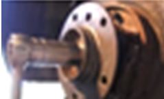
- Place Wheel carrier on Axle Shaft and Reinstall (E14).
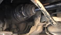
- Apply Anti-Seize to Rear Axle Shaft Flange Face.
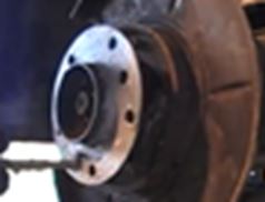
- Reinstall Disk Rotor with Screw.
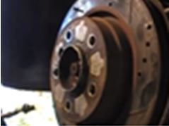
- Use Mallet to Ensure Even Seating of Disk Rotor.
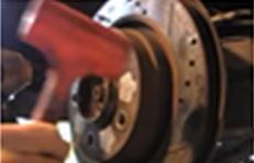
- Reinstall Brake Calliper.
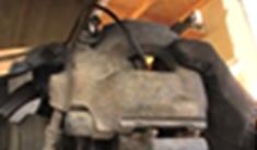
- Apply Anti-Sieze to Axle Thread.
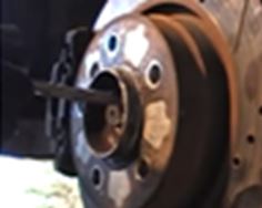
- Prevent Rotor From Turning With Allan Key or Parking Brake and Torque Axle Collar nut (350Nm).
- Stake Axle Collar Nut Locking Mechanism.
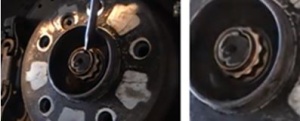
- Reinstall Sway Bar (Both Sides).
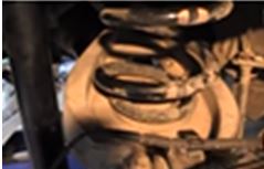
- Reinstall Wheel Carrier into Vehicle.
Reinstalled Wheel Carrier, New Discs and Brake Pads
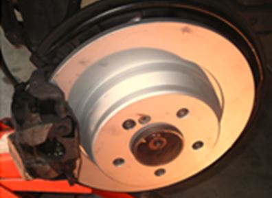
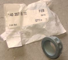
- Reinstall Axle Collar Nuts. These are one use only and must be replaced each time.
- Torque Required is 350 Nm. 350 Nm is way beyond the maximum capability of my torque wrench so I used my own weight and my breaker bar.
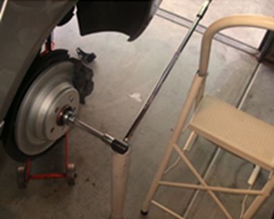
- To achieve 350 Nm torque requires my 94Kg weight to be applied at 380mm.
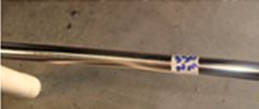
- Torque Calculation.
- Torque [Nm]/(Weight [Kg]x g [m/s2]) = Distance [m]
- The Earth’s Gravitational Constant, g = 9.8 [m/s2])
- So for T = 350 Nm,
- W = 94 Kg
- Then D = 350/(94 x 9.8) = 0.38m
- Torque Axle Collar Nuts. I smoothly applied my 94Kg weight at the 0.38m mark on the breaker bar, without jumping. The breaker bar was supported at the fulcrum point with a length of hard plastic pipe.
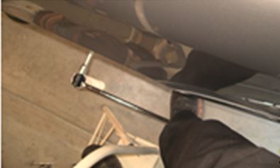
- Axle Collar Nut Torque ‘Calibration’. I tested my weight torqueing method using the old axle collar nut and then tried removing it as I had done originally. It seemed about the same amount of effort required, ie the nut took almost as much force as I could muster to lift the end of my breaker bar to undo the 350 Nm collar nut.
- Stake the Axle Collar Nuts. Even though the original axle nuts were not staked in place I decided to do so just for added security.
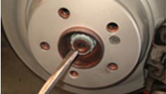
Adjust Parking Brake Thumbwheel
- Turn the parking brake thumbwheel 5 notches from the fully engaged position. (Do the same number of notches on both sides.) Test that the discs turns freely after the adjustment.
Preload Brake Automatic Cable Slack Adjuster
- Finally release the hold down clip (d) on the brake automatic cable slack adjuster. This tensions both parking brake cables.
