Crankcase ventilation cylinder head cover
 |
 |
Crankcase ventilation
Mercedes M112 V6, M113 V8 and
https://mercedessource.com/store/1998-2006-v6-and-v8-engine-breather-cover-oil-leak-fix-kit
https://mercedessource.com/store/m112-m113-breather-cover-oil-leak-repair-instructions-demand-video
https://www.fcpeuro.com/products/mercedes-breather-cover-reseal-kit-m112-m113-oem-m112bcvr
For all M112 and M113 gas engines with leaking breather chamber covers on top of engine If you own a 1998 to 2006 Mercedes with a V6 (M112) or a V8 (M113) engine this is one job you will have to deal with at some point. Just pull the top cover off your engine and look. Even cars with low mileage may have oil seeping out the breather covers on the top of the heads. Doing a proper reseal on these covers is not hard but it is tedious if you don't want them to leak again. This is one job if you want it done right you should consider doing it yoursel!!!
Even more so than needing the correct sealant, you will need to make sure the sealing surfaces are ABSOLUTELY clean of any dirt, oil, or moisture BEFORE you apply the new CORRECT sealant. This kit contains supplies and instructions on how to do just that.
Kent removes the right side breather cover on a W220 S500 and takes you through the process step by step.
Removing the cover from the engine Inspecting the sealing surfaces for leaks Intial cleaning for the dirt and old sealant 2nd level cleaning of the oil and grease Tools and supplies to use to avoid damaging the surface of the magnesium parts 3rd level and final deep cleaning Replacement of the original aluminum bolts Cleaning the valve cover long bolts Proper application of the sealant Reason for quick assembly Using a torque wrench for final tightening of the bolts Inspection and final wrap up
The replacement stainless steel bolts in this kit are the correct metric thread and length. Rather than a torx head the bolts had a 5 mm hex head.
N000912005010 x5
Remove/install cover for crankcase ventilation (WIS instruction)
ENGINES 112, 113
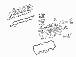
Shown on engine 113:
|
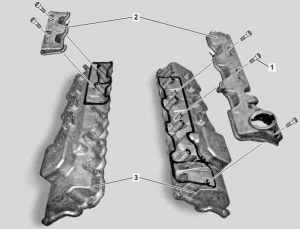
|
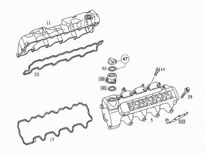
Sealant path - Shown on engine 113:
|
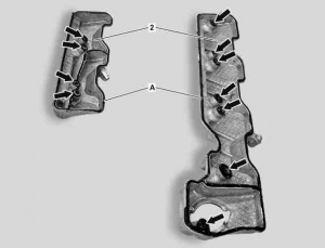
|
Work instructions:
- Aluminum bolts (1). Installation: Install new bolts.
- Clean. When cylinder head covers are installed, cover oil ducts with rags. Do not use any sharp-edged tools or abrasive paper as this will damage the sealing surfaces. Oil channels clogged with sealant will damage the engine. Cleaning materials: Loctite 7200 or Loctite 7063 cleaning spray 150 ml (A001986717110).
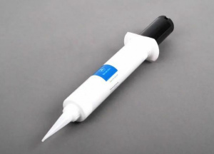
- Sealant. Apply a 2.0 mm thick bead of sealant (A), observing the bolt holes (arrow). Do not spread the silicone bead. Process sealant within 10 minutes. To avoid leaks, use only the silicone sealant specified in the repair materials - Loctite 5970 sealant (A0039899820)!
Torque specification:
- Bolt, crankcase ventilation cover to the cylinder head valve cover: 4 Nm (Engine 112 and 113)
Cylinder head cover
Remove/install cylinder head cover (WIS instruction)
Remove/install:
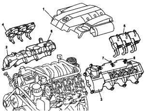
- Remove engine trim panel with integrated air filter (1). Unclip covering on front side of engine. Remove air filter by pulling vertically up and off the cylinder head covers.
- Remove air filter (Model 215.374, 220.074/174)
- Unscrew guide tube for the automatic transmission oil dipstick
- Detach right ignition coils (4), left ignition coils (5) on right cylinder head cover (2) and left cylinder head cover (3). Except engines 112.911/914/915/917/954, Engine 113.969.
- Disconnect spark plug connectors. Installation: Observe marking for spark plug connectors on the cylinder head covers and ignition coils.
- Pull off vent hoses on right connector (6) and on left connector (7) of the right cylinder head cover (2) and left cylinder head cover (3).
- Pull off engine vent hose on left connector (8) of left cylinder head cover (3).
- Disconnect fuel line at fuel rail. Only on vehicles with rigid fuel line and: Model 211.061/065/070/076/276, Model 215.374, Model 220.074, Model 230.474/475. Release fuel pressure through service valve!
- Remove right cylinder head cover (2) and left cylinder head cover (3). Installation: Check cylinder head covers for leaks, see: Ensure cylinder head cover gasket is correctly installed.
- Install in the reverse order
- Check for leaks with engine running
Torque specifications:
- Cylinder head cover bolt: 9 Nm (Engine 112 and 113)
- Bolt, ignition coils to cylinder head cover: 8 Nm (Engine 112 and 113)
- Fuel feed line to fuel distributor: 38 Nm (Engine 112 except 112.945/951/960/961)
- Fuel feed line to fuel distributor: 38 Nm (Engine 112.945)
- Fuel feed line to fuel distributor: 35 Nm (Engine 112.960/961 AMG)
- Fuel feed line to fuel distributor: 38 Nm (Engine 113.940/941/942/943/944/945/946/948/960/961/962/963/964/965/966/967/968/969/971/980/981/982/984/986/988)
- Fuel feed line to fuel distributor: 38 Nm (Engine 113.987)
- Fuel feed line to fuel distributor: 38 Nm (Engine 113.990/991)
- Fuel feed line to fuel distributor: 38 Nm (Engine 113.992/993/995)
Ensure gasket of cylinder head cover is correctly installed:
|
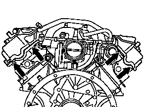
|
