Steering linkage
DIY
Check track rod and drag link linkage for play, check rubber boots
|
|
|
- Switch off ignition
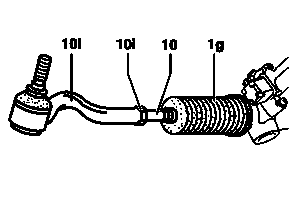
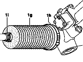
- Check boots (1g). Never check the boot (1) by pressing in or around the ribs. This will cause damage to the plastic and then result in leakage. Raise vehicle at front axle. Stretch bellows by turning the steering to the left and right while checking for damage (cracks, chafing marks and dents). If damaged, the boot (1g) must be replaced.
- Check tie rod ball joint for play. Inspect tie rod joints by pulling and pushing firmly. In event of play on tie rod ball joint the tie rod (10) is to be replaced.
- Check rubber boots of tie rod ends (10l) for signs of leaks and condition. If a rubber boot leaks replace tie rod (10).
Remove/install track rod
Shown on model 220
|
|
- Remove front wheel
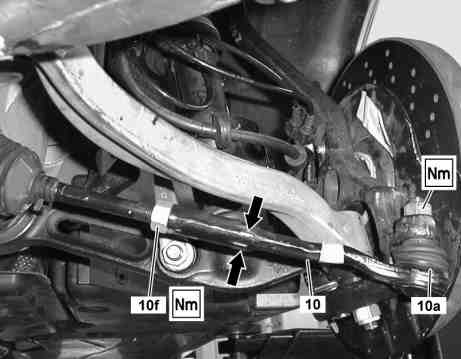
- Pry off tie rod joint (10a) from steering knuckle assembly. Installation: Replace self-locking nut.
- Release locknut (10f) and unscrew track rod (10). Counterhold tie rod (10) for loosening the jam nut (10f) (arrow).
- Install in the reverse order
- Perform chassis alignment (wheel toe-in alignment)
Torque specifications:
- Self-locking nut, tie rod to steering knuckle: 1st stage: 50 Nm, Stage 2: 60°
- Lock nut, tie rod to inner tie rod: 60 Nm
 |
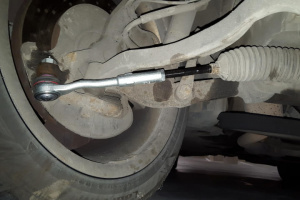 |
Pressing out and attaching track rod joint at steering knuckle
Shown on model 220
|
|
|
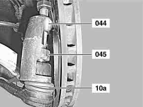
- Pushing off: Undo self-locking nut of tie rod joint (10a).
- Mount thrust piece (045).
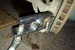
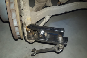
- Pry off tie rod joint (10a) using puller (044). Puller (044) 220589003300 with press 163589034300 for model 215, 220, 230 without code (P99) Special model "AMG Black Series". Do not damage boot, otherwise lubricant would leak out of the tie rod joint (10a) This results in increased wear.
- Remove puller (044) and thrust piece (045).
- Install: Clean tapered connection. Grease or oil must not be present at the cone and thread, as otherwise the tie rod joint (10a) could work its way loose.
- Replace self-locking nut and tighten. Counter ball head with an Allen wrench if necessary.
Remove/install inner tie rod with axial joint
Shown on model 220
|
- Remove front wheel
- Turn steering wheel to the side that is being worked on
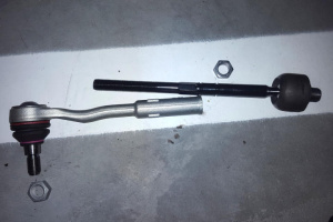
- Remove tie rod
- Remove bellows
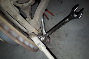
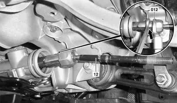
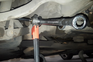
- Counter gear rack (arrow). Use open end wrench (width across flats 27 mm).
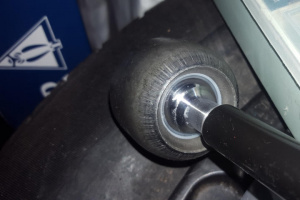
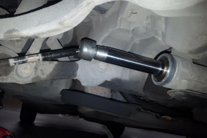
- Remove inner track rod with axial joint (12). Do not use force (hammer blows, severe leverage), use open wrench (012).
- Install in the reverse order
Torque specification:
- Inner track rod with axial joint to rack-and-pinion joint: 110 Nm
 |
 |
 |
 |
Check and replace rubber boot
Shown on model 220
|
|
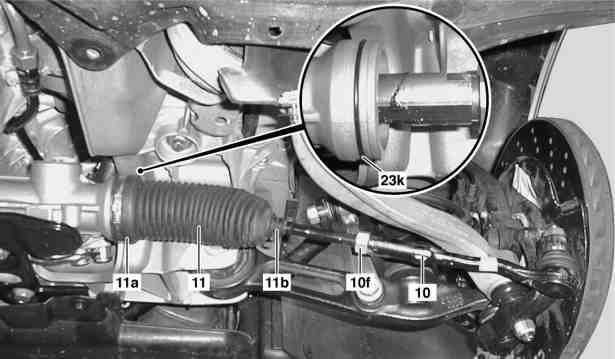
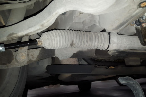
Checking: Check left and right boot (11). Never check bellows (11) by pressing in or around the plastic bead. This results in damage to the bellows (11) and causes leaks. Perfect sealing of the bellows is absolutely vital for correct functioning of the rack-and-pinion steering, so perform the visual inspection as follows: Raise vehicle at front axle. Stretch the bellows (11) by turning the steering through left and right lock and in the process check for damage (cracks, chafing marks and intrusions) and replace if necessary.
Remove/install:
- Detach lower engine compartment paneling (Vehicles with gasoline engine)
- Remove bottom section of soundproofing (Vehicles with diesel engines)
- Remove track rod (10)
- Unscrew lock nut (10f)
- Detach outer clamp (11b)
- Detach inner clamp (11a)
- Pull off bellows (11). Installation: Replace O-ring (23k).
- Check steering rack and inner tie rod thrust joint for corrosion and play.
- If the steering is leaking and the steering rack is already corroded, the rack-and-pinion steering must be replaced complete, in order to guarantee a satisfactory function.
- In order to guarantee satisfactory operation of the steering, the inner tie rod should be replaced when the axial joint is worn.
- Install in the reverse order
Detaching and attaching inner clamp
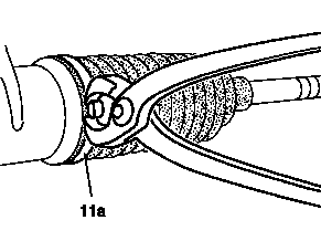
- Remove: Remove inner clamping collar (11a) with side-cutting pliers.
- Install: Fit new inner hose clamp (11a) and tension with commercially available clamp pliers.
- Check that inner hose clamp (11a) is seated correctly.
|
 |
Locate noises from the steering
Example shown on model 204
|
|
Example shown on model 211 front axle
|

|
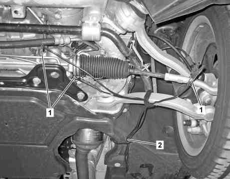
- Attach clamp pliers with microphone (1). Attach the clamp pliers as close as possible to suspect components. For evaluation purposes (normal noise - defect noise) listen to the same components, e.g compare noise from left supporting ball joint with right supporting ball joint. Up to 6 clamp pliers with microphone can be attached. Attach clamp pliers so that while driving the freedom of movement of chassis components is not impaired. Warning! It is essential to check whether the clamp pliers impair the steering function. Risk of accident! Ultrasonic leak detector and Noise diagnosis
- Fasten line (2) of clamp pliers with microphone (1) (arrows). Fasten the lines with velcro strip, cable ties or adhesive tape. Route the lines so that while driving the freedom of movement of the chassis components is not impaired.
- Guide line (2) of clamp pliers with microphone (1) into the interior. Route the lines so that contact with the road is ruled out. Route lines so that damage by a door or window is ruled out.
- Connect line (2) to the selection switch (3). The lines and connectors on the selection switch are color coded. Note the color assignment of components which are to be listened to.
- Carry out road test for noise diagnosis. Warning! Only carry out road test with a second person present. The headphones must not be worn by the driver.
- Locate defective components by listening to the microphone. Danger! Reduce the volume before each channel change otherwise hearing can be damaged If necessary: Replace faulty components.