Rear doors
Parts
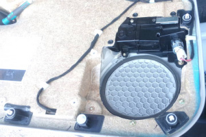
Cigar lighter
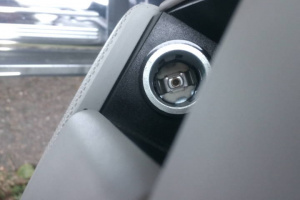
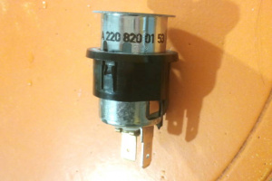
Part number for cigar lighter is A2208200153 (replaced by A2208200353). The 12v power to cigar lighter is provided by door control module. The power is cut off when the ignition is switched off.
 |
 |
 |
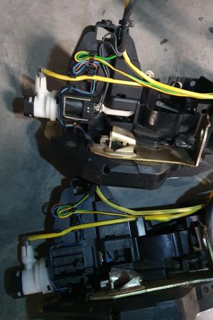
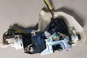
Door lock
Door locks vary based on option codes 883 - POWER CLOSING SYSTEM and 889 - KEYLESS-GO. Keyless-Go locks have an additional electrical connector.
 |
 |
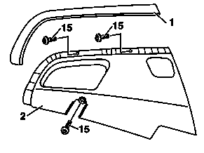
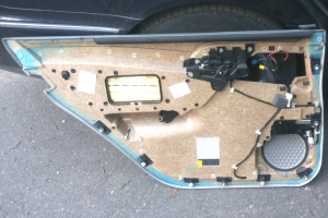
Remove/install door lining on rear door
|
|
|
|
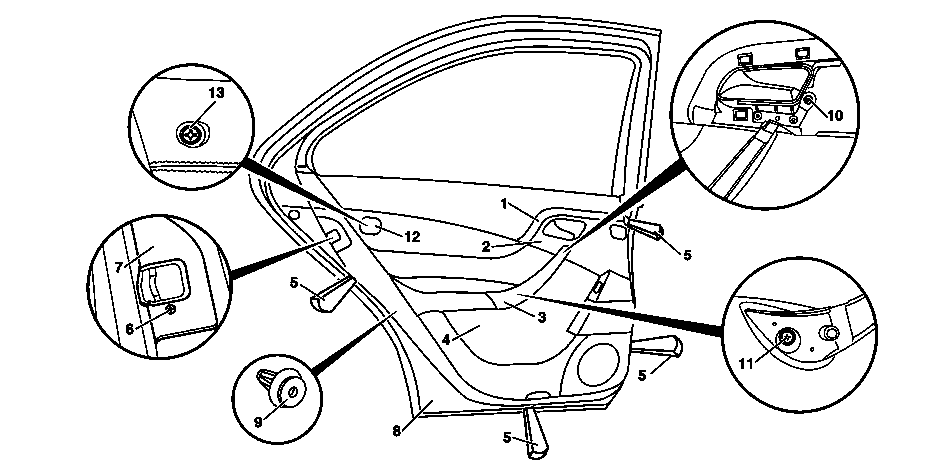
- Press trim strip (1) off of door control module covering (2) with mounting wedges (5).
- Remove door handle cover (3) from door handle
- Unscrew bolts (15) and press door control module covering (2) out of door lining (4) with mounting wedges (5) and remove
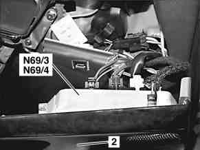
- Disconnect connectors from left rear door control module (N69/3) and right door control module (N69/4) and remove door control module covering (2)
- Unscrew bolt (6) from lock cover plate (7) and remove lock trim surround (7).
- Remove cover (12) and unscrew bolt (13)
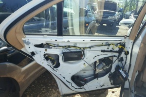
- Press door lining (4) off of inner door panel (8) with mounting wedges (5). Move mounting wedges (5) directly to clip retainer (9) so that the retainer tab of the clip retainer do not tear out off the door lining.
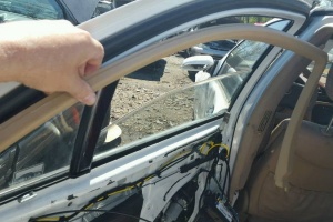
- Pry door lining (4) out of retaining clamps on at top of sealing rail with mounting wedges (5) and simultaneously remove from inner door panel.
- Unhook control cable from inside door opener.
- Disconnect electrical connectors from door lining (4) and lay down door lining (4).
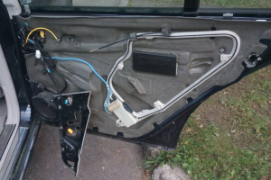
- Check insulating mat and clip retainers (9). Replace damaged insulating mat and clip retainers.
- Install in the reverse order. Installation:Remove clip retainers still on inner door panel (9) and install at corresponding point on door lining.
 |
 |
 |
 |
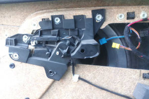 |
Removing and installing door lock on rear door (as of 01/09/1999)

|
|

|
|
Removing:
- Removing and installing door liner on rear door
- Remove door insulation in area of door lock
- Remove control cable (31) for inner door actuation. For this purpose unhook control cable (31) from holder (34) first and then unclip from door lock (33).
- Unclip cover (35) for transfer lever (40) from inner door panel (it might be attached with rivet and cannot be removed entirely)
- Remove retaining rod (32) together with transfer lever (40). For this purpose unscrew plastic screw (39) and unclip spreading clip on transfer lever (40) from inner door panel.
- Remove CL line (37) from separation point (41)
- Remove outer door handle and bearing bracket from rear door. Note: Door handle and bearing bracket must be removed before removing door lock. See instructions in the section below.
- Unscrew door lock (33). For this purpose unscrew three screws (38).
- Remove door lock (33) from inner door panel through installation opening (because of narrow space, this process requires to apply some wiggling and little force)
Installing:
- Install door lock (33) on inner door panel through installation opening
- Screw in screws (38) in door lock (33). Tighten front screws (38) first.
- Install CL line (37) on separation point (41)
- Install outer door handle and bearing bracket on rear door
- Install retaining rod (32) together with transfer lever (40). For this purpose clip spreading clip on transfer lever (40) into inner door panel and screw in plastic screw (39).
- Clip cover (35) for transfer lever (40) into inner door panel.
- Install control cable (31) for inner door actuation. For this purpose hook control cable (31) into door lock (33) first and clip holder (34) in on door lock.
- Check clearance. Pull door handle until resistance can clearly be felt.
- Glue on door insulation
- Install door liner on rear door
- Carry out operational check
- Rear door - Screw on door lock: 10 Nm
- Test and adjustment values for front door - Clearance: 2(+-1)mm
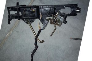
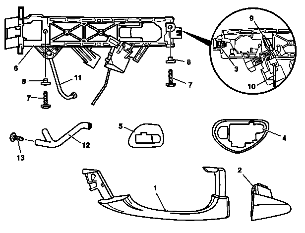
Removing and installing outer door handle and bearing bracket on rear door (as of 01/09/1999)
|
|
|
|

|
|
Removing:
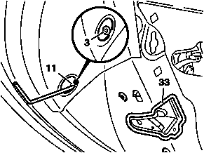
- Remove cover on opening (11) above door lock (33)
- Loosen Torx screw (3) approx. 5 turns. Accessible through opening (11).
- Remove door liner from rear door
- Remove door insulation
- Disconnect connectors. Depending on vehicle equipment also Keyless go antenna.
- Remove guide (2). Slightly pivot guide (2) to rear and then pull out to outside, simultaneously pull up handle (1) slightly. Avoid damaging paint.
- Remove handle (1). For this purpose pull handle (1) out of bearing bracket to rear together with base (4) and remove from door passage.
- Remove base (5)
- Remove insulating mat (16) in area of door lock
- Unscrew screws (7) on door handle recess
- Remove connecting rods to door lock. See section "Removing and installing connecting rods to door lock" below.
- Remove bearing bracket (6). Remove bearing bracket (6) through installation opening in inner door panel.
Installing:
- Install bearing bracket (6). Install bearing bracket (6) in inner door panel through installation opening.
- Install connecting rods to door lock. Install release rod (10) in retainer. Install connecting rod (11) in retaining lug and catch. Screw in screws (7) in door handle recess.
- Screw in screws of door lock (33)
- Lock retainer on release rod
- Install base (5)
- Install handle (1) in bearing bracket (6) together with base (4). Ensure that the lever on the handle (1) slides behind the actuation lever (9) of the bearing bracket (6) to allow the door lock to be unlocked.
- Install guide (2)
- Turn in Torx screw (3) WAF4 mm and tighten
- Check clearance. Pull handle (1) until resistance can clearly be felt.
- Adjust clearance between handle (1) and actuation lever (9). If required press release rod (10) upward retainer by opening retainer until resistance can be felt. Then relock retainer.
- Carry out operational check
- Insert insulating mat (16)
- Glue on door insulation
- Install door liner on rear door
- Carry out operational check
- Rear door - Screw on door lock: 10 Nm
- Rear door - Screw for door handle on rear door: 3 Nm
- Test and adjustment values for front door - Clearance: 2(+-1)mm
Removing and installing connecting rods to door lock
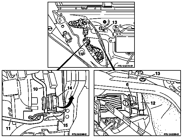
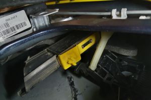
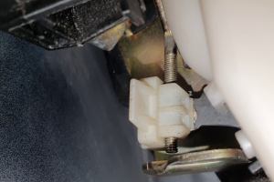
- Unscrew sheet metal screw (13) and remove spacer (12) from bearing bracket (6).
- Press lug for retainer (14) to outside (arrow) and remove release rod (10) from retainer (14).
- Unhook connecting rod (11) from retaining lug (15) on door lock.
The connecting rod (11) can only be unhooked when the bearing bracket (6) is loose.
 |
 |
Removing and installing connectors
Disconnect connectors depending on vehicle equipment:
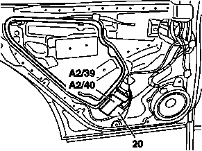
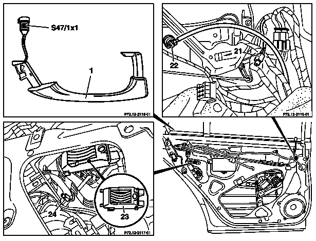
- Unscrew mounting screws (20) from Keyless go rear door antenna (A2/39, A2/40), carefully unclip antenna and lay down to side.
- Remove coupling (21) out of coupling strip together with gray leads and disconnect clutch.
- Unclip separation point (22) from vacuum line and remove vacuum line.
- Remove cover (23) and disconnect capacitive sensor and push contact connector (S47/1x1).
- Remove microswitch (24) from door lock.
Remove/install switches for power window in rear doors
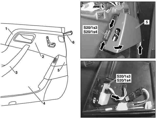
- Press molding strip (1) out of door control module cover (2) on driver's door with assembly wedge (6)
- Remove door handle cover (3) from door handle
- Unscrew door control module cover (2) from door liner (4) of driver's door and press off with assembly wedge (6)
- Unclip switch cover (5) from door liner (4). For this purpose open ashtray in rear door and lift switch cover (5) until switch cover (5) can be pivoted over switch. Move switch cover (5) out of retaining clip (arrow) and remove switch cover (5).
- Disconnect connector from left/right power window switch (S20/1s3, S20/1s4).
- Unclip left/right power window switch (S20/1s3, S20/1s4) from ashtray housing. For this purpose press retaining lugs for switch (arrow) together with suitable tool and remove switch toward rear.
- Install in the reverse order
- Carry out function check
Up to 31/08/1999
Removing and installing door lock on rear door (up to 31/08/1999)
|
|
|
|
Removing:
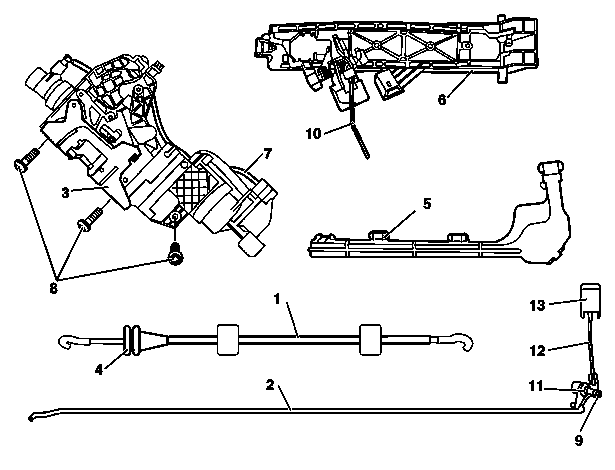
- Removing and installing door liner on rear door
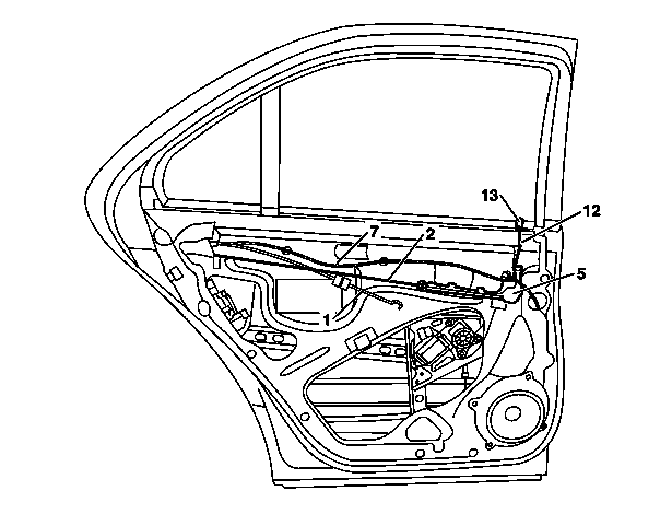
- Remove insulating mat in area of door lock (3)
- Remove control cable (1) for inner door actuation. For this purpose unhook control cable (1) from door lock (3) first and unclip holder (4) from door lock.
- Unclip cover (5) for transfer lever (11) from inner door panel
- Remove retaining rod (2) together with transfer lever (11) and retaining rod (12). For this purpose unscrew screw (9) and unclip spreading clip on transfer lever (11) from inner door panel.
- Remove outer door handle from rear door. It is not possible to remove the bearing bracket (6) when the door lock (3) is installed.
- Unscrew bearing bracket (6) and push upward. Unscrew screws from door handle recess and open retainer for release rod (10).
- Remove CL line (7) from door lock (3)
- Unscrew door lock (3). For this purpose unscrew screws (8).
- Remove door lock (3) from inner door panel through installation opening
Installing:
- Install door lock (3) on inner door panel through installation opening. First insert bearing bracket (8) in door above door lock.
- Screw in screws (8) in door lock (3). Tighten front screws (8) first.
- Install CL line (7) on door lock (3)
- Install bearing bracket (6). Install release rod (10) in door lock (3) retainer. Screw in screws in door handle recess.
- Install outer door handle on rear door
- Install retaining rod (2) together with transfer lever (11) and retaining rod (12). For this purpose clip spreading clip on transfer lever (11) into inner door panel and screw in screw (9).
- Clip cover (5) for transfer lever (11) into inner door panel
- Install control cable (1) for inner door actuation. For this purpose hook control cable (1) into door lock (3) first and clip holder (4) in on door lock (3).
- Adjust clearance between door handle and actuation lever. Push release rod (10) upward until resistance can be felt with retainer open. Then relock retainer.
- Check clearance. Pull door handle until resistance can clearly be felt.
- Glue on insulating mat
- Install door liner on rear door
- Carry out operational check
- Rear door - Screw on door lock: 10 Nm
- Test and adjustment values for front door - Clearance: 2(+-1)mm
Removing and installing outer door handle on rear door (up to 31/08/1999)
|
|
|
|
Removing:
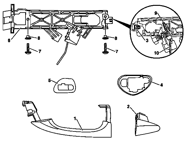
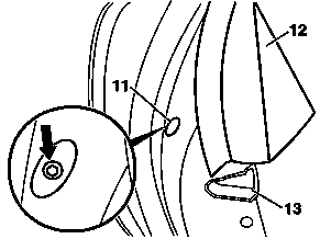
- Pull door sealing frame (12) out of channel in area of door lock (13)
- Loosen torx screw (3) approx. 5 turns. Accessible through opening (11) on narrow side of door (arrow).
- Remove guide (2). Pivot guide (2) slightly backward and then pull out to outside, simultaneously pull up handle (1) slightly. Avoid damaging paint.
- Remove handle (1). For this purpose pull handle (1) out of bearing bracket to rear together with base (4) and remove from door passage.
- Remove base (5)
- Remove insulating mat in area of door lock
- Remove door liner from rear door
- Unscrew screws from door lock (13). Open retainer for release rod (10). Door lock can remain in door.
- Remove bearing bracket (6). Unscrew screws (7) from door handle recess. Remove bearing bracket (6) together with release rod (10) through installation opening in inner door panel.
Installing:
- Install bearing bracket (6). Install bearing bracket (6) together with release rod (10) through installation opening in inner door panel and insert release rod (10) into retainer on door lock (13). Screw in screws (7) in door handle recess.
- Screw in screws in door lock (13)
- Install base (5)
- Insert handle (1) into bearing bearing bracket (6) with base (4). Ensure that the lever on the handle (1) slides behind the actuation lever (9) of the bearing bracket (6) to allow the door lock to be unlocked.
- Install guide (2)
- Turn in Torx screw (3) WAF 4 mm and tighten
- Install door sealing frame (12)
- Adjust clearance between handle (1) and actuation lever (9). Push release rod (10) upward until resistance can be felt with retainer open. Then relock retainer.
- Check clearance. Pull handle (1) until resistance can be clearly felt.
- Carry out operational check
- Glue on insulating mat. Replace damaged insulating mat.
- Install door liner on rear door
- Carry out operational check
- Rear door - Screw on door lock: 10 Nm
- Rear door - Screw for door handle on rear door: 3 Nm
- Test and adjustment values for front door - Clearance: 2(+-1)mm
