EVAP system: Difference between revisions
(Connection diagram for evaporative emission control system) |
No edit summary |
||
| Line 1: | Line 1: | ||
The Evaporative Emission Control System (EVAP) is used to prevent gasoline vapors from escaping into the atmosphere from the fuel tank and fuel system at all times. | |||
<!-- https://www.nyvip.org/PublicSite/OBDII/evap.html --> | |||
A typical system consists of the fuel tank, an EVAP vapor storage canister full of charcoal, valves, hoses and a sealed fuel tank gas cap. The EVAP system is designed to stop fuel system fumes from leaking directly into the atmosphere. Vent lines from the fuel tank pass vapors to the vapor canister, where they are trapped and stored until the engine is started. When the engine is warm and the vehicle is going down the road, the PCM then opens a purge valve allowing the vapors to be drawn from the storage canister into the intake manifold. The fuel vapors are then burned in the engine along with the air/fuel mixture. | |||
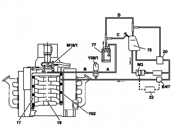
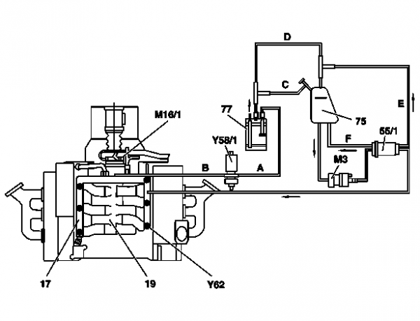
== Connection diagram for evaporative emission control system (M113) == | == Connection diagram for evaporative emission control system (M113) == | ||
<!-- AR47.30-P-8212-01DI, Connection diagram for evaporative emission control system --> | <!-- AR47.30-P-8212-01DI, Connection diagram for evaporative emission control system --> | ||
| Line 17: | Line 22: | ||
* Y58/1 - Purge control valve | * Y58/1 - Purge control valve | ||
* Y62 - Fuel injection valves | * Y62 - Fuel injection valves | ||
|[[File: | |[[File:W220_EVAP_system_diagram_M113.png|600px]] | ||
|} | |} | ||
Revision as of 00:48, 24 September 2021
The Evaporative Emission Control System (EVAP) is used to prevent gasoline vapors from escaping into the atmosphere from the fuel tank and fuel system at all times.
A typical system consists of the fuel tank, an EVAP vapor storage canister full of charcoal, valves, hoses and a sealed fuel tank gas cap. The EVAP system is designed to stop fuel system fumes from leaking directly into the atmosphere. Vent lines from the fuel tank pass vapors to the vapor canister, where they are trapped and stored until the engine is started. When the engine is warm and the vehicle is going down the road, the PCM then opens a purge valve allowing the vapors to be drawn from the storage canister into the intake manifold. The fuel vapors are then burned in the engine along with the air/fuel mixture.

