From W220 S-Class Encyclopedia
Jump to navigation
Jump to search
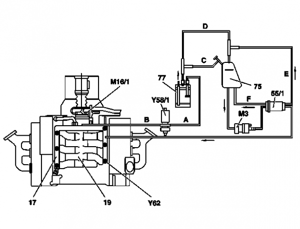
Connection diagram for evaporative emission control system (M113)
|
Shown on engine 113 from 09/97 in model 210
- 17 - Fuel distributor
- 19 - Intake manifold
- 75 - Fuel tank
- 77 - Activated charcoal canister
- A - Activated charcoal canister line to purge control valve
- B - Purge control valve line for to intake manifold
- C - Vent line from activated charcoal canister to fuel tank
- D - Line for activated charcoal canister vent valve to fuel tank
- M3 - Fuel pump
- M16/1 - EA/CC/ISC [EFP/TPM/LLR] actuator (only models 129, 210)
- Y58/1 - Purge control valve
- Y62 - Fuel injection valves
|
|
Connection diagram for evaporative emission control system (M112)
|
Shown on engine 112 from 09/97 in model 210
- 17 - Fuel distributor
- 19 - Intake manifold
- 45 - Filler neck (with connection for on-board refueling vapor recovery ORVR)
- 55/1 - Fuel filter
- 75 - Fuel tank
- 77 - Activated charcoal canister
- M3 - Fuel pump
- M16/1 - EA/CC/ISC [EFP/TPM/LLR] actuator (only models 129, 210)
- Y58/1 - Purge control valve
- Y62 - Fuel injection valves
- A - Activated charcoal canister line to purge control valve
- B - Purge control valve line for to intake manifold
- C - Activated charcoal canister line to fuel tank
- D - Fuel tank line to activated charcoal canister
- E - Fuel filter degassing line to fuel tank
- F - Fuel filter fuel tank fuel return line to fuel tank
|
|
