DIY High Current Sensor - Quiescent Current or Parasitic Discharge Tests
Back to: WIS 54.10 Battery, Power Supply, Voltage Converter
Original Document
W220 2003 S500L How to Measure Quiescent Current Draw by BenzWorld Member ricebubbles
Revisions
2012-05-29 Version 01: Original Document 2014-02-07 Version 02: Added the observed voltage drop readings for individual fuses with a 30mA quiescent current drain.
References
The references for this DIY were the BenzWorld Forum and the Star Diagnosis System (SDS), Xentry, Workshop Information System (WIS).
Introduction
The W220 is particularly prone to large quiescent current draw, often called parasitic current drain through it’s proliferation of electronic circuits some of which are constantly activated. Sometimes the electronic circuits can develop issues and become heavy continuous users of battery power. When the car has been locked and has fully gone to sleep (takes at least twenty minutes) the quiescent drain from the car battery must not exceed 0.05A or 50mA.
If you find that the battery is constantly going flat or the unlocking system seems to take a long time to respond, it could be that you have a low voltage battery caused by excessive quiescent current draw. The following tests will help determine which components are causing the problem.
It is a good idea to start with the obvious and first test the car battery charging function and the car battery itself, before embarking on the more detailed quiescent current tests.
Testing Car Battery Charging Function
After a good drive of 60 minutes or so the car battery should be fully charged and read at least 14.2V with the car running and the charger operating. Turn off large power consumers such as headlights for this test. If the battery does not have a healthy voltage, suspect the alternator and associated charging circuits.
Testing Car Battery
A simple test on the car battery is to measure the voltage first thing in the morning after the vehicle has been sitting asleep for twelve hours or so. The night before, set up your voltmeter on long leads so that the boot/trunk lid can be closed and the car locked. Place the voltmeter outside the vehicle and do not activate any functions prior to taking your reading.
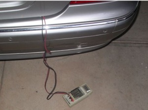
The voltage should be at least 12.4V. If not then the battery is most likely on its last legs. Note my W220 2003 Update S500L still had the original battery dated March 2003, in use in 2012, ie nine years of use. The battery was showing signs of age as the voltage would drop below 12V just after unlocking and with the boot/trunk lights operating. Make sure to rectify a weak battery condition quickly as you do not want to be replacing an over worked alternator as well.
You can also test the battery itself with a hydrometer or by performing a load test. Either will show a battery that has outlived its usefulness. There is a pretty good tutorial on batteries at: http://www.batterystuff.com/tutorial_battery.html and another one for the hydrometer test at: http://autorepair.about.com/library/.../aa101604c.htm.
There's a "poor man's load test" video at:
Testing Car Battery Quiescent Current Draw/Load
If you have replaced the battery or checked that the existing one is in good condition and you are still experiencing low voltage first thing in the morning, it could be that one or other of the electronic circuits has developed an issue and is consuming more power than it should. The quiescent current tests should confirm this situation and allow diagnosis of the faulty component.
Specified W220 Quiescent Current Draw/Load
Reference: Star Diagnosis System (SDS), Xentry, Workshop Information System (WIS). The quiescent current at the battery terminal for a W220, after the car has been locked for at least 20 minutes and the car has gone to sleep, should be no more than 0.050A or 50mA.
If testing at individual fuses each fuse quiescent current should be no more than 0.020-0.030A or 20-30mA.
How To Measure Quiescent Current Draw/Load
There are several good links to testing car battery quiescent current draw (also called parasitic drain). http://www.benzworld.org/forums/w220-s-class/1491289-how-measure-quiescent-current-battery-die.html
How to Find a Parasitic Battery Drain - wikiHow
However this is my version.
Manufacture A Current Sense Resistor
Because the current drawn from the car battery during testing can be substantial, eg if you use the lock/unlock function during the test when the current can momentarily exceed 20A, you really need a special Digital Current/Amp Meter with a high and low range for current sensing. My Digital Multi Meter (DMM) limits at 2A at the top of the range so would probably be damaged if it accidentally sustained higher currents during the testing. However my DMM in DC voltage mode, ie when used as a Digital Volt Meter (DVM), is quite sensitive and will read 0.1999V or 199.9mV maximum on the lowest scale and hence is quite suitable, if used with an appropriate value resistor, to monitor small and large currents. It is quite easy to make a Current Sense Resistor which doesn’t introduce significant voltage drop during current testing and which is able to sustain high currents during temporary overloads.
The first task is to make the current sense resistor out of scrap workshop materials. I used about 250mm of light gauge (1.3mm dia.) galvanised twitching wire. Wind this around a broom handle to make a crude coil. Clamp the ends in an electrical connector block. Make two connecting wires out of two pieces of heavy gauge insulated copper wire with alligator clips soldered to one end and the other end stripped, tinned with solder, and placed into the electrical connector block. Leave about 6mm of these wire ends exposed so that you can clip on your DVM. This will read the very small voltage drop which occurs across the twitching wire when it is inserted into the circuit, and once calibrated, will give you the actual current draw.
Leave the sensing coil exposed because it may get slightly warm with large currents such as 20A flowing and be careful where you place it so that it doesn’t burn anything.
It is not necessary to electrically insulate the sensing coil if you insert it into the negative or earth end of the car battery. Just be aware that it is conducting electricity and try to avoid letting it touch any parts of the car chassis at 0V or earth potential. Of course once connected, do not let it touch any higher voltages.
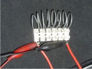
Calibrate The Current Sense Resistor
Because the actual resistance of your Current Sense Resistor will not be an exact nice value and will be a different value for each coil made, it is necessary to calibrate it. The idea is to pass a known current (anything from 0.1-2A or 100-2,000mA) through the Current Sense Resistor and measure both the actual current and voltage as accurately as possible.
What I did was use a variable power supply, (if you don’t have one of these a car battery or otherwise will do), connected to about a 1W load such as a car dome light globe or parking globe. Insert the Current Sense Resistor into the circuit as well. Measure the current draw using a DMM or an ammeter whilst simultaneously monitoring the voltage drop across the Current Sense Resistor using another DVM if possible. If you can’t beg or borrow a second DVM it is OK to first measure the current and then remove and measure the voltage. The result will not be as accurate but we are not chasing a Gold Medal here. In my case I measured 0.144V or 144mV for a 1.97A or 1,970mA load.
Using Ohms Law we can calculate the actual resistance of the Current Sense Resistor: 0.144V divided by 1.97A = 0.0731Ω or 73.1mΩ.
Then using Ohms law again (in a spread sheet is a good idea) calculate the equivalents for some round number values of mV and mA. This way when you make a measurement you can get an approximate idea of how much current is being measured by quickly checking the Conversion Chart. A more precise value can be calculated later.
Hence a Simple Conversion Chart for my Current Sense Resistor is:
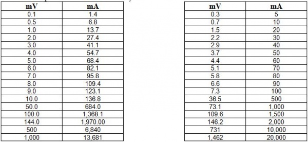
You can see by inserting the Current Sense Resistor into the circuit only a 1V voltage drop is caused by 13.7A flowing. Or 10A will cause a 0.7V drop. Even for these large currents the car will not really notice the voltage drops, (remember the battery varies from 12.4 to 14.2V anyway). For a quiescent current of 0.050A or 50mA the corresponding voltage drop will only be 0.0037V or 3.7mV.
If you lock/unlock the doors and the car decides to run the PSE Pump while you have the Current Sense Resistor installed, and complains of low battery voltage, just wait until the large currents drop back to quiescent values again.
Prerequisites for Quiescent Current Tests
Before conducting any quiescent current tests ensure all consumers are switched off, eg: • COMAND off and CDs removed. • Doors closed. • Exterior Lamp Switch to ‘0’ (Off) position, not ‘Auto’. • Ignition Key Removed. • Interior lights off. • Interior Motion Sensor off. • Makeup Mirrors off. • Radio off. • Reading Lights off. • REST Heater not activated. • Telephone off. • Vehicle Locked.
It is important to wait at least 20 minutes for the vehicle to completely go to sleep after locking. If any circuit is activated then deactivated, wait at least another 20 minutes before retesting.
Connect The Current Sense Resistor In The Vehicle
Car Battery Quiescent Current Draw
Expose the car battery in the boot/trunk. Loosen the negative/earth connection but do not remove. Clip the current sense resistor so that it will go between the negative/earth battery terminal and the cable clamp. If you are careful you can avoid disconnecting the battery from the vehicle during this process. If the battery is even momentarily disconnected it means resetting of seats, mirrors, steering angle sensor etc. is usually required. I used a large battery charger clamp to clip onto the battery post and only separate the terminal from the post when the Current Sense Resistor is in place. (Note the polarity of the positive (red) and negative (black) leads for the DVM, although this is not critical.)
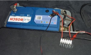
The DVM is placed outside the vehicle so that the quiescent current can be monitored with the boot/trunk lid closed and the vehicle locked. Be aware that the locking/unlocking system can draw up to 20A if the PSE motor runs. Remember that the Current Sense Resistor may get warm under these circumstances. DO NOT activate the starter motor under any circumstances! A couple of times performing this test, I found the car would not unlock using the Remote Control Key, as the voltage drop across the Current Sense Resistor was too great. Waiting usually fixes this issue but being impatient I used the mechanical key to unlock the boot/trunk and disconnected the Current Sense Resistor, remembering to avoid disconnecting the battery if possible.
Fuse Quiescent Current Draw
If the quiescent current draw at the car battery terminal is >50mA then you need to establish which circuit is taking the excess power. This means measuring the quiescent current at each fuse. (Left and Right Fuse Compartments in Engine Bay, Front Cabin Fuse Compartment and Right Rear Footwell Cabin Fuse Compartment.) Remember when checking in cabin fuses to close the door contact switches using adhesive tape.
Several simple methods are available but note withdrawing any fuse and reinserting it or inserting a test device will mean that the circuit is deactivated and then reactivated and you may need to wait at least 20 minutes before retesting this particular circuit. The Navigation is a good example and once reactivated after a fuse pull will draw approximately 0.8A or 800mA for 20 minutes, until it again reaches a standby current (quiescent) of less than 0.020A or 20mA. The Radio will also consume about 0.24A or 240mA for a short while after being reconnected.
Pull Individual Fuses Method
One method is to individually pull fuses noting any change in the total car battery quiescent current draw observed using the Current Sense Resistor when connected to the car battery as above. Wait the 20 minutes after reinserting the fuse before testing another circuit.
Measure Voltage Drop Across Individual Fuses
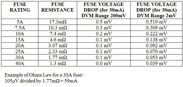
An easier technique, if you have a sufficiently accurate DVM which can read microvolts, is to measure the voltage drop across each of the fuses. This method does not disturb the circuit requiring a reset or necessitate having to wait the 20 minutes for the car to go to sleep after the first time. The quiescent current can be calculated using the voltage measured, the resistance of each fuse and Ohms Law.
Reference: WIS with observed voltage drops for a 30mA current measured by a Digital Voltage Meter.
Make a Dummy Fuse With Inbuilt Current Sense Resistor
Because I didn’t have an accurate enough DVM I made an adapter using an old blown fuse and connected it to my Current Sense Resistor constructed above. I also arranged the connector block so that the removed fuse can be inserted into the circuit in series with the current sense resistor thus still protecting the component being tested. Your Dummy Fuse With Inbuilt Current Sense Resistor will need to accommodate both large and small fuses for testing of all components.
Then all you do is individually pull fuses and insert the Dummy Fuse with inbuilt Current Sense Resistor with the fuse protection into the circuit. Wait the 20 minutes for the car to settle and then monitor the voltage drop across the Dummy Fuse and calculate the quiescent current. The result should be less than the specified value of 20-30mA in each circuit. Be careful that the exposed coil of the Current Sense Resistor does not come into contact with any metal parts as the coil will be sitting at elevated voltages near 12V.
Non-Fused Components Quiescent Current Draw
Note some components do not have individual fuse protection and must be tested independently using the same technique as for the fuses. The following are examples of components with no individual fuse protection.
- Air Bags (AB)
- Alternator
- Anti-Knock Control (AKC)
- Anti-Theft Alarm (ATA)
- Electronic Ignition System (EIS)
- Exhaust Gas Recirculation (EGR)
- Idle Speed Control (ISC)
- Ignition Switch
- Starter
Results of Car Battery Quiescent Current Draw/Load
With the boot/trunk lid open I measured 170mV across the Current Sense Resistor, which is equivalent to 2.3A and is mostly the boot/trunk lights.
With the boot/trunk lid closed the measurement immediately dropped to 23mV, which is equivalent to 0.315A or 315mA.
Five minutes later the measurement had dropped to 3mV, which is equivalent to 0.041A or 41mA.
After another five minutes the load had dropped to 2.0mV, which is equivalent to 0.027A or 27mA.
After another ten minutes (ie at the specified 20 minutes after locking the vehicle) the reading was basically the same and fluctuated from 1.9mV to 2.3mV which is equivalent to 26-31mA. The average is 29mA.
Conclusion Quiescent Current Draw/Load in Vehicle
The quiescent current draw/load or parasitic drain on the car battery in my W220 is 26-31mA, which is well within the specification of 50mA.