Fuel tank
Fuel tank
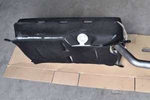
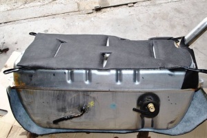
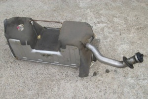
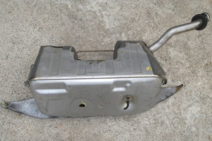
The standard fuel tank on W220 vehicles (A2204707601) has 88 liter (23 galon) volume. Vehicles with the option code 282 (SKI-BAG) or 308 (REFRIGERATOR IN REAR) have the fuel tank (A2204707701) which has volume of 78 liters (20 galons).
Vehicles with the option code 494 (U.S. VERSION) have a fuel tank pressure sensor.
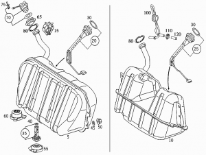
Fuel tank (88l)
 |
 |
Fuel tank (78l)
 |
 |
Location/design/function
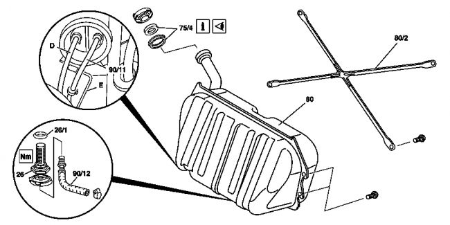
The fuel tank (80) is located in the trunk above the rear axle. The fuel tank (80) is made of sheet steel.
The fuel is drawn through the fuel strainer (26) in the fuel inlet hose (90/12). The fuel flows back along the return flow hose (90/11). The vent line (D) runs to the activated charcoal canister (in some cases with vent valve).
Fuel reserve
The 88 liter tank uses 11 liters as a reserve. The 78 liter tank uses 10 liters as a reserve.
The reserve is what is left when the needle is pointed all the way down to the bottom of the yellow area and the fuel warning light comes on. Hence, the fuel gauge in the instrument cluster shows the fuel level minus the reserve volume.
Splash bowl
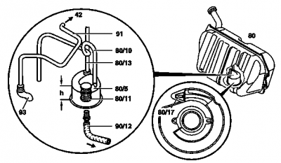
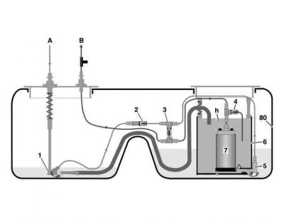
The swirl pot is mounted in the fuel tank. The task of the splash bowl is supplying the engine with fuel in the event of a low fuel level in the fuel tank and during lengthy cornering.
The fuel return flow stream flows out of the return flow nozzle (80/17) into the splash bolw at a high velocity when the fuel pump is operated. As a result, the fuel around the return flow nozzle (80/17) is also entrained and carried into the splash bowl.
Fuel level sensor
|
|
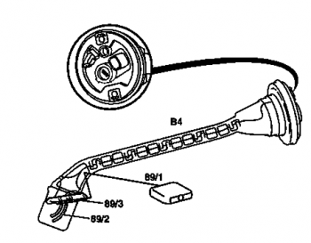
The fuel level indicator sensor (also known as fuel gauge) is installed in the fuel tank via a bayonet latch.
The task of the sensor is determining the fuel level in the fuel tank. The fuel level sensor (B4) is a lever-type sensor with sliding contacts (potentiometer).
The resistance of the fuel gage sensor (B4) is analyzed in the electronics of the fuel gage. Example model 208: Low resistance = Fuel tank empty, High resistance = Fuel tank full. In the event of a open circuit the fuel gauge in the instrument cluster indicates empty. The fuel reserve warning lamp (A1e4) does not light up.
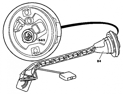
Fuel tank pressure sensor (version USA)
|
Shown on model 210:
|
The fuel tank pressure sensor is built into the hausing of the fuel gauge.
The task for the fuel tank pressure sensor is detecting the internal pressure of the fuel tank for the leak test of the fuel system.
The output signal depends on the pressure inside the tank and is transmitted to the engine control unit.
Remove/install fuel tank

|
Shown on fuel tank model 220 with option code 282 (SKI-BAG) or 308 (REFRIGERATOR IN REAR):
|
- Drain fuel tank (80). Pay attention to fuel quantity.
- Remove trim panel in trunk
- With option code 282 (SKI-BAG) or 308 (REFRIGERATOR IN REAR): Remove rear wall of fuel tank (80/1)
- With option code 282 (SKI-BAG) or 308 (REFRIGERATOR IN REAR): Detach lower mounting rails (80/23) of fuel tank rear wall (80/1) from trunk floor. Do not detach upper mounting rails (80/23) at rear shelf.
- With option code 282 (SKI-BAG) or 308 (REFRIGERATOR IN REAR): Take spare tire out of spare tire well
- Without option code 282 (SKI-BAG) or 308 (REFRIGERATOR IN REAR): Detach mounting struts (80/2) of fuel tank (80)
- Raise vehicle
- Vehicles with gasoline engine: Detach fuel hose on the suction side with connection fitting (90/12), fuel return hose (90/11), and fuel tank - activated charcoal canister line (gasoline engine). Do not damage fuel filter - fuel tank degassing line (gasoline engine) (E). Collect remaining fuel, seal connections.
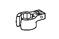
- Vehicles with diesel engine: Detach fuel hose on the suction side connection fitting (90/12), fuel return hose (90/11) and vent line (76/1). Collect remaining fuel, seal connections. Box wrench bit W000589710300.
- Take out fuel tank (80). Inspect whether cup seals (75/4) can be re-used.
- Check sound deadening mat for damage
- Remove fuel strainer (26). Clean and check for re-usability. The splash bowl in the fuel tank is secured against turning with 2 pins. It is attached together with the fuel strainer (26).
- Replace O-ring (26/1). Installation: Oil to facilitate installation.
- Install in the reverse order
Torque specifications:
- Fuel strainer in fuel tank: 40 Nm
- Fuel hose with connection fitting on fuel strainer: 30 Nm
