Uncategorized files
Jump to navigation
Jump to search
Showing below up to 50 results in range #1 to #50.
-
003 W220 Remove Ash Tray Torx Screws.JPG 1,205 × 789; 147 KB
-
004 W220 Remove Ash Tray.JPG 1,392 × 813; 198 KB
-
005 W220 Remove ACC Pushbutton Control Module.JPG 1,346 × 811; 149 KB
-
006 W220 ACC Pushbutton Control Module Housing.JPG 1,209 × 636; 109 KB
-
007 W220 ACC Pushbutton Control Module.JPG 1,089 × 487; 81 KB
-
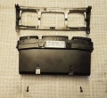
008 W220 ACC Pushbutton Control Module with Front Panel Removed.JPG 762 × 698; 119 KB
-
010 OEM COMAND Removed from W220.jpg 500 × 375; 35 KB
-
011 W220 ACC Pushbutton Control Module Separated.JPG 1,075 × 655; 157 KB
-
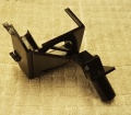
012 W220 ACC Pushbutton Control Module Aspirator Sub Module.JPG 460 × 418; 28 KB
-
013 W220 ACC Pushbutton Control Module Showing Five Tabs.JPG 624 × 351; 45 KB
-
014 W220 ACC Pushbutton Control Module Aspirator Housing Removed.JPG 681 × 596; 71 KB
-
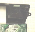
015 W220 ACC Pushbutton Control Module RH Small PCB.JPG 603 × 378; 49 KB
-
016 W220 ACC Pushbutton Control Module Thermistor on RH Small PCB.JPG 1,110 × 821; 149 KB
-
01 MFD Hidden Menu UB Engine Off.JPG 998 × 517; 53 KB
-
020 Replacement Erisin COMAND with modification brackets.jpg 500 × 375; 30 KB
-
02 MFD Hidden Menu DC W220MJ03 Engine Off.JPG 985 × 444; 57 KB
-
030 OEM COMAND Bracket Modifications.jpg 500 × 375; 39 KB
-
03 MFD Hidden Menu ESP DYNAMOMETER TEST Engine Off.JPG 1,029 × 452; 53 KB
-
040 Replacement Erisin Head Unit in W220.jpg 500 × 375; 32 KB
-
04 MFD Hidden Menu WIA-TYPE Engine Off.JPG 1,034 × 462; 56 KB
-
05 MFD Hidden Menu CONFIRMATION Engine Off.JPG 1,024 × 477; 56 KB
-
06 MFD Hidden Menu UB Engine On.JPG 1,037 × 462; 63 KB
-
10A Fuse Under Test.JPG 666 × 387; 47 KB
-
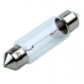
12V-5W bulb 36mm.jpg 500 × 500; 14 KB
-
12V USB Charge Volt Temp Adapter.JPG 417 × 412; 35 KB
-
13312.jpg 497 × 738; 141 KB
-
14mm-hex-socket-bit-1-2.jpg 720 × 480; 17 KB
-
1 W220 Using SDS get to the 211 Section.jpg 800 × 600; 41 KB
-
20200317 Access allowed, features enabled.JPG 538 × 300; 20 KB
-
20200317 Access already allowed.JPG 528 × 289; 20 KB
-
20200317 Bandende, kein ART (Tempomat aktiv).JPG 533 × 326; 31 KB
-
20200317 Coding has been read.JPG 539 × 324; 20 KB
-
20200317 Communication error 8.561.6067.JPG 530 × 287; 21 KB
-
20200317 Control unit adaptations.JPG 528 × 318; 25 KB
-
20200317 Control unit unlocked.JPG 536 × 287; 44 KB
-
20200317 DTR Control module has been successfully initialized.JPG 525 × 313; 25 KB
-
20200317 Implizite Kodierung ME28 F3-Stand.JPG 537 × 320; 28 KB
-
20200317 Is the coding to be transferred to the new control unit.JPG 539 × 310; 21 KB
-
20200317 SPEEDTRONIC present.JPG 533 × 178; 21 KB
-
20200317 The coding has been carried out.JPG 537 × 321; 21 KB
-
20200317 The coding is being read, please wait.JPG 537 × 310; 18 KB
-
20200319 DTR Network.JPG 1,016 × 650; 94 KB
-
202589004300 removal and installation tool.png 205 × 136; 3 KB
-
220067cc 10.jpg 640 × 480; 23 KB
-
220067cc 5.jpg 640 × 480; 23 KB


