Auxiliary battery: Difference between revisions
(Created page with "This page shows how to install auxiliary battery in W220. == Battery == For auxiliary battery it is better to not use starter battery (e.g. most automotive batteries), but a...") |
m (Pokseva moved page Auxiliary Battery to Auxiliary battery) |
||
| (3 intermediate revisions by the same user not shown) | |||
| Line 1: | Line 1: | ||
This page shows how to install auxiliary battery | This page shows how to install auxiliary battery and connect it to the charging system. | ||
Auxiliary battery is useful to power a coolbox/fridge or set up a 24/7 surveillance system | |||
without worrying about the starter battery being drained while the engine is not running. | |||
== Battery == | == Battery == | ||
For auxiliary battery it is better to not use starter battery (e.g. most automotive batteries), | For an auxiliary battery it is better to not use a starter battery (e.g. most automotive batteries), | ||
but a [https://en.wikipedia.org/wiki/Deep_cycle_battery deep-cycle] battery that is designed to be regularly deeply discharged using most of its capacity. | but a [https://en.wikipedia.org/wiki/Deep_cycle_battery deep-cycle] battery that is designed to be regularly deeply discharged using most of its capacity. | ||
| Line 19: | Line 21: | ||
== Installation == | == Installation == | ||
Battery fits tight in the left side of the trunk. For better fit wrap it | Battery fits tight in the left side of the trunk. For a better fit, wrap around it some solid rubber sheets. | ||
To put back the electronics bracket, it has to be cut below the navigation device level. | To put back the electronics bracket, it has to be cut below the navigation device level. | ||
[[MOST Audio Gateway|Audio gateway]] which was below the [[MOST Navigation|navigation unit]] can be attached to the navigation unit with cable ties as shown in the picture. | [[MOST Audio Gateway|Audio gateway]] which was below the [[MOST Navigation|navigation unit]] can be attached to the navigation unit with cable ties as shown in the picture. | ||
If [[MOST CD Changer|CD Changer]] is used, the space for it has to be found somewhere else. | If [[MOST CD Changer|CD Changer]] is used, the space for it has to be found somewhere else. | ||
Since the lower of | Since the lower part of electronics bracket is cut off, the bracket now is attached only by 2 screws instead of 3. | ||
screws instead of 3 | However, the installation is pretty tight anyway and unless the W220 is thrown on its roof the battery will not move from its place. | ||
Note that since the left side of the trunk is not square, | |||
two outer corners of the the battery will deform the chassis a bit (as can be seen in the picture below). | |||
{| | {| | ||
| Line 34: | Line 38: | ||
== Charging == | == Charging == | ||
We want the auxiliary battery to be isolated from the main circuit when the car is off (to not drain the auxiliary battery and vice versa), | We want the auxiliary battery to be isolated from the main circuit when the car is off (to not drain the auxiliary battery and vice versa), | ||
while connecting to the main circuit when the car is running so that alternator would charge both - the starter battery and the auxiliary battery. | |||
To do this automatically the starter battery's positive terminal and auxiliary battery's positive terminals must be connected together (using wires at least 3mm in thickness) by high current (200A) relay (EUR 10). The negative terminal of auxiliary battery can be permanently attached to the chassis. | To do this automatically, the starter battery's positive terminal and auxiliary battery's positive terminals must be connected together (using wires at least 3mm in thickness) by high current (200A) relay (EUR 10). The negative terminal of auxiliary battery can be permanently attached to the chassis. | ||
The relay should be activated by positive 12-volt wire from alternator's D+ terminal (warning lamp wire). | The relay should be activated by positive 12-volt wire from alternator's D+ terminal (warning lamp wire). | ||
This will make sure that auxiliary battery is connected to the main circuit only when the alternator is already producing the output. | This will make sure that auxiliary battery is connected to the main circuit only when the alternator is already producing the output. | ||
The optimal place to install the relay is to put it under the rear seat and attach it to the electronics bracket. | The optimal place to install the relay is to put it under the rear seat and attach it to the electronics bracket. | ||
The wire from engine bay can be passed to right footwell through the right fuse box and then to the rear seat | The wire from engine bay can be passed to right footwell through the right fuse box and then to the rear seat (consult [[Rear view camera#Wiring|rear view camera wiring]] guide). | ||
{| | {| | ||
| Line 49: | Line 53: | ||
== Original Auxiliary Battery == | == Original Auxiliary Battery == | ||
<!-- http://www.benzworld.org/forums/w220-s-class/1520174-how-many-batteries-do-we-have-2.html --> | <!-- http://www.benzworld.org/forums/w220-s-class/1520174-how-many-batteries-do-we-have-2.html --> | ||
There is retrofitting option for a second battery fitted on the right-hand side of the trunk above the existing battery as shown in WIS/ASRA under document AN54.10-P-0002I. This requires a new battery holder, circuit breaker and new modified trunk paneling for the right-hand side. The circuit breaker allows to manually switch to the auxiliary battery when required. | |||
[[File:W220_additional_battery.jpg|600px]] | |||
* G1/1 - Additional battery | |||
=== Retrofit additional battery=== | |||
<!-- AN54.10-P-0002I --> | |||
Steps: | |||
# Remove battery | |||
# Remove trim of trunk floor and right side paneling | |||
# Remove ground line | |||
# Remove rear bumper | |||
# Remove inner fender from rear fender onthe passenger side | |||
# [[#Prepare to retrofit battery frame | Prepare retrofit of battery frame]] | |||
# [[#Cutting out paneling in trunk | Cut out trim in luggage compartment]] | |||
# Install trim panel in luggage compartment right side paneling | |||
# Install battery (G1) | |||
# [[#Retrofit circuit breaker | Retrofit circuit breaker adapter on positive battery terminal]] | |||
# Install additional battery (G1/1). Fix additional battery in place with battery bracket and bolts M8 x 16 on battery frame. | |||
# Connect positive line of additional battery (G1/1) | |||
# Connect ground line of additional battery (G1/1) | |||
# Switch on circuit breaker | |||
# Install trim panel in luggage compartment. At the customer request cut out the removed part in the area of the battery frame. | |||
# Install battery lining | |||
# Install rear bumper | |||
# Install inner fender in rear fender | |||
# Read out fault memory and erase using STAR Diagnosis tool. | |||
{| class="wikitable" | |||
! Part No. | |||
! Designation | |||
! Quantity | |||
|+Parts needed | |||
|- | |||
|HKW220820L023 | |||
|Battery frame | |||
|1 | |||
|- | |||
|HKW078022A008 | |||
|Battery bracket | |||
|1 | |||
|- | |||
|HKW220821L004 | |||
|Bracket for additional parts | |||
|1 | |||
|- | |||
|HKW220690L000 | |||
|Battery cover | |||
|1 | |||
|- | |||
|A2204400430 | |||
|Positive line (additional battery on 1st battery) | |||
|1 | |||
|- | |||
|A2205400041 | |||
|Ground line (additional battery and 1st battery) | |||
|2 | |||
|- | |||
|A2205400141 | |||
|Ground line (circuit breaker to body) | |||
|1 | |||
|- | |||
|A0005410072 | |||
|Nut (adapter on battery positive pole) | |||
|1 | |||
|- | |||
|A0015460944 | |||
|Battery clamp | |||
|1 | |||
|- | |||
|A0005457608 | |||
|Circuit breaker | |||
|1 | |||
|- | |||
|N910105006033 | |||
|Bolt M6 x 20 | |||
|3 | |||
|- | |||
|N910105006002 | |||
|Bolt M6 x 12 | |||
|2 | |||
|- | |||
|N910105008041 | |||
|Screw M8 x 16 | |||
|2 | |||
|- | |||
|N910143006001 | |||
|Screw M6 x 16 | |||
|4 | |||
|- | |||
|N913023006001 | |||
|Nut M6 | |||
|8 | |||
|- | |||
|A0039941745 | |||
|Box nut M6 | |||
|1 | |||
|- | |||
|A0055411001 | |||
|Absorbent glass mat battery | |||
|2 | |||
|- | |||
|A0029972486 | |||
|Plug | |||
|1 | |||
|- | |||
|A0009903872 | |||
|Distributor fitting | |||
|2 | |||
|- | |||
|HKW220680L017 | |||
|Trunk floor paneling | |||
|1 | |||
|} | |||
===Prepare to retrofit battery frame=== | |||
<!--AN54.10-P-0002-01I --> | |||
{| | |||
|[[File:W220_additional_battery_frame.jpg]] | |||
| | |||
* 1 - Battery frame | |||
* 1a - Bracket | |||
* 2 - Drill holes | |||
* 3 - Drill holes | |||
* 4 - Drill hole | |||
|} | |||
# Position battery frame (1) in trunk. | |||
# Mark holes to be drilled (2, 3, 4). | |||
# Remove battery frame. | |||
# Drill holes (2, 3, 4) with 6.5 mm dia. bit. | |||
# Remove insulating mats in area of contact surface of battery frame. | |||
# Remove U-guard from rear of drill holes (2, 3). | |||
# Insert M6 x 16 screws in rear wheelhouse to trunk and weld on. | |||
# Insert M6 x 16 screws in trunk floor to trunk and weld on. | |||
# Apply corrosion protection to hole (4). | |||
# Position M6 box nut on hole (4). | |||
# Vacuum clean trunk. | |||
===Cutting out paneling in trunk=== | |||
<!-- AN68.30-P-0002-01I --> | |||
{| | |||
|[[File:W220_cutting_out_paneling_in_trunk.jpg|600px]] | |||
| | |||
* 6 - Cutout for battery frame | |||
* 7 - Cutout for battery frame | |||
* 8 - Cutout for positive lead | |||
* 9 - Cut for battery paneling | |||
* 10 - Battery paneling | |||
|} | |||
# Mark right side paneling (5) in area of battery frame (6, 7) and positive lead (8) and cut out. | |||
# Insert battery paneling (10). | |||
# Mark cuts (9) and cut in. | |||
# Remove battery paneling (10) | |||
===Retrofit circuit breaker=== | |||
<!-- AN54.10-P-0002-03I --> | |||
{| | |||
|[[File:W220_retrofit_circuit_breaker_1.jpg]] | |||
|[[File:W220_retrofit_circuit_breaker_2.jpg]] | |||
|[[File:W220_retrofit_circuit_breaker_3.jpg]] | |||
|} | |||
{| | |||
|[[File:W220_retrofit_circuit_breaker_4.jpg]] | |||
|[[File:W220_retrofit_circuit_breaker_5.jpg]] | |||
|} | |||
# Mount positive line (13) on battery clamp (14). | |||
# Screw on adapter (15). Adapter on battery positive pole. | |||
# Connect positive line (13) to 1st battery (G1). | |||
# Fasten circuit breaker (16) with bolts M6 x 20 and nuts M6 to bracket for additional parts (17). | |||
# Mount ground line for additional battery (18) and ground line for 1st battery (19) on a contact on the circuit breaker (16) and screw on with nut. (17) is a bracket for additional parts | |||
# Connect ground line (20) to battery ground (W10). | |||
# Mount ground line (20) on free contact on circuit breaker (16) and screw on with nut. | |||
# Connect ground line (19) from circuit breaker (16) to 1st battery. | |||
# Install battery frame (1). | |||
# Install bracket for additional parts (17) with circuit breaker (16). | |||
Latest revision as of 17:16, 28 July 2016
This page shows how to install auxiliary battery and connect it to the charging system. Auxiliary battery is useful to power a coolbox/fridge or set up a 24/7 surveillance system without worrying about the starter battery being drained while the engine is not running.
Battery
For an auxiliary battery it is better to not use a starter battery (e.g. most automotive batteries), but a deep-cycle battery that is designed to be regularly deeply discharged using most of its capacity.
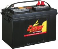
Crown 27DC115 (EUR 200) is battery that perfectly fits in the left side of W220 trunk.
Specification:
|
 |
Installation
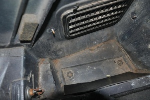
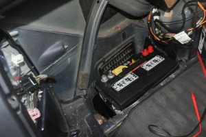
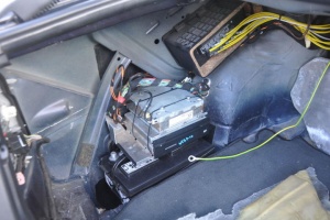
Battery fits tight in the left side of the trunk. For a better fit, wrap around it some solid rubber sheets. To put back the electronics bracket, it has to be cut below the navigation device level. Audio gateway which was below the navigation unit can be attached to the navigation unit with cable ties as shown in the picture. If CD Changer is used, the space for it has to be found somewhere else. Since the lower part of electronics bracket is cut off, the bracket now is attached only by 2 screws instead of 3. However, the installation is pretty tight anyway and unless the W220 is thrown on its roof the battery will not move from its place. Note that since the left side of the trunk is not square, two outer corners of the the battery will deform the chassis a bit (as can be seen in the picture below).
 |
 |
 |
Charging
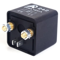
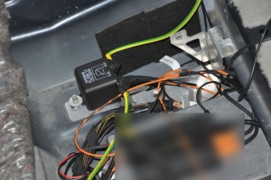
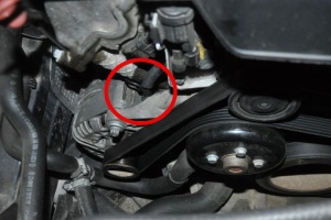
We want the auxiliary battery to be isolated from the main circuit when the car is off (to not drain the auxiliary battery and vice versa), while connecting to the main circuit when the car is running so that alternator would charge both - the starter battery and the auxiliary battery. To do this automatically, the starter battery's positive terminal and auxiliary battery's positive terminals must be connected together (using wires at least 3mm in thickness) by high current (200A) relay (EUR 10). The negative terminal of auxiliary battery can be permanently attached to the chassis. The relay should be activated by positive 12-volt wire from alternator's D+ terminal (warning lamp wire). This will make sure that auxiliary battery is connected to the main circuit only when the alternator is already producing the output. The optimal place to install the relay is to put it under the rear seat and attach it to the electronics bracket. The wire from engine bay can be passed to right footwell through the right fuse box and then to the rear seat (consult rear view camera wiring guide).
 |
 |
 |
Original Auxiliary Battery
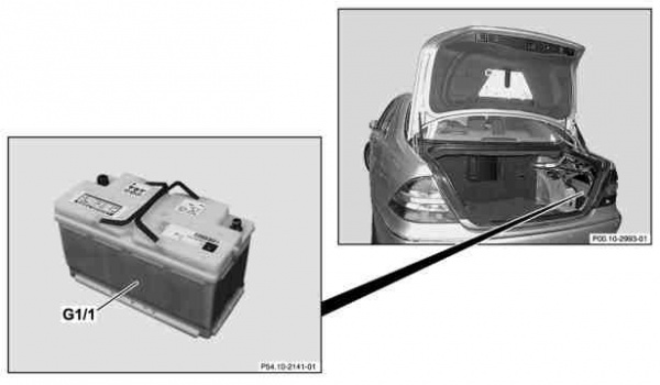
There is retrofitting option for a second battery fitted on the right-hand side of the trunk above the existing battery as shown in WIS/ASRA under document AN54.10-P-0002I. This requires a new battery holder, circuit breaker and new modified trunk paneling for the right-hand side. The circuit breaker allows to manually switch to the auxiliary battery when required.
- G1/1 - Additional battery
Retrofit additional battery
Steps:
- Remove battery
- Remove trim of trunk floor and right side paneling
- Remove ground line
- Remove rear bumper
- Remove inner fender from rear fender onthe passenger side
- Prepare retrofit of battery frame
- Cut out trim in luggage compartment
- Install trim panel in luggage compartment right side paneling
- Install battery (G1)
- Retrofit circuit breaker adapter on positive battery terminal
- Install additional battery (G1/1). Fix additional battery in place with battery bracket and bolts M8 x 16 on battery frame.
- Connect positive line of additional battery (G1/1)
- Connect ground line of additional battery (G1/1)
- Switch on circuit breaker
- Install trim panel in luggage compartment. At the customer request cut out the removed part in the area of the battery frame.
- Install battery lining
- Install rear bumper
- Install inner fender in rear fender
- Read out fault memory and erase using STAR Diagnosis tool.
| Part No. | Designation | Quantity |
|---|---|---|
| HKW220820L023 | Battery frame | 1 |
| HKW078022A008 | Battery bracket | 1 |
| HKW220821L004 | Bracket for additional parts | 1 |
| HKW220690L000 | Battery cover | 1 |
| A2204400430 | Positive line (additional battery on 1st battery) | 1 |
| A2205400041 | Ground line (additional battery and 1st battery) | 2 |
| A2205400141 | Ground line (circuit breaker to body) | 1 |
| A0005410072 | Nut (adapter on battery positive pole) | 1 |
| A0015460944 | Battery clamp | 1 |
| A0005457608 | Circuit breaker | 1 |
| N910105006033 | Bolt M6 x 20 | 3 |
| N910105006002 | Bolt M6 x 12 | 2 |
| N910105008041 | Screw M8 x 16 | 2 |
| N910143006001 | Screw M6 x 16 | 4 |
| N913023006001 | Nut M6 | 8 |
| A0039941745 | Box nut M6 | 1 |
| A0055411001 | Absorbent glass mat battery | 2 |
| A0029972486 | Plug | 1 |
| A0009903872 | Distributor fitting | 2 |
| HKW220680L017 | Trunk floor paneling | 1 |
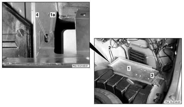
Prepare to retrofit battery frame
|
|
- Position battery frame (1) in trunk.
- Mark holes to be drilled (2, 3, 4).
- Remove battery frame.
- Drill holes (2, 3, 4) with 6.5 mm dia. bit.
- Remove insulating mats in area of contact surface of battery frame.
- Remove U-guard from rear of drill holes (2, 3).
- Insert M6 x 16 screws in rear wheelhouse to trunk and weld on.
- Insert M6 x 16 screws in trunk floor to trunk and weld on.
- Apply corrosion protection to hole (4).
- Position M6 box nut on hole (4).
- Vacuum clean trunk.
Cutting out paneling in trunk
|
|
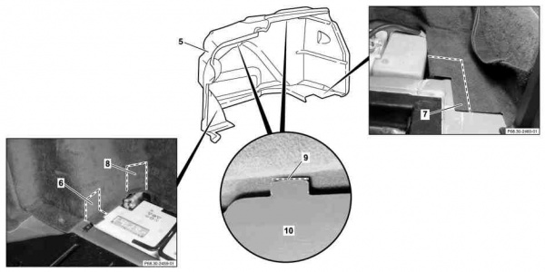
- Mark right side paneling (5) in area of battery frame (6, 7) and positive lead (8) and cut out.
- Insert battery paneling (10).
- Mark cuts (9) and cut in.
- Remove battery paneling (10)
Retrofit circuit breaker
|
|
|
|
|
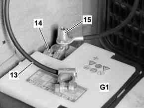
- Mount positive line (13) on battery clamp (14).
- Screw on adapter (15). Adapter on battery positive pole.
- Connect positive line (13) to 1st battery (G1).
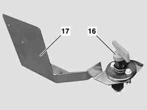
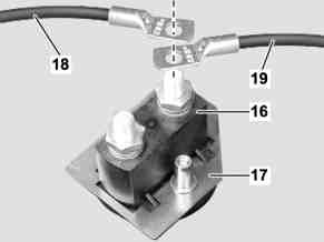
- Fasten circuit breaker (16) with bolts M6 x 20 and nuts M6 to bracket for additional parts (17).
- Mount ground line for additional battery (18) and ground line for 1st battery (19) on a contact on the circuit breaker (16) and screw on with nut. (17) is a bracket for additional parts
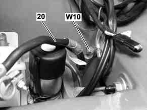
- Connect ground line (20) to battery ground (W10).
- Mount ground line (20) on free contact on circuit breaker (16) and screw on with nut.
- Connect ground line (19) from circuit breaker (16) to 1st battery.
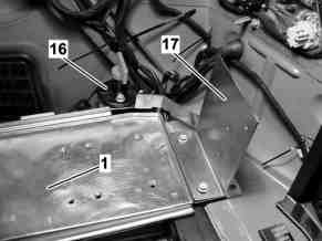
- Install battery frame (1).
- Install bracket for additional parts (17) with circuit breaker (16).
