WIS 91.16 Head-rest/Restraint: Difference between revisions
Ricebubbles (talk | contribs) m (→Description - Rear Head-rest/Restraint: Typo) |
Ricebubbles (talk | contribs) (→DIY Remove Mechanism - Rear Head-rest/Restraint: Added more detail for removing rear head rest and rearranged for better clarity) |
||
| (2 intermediate revisions by the same user not shown) | |||
| Line 22: | Line 22: | ||
The rear head-rests/restraints automatically move into the up position whenever anyone sits in a rear seat and fastens their seat belt. All three head-rests may be lowered by momentarily pressing the button on the dash. Holding this button pressed will also raise the two outer head-rests. The centre head-rest must be raised manually. | The rear head-rests/restraints automatically move into the up position whenever anyone sits in a rear seat and fastens their seat belt. All three head-rests may be lowered by momentarily pressing the button on the dash. Holding this button pressed will also raise the two outer head-rests. The centre head-rest must be raised manually. | ||
* When the head rest button on the dash is pressed for greater than 2-3 seconds, the PSE Pump provides positive air pressure to the Rear Head-rest/Restraint Actuators and an electrical signal is provided for a few seconds to the valve inside the Rear Head-rest/Restraint Actuators. The positive pressure pushes the piston inside the actuators to the fully extended position. While the valve is actuated, the positive pressure is transferred through the actuators to Air Bladders in each unit which causes the Head-rest/Restraints to fully raise and lock into position. | * When the head rest button on the dash is pressed for greater than 2-3 seconds, the PSE Pump provides positive air pressure to the Rear Head-rest/Restraint Actuators and an electrical signal is provided for a few seconds to the valve inside the Rear Head-rest/Restraint Actuators. The positive pressure pushes the piston inside the actuators to the fully extended position. While the valve is actuated, the positive pressure is transferred through the actuators to Air Bladders in each unit which causes the Head-rest/Restraints to fully raise and lock into position. | ||
The Air Bladder is a clever device in the shape of a butterfly and when inflated applies torque to the head-rest axle and slowly and quietly raises the head-rest. In the fully raised position a spring loaded mechanism locks the head-rest/restraint into position. | |||
'''Closeup of Rear Head-rest/Restraint Bladder''' | |||
[[File:Closeup of Rear Head-rest Restraint Bladder.jpg|300px|center]] | |||
Once fully raised and the head-rest/restraint is locked into position, it cannot be lowered manually. To lower each or all head-rest/restraints requires a momentary press on the dashboard button which sends an electrical signal to the solenoid actuator and the PSE Pump. | |||
==Part Numbers - Rear Head-rest/Restraint== | ==Part Numbers - Rear Head-rest/Restraint== | ||
| Line 49: | Line 55: | ||
==DIY Remove Mechanism - Rear Head-rest/Restraint== | ==DIY Remove Mechanism - Rear Head-rest/Restraint== | ||
The procedure to remove a head rest mechanism is very similar for all three head rests. | |||
The | |||
''' | ===Gain Access to Mechanism - Rear Head-rest/Restraint=== | ||
The | '''1. Remove Rear Seat Squab/Cushion''' | ||
The next step is to remove the rear seat squab. TIP: Move the seat to the maximum forward position. Reach underneath where there are two springs (marked 4 in the next Figure) which must be pressed outwards to release the seat. | |||
[[File:Remove Rear Seat Squab Cushion.jpg|500px|center]] | [[File:Remove Rear Seat Squab Cushion.jpg|500px|center]] | ||
[[File:Press Two Grey Levers to Remove Rear Seat Squab Cushion.jpg|500px|center]] | [[File:Press Two Grey Levers to Remove Rear Seat Squab Cushion.jpg|500px|center]] | ||
| Line 71: | Line 65: | ||
[[File:Rear Seat Squab Cushion Frame.jpg|500px|center]] | [[File:Rear Seat Squab Cushion Frame.jpg|500px|center]] | ||
''' | '''2. Remove Two Lower Mounting Bolts for the Rear Seat Back-rest''' | ||
Once the seat squab/cushion is out of the way it exposes the two lower mounting bolts for the Rear Seat Back-rest. Nickel plated (silver) in the next photo. Remove both of these bolts (10mm Torx). | Once the seat squab/cushion is out of the way it exposes the two lower mounting bolts for the Rear Seat Back-rest. Nickel plated (silver) in the next photo. Remove both of these bolts (10mm Torx). | ||
[[File:Two Lower Mounting Bolts For The Rear Seat Back-rest.jpg|500px|center]] | [[File:Two Lower Mounting Bolts For The Rear Seat Back-rest.jpg|500px|center]] | ||
''' | '''3. Remove Rear Upper Chrome Kick Plate''' | ||
The upper chrome kick plate can be prised off with plastic or wooden wedges. | The upper chrome kick plate can be prised off with plastic or wooden wedges. | ||
[[File:Remove Rear Upper Chrome Kick Plate.jpg|400px|center]] | [[File:Remove Rear Upper Chrome Kick Plate.jpg|400px|center]] | ||
''' | '''4. Remove Rear Seat Lumbar Adjustment Control and Trim''' | ||
Next remove the Rear Seat Lumbar Adjustment Control and associated Trim. The control can be prised out with a sharp plastic wedge and the two airlines disconnected. | Next remove the Rear Seat Lumbar Adjustment Control and associated Trim. The control can be prised out with a sharp plastic wedge and the two airlines disconnected. | ||
[[File:Remove Rear Seat Lumbar Adjustment Control and Trim.jpg|400px|center]] | [[File:Remove Rear Seat Lumbar Adjustment Control and Trim.jpg|400px|center]] | ||
''' | '''5. Remove Trim Between Rear Seat Backrest and Door Frame''' | ||
By carefully prising and pulling, the leather trim between the rear seat backrest and the door frame can be removed. This exposes the first of the two upper mounting bolts for the rear seat back-rest. Remove this bolt. | By carefully prising and pulling, the leather trim between the rear seat backrest and the door frame can be removed. This exposes the first of the two upper mounting bolts for the rear seat back-rest. Remove this bolt. | ||
[[File:First of the Two Upper Mounting Bolts for the Rear Seat Back-rest.jpg|400px|center]] | [[File:First of the Two Upper Mounting Bolts for the Rear Seat Back-rest.jpg|400px|center]] | ||
''' | '''6. Remove Centre Console Upper Back-rest''' | ||
Next remove the Centre Console Upper Back-rest. There are two plastic clips about a third of the way down on both sides. These must be depressed with two fingers to release. | Next remove the Centre Console Upper Back-rest. There are two plastic clips about a third of the way down on both sides. These must be depressed with two fingers to release. | ||
[[File:Rear View of Plastic Clip on Centre Console Upper Back-rest.jpg|400px|center]] | [[File:Rear View of Plastic Clip on Centre Console Upper Back-rest.jpg|400px|center]] | ||
The Centre Console Upper Back-rest can then be pulled out with an upwards movement. | The Centre Console Upper Back-rest can then be pulled out with an upwards movement. | ||
''' | '''7. Remove Centre Upper Mounting Bolts''' | ||
With the Centre Console Upper Back-rest out of the way it exposes the two centre upper mounting bolts for both Left and Right Rear Seat Backs. | With the Centre Console Upper Back-rest out of the way it exposes the two centre upper mounting bolts for both Left and Right Rear Seat Backs. | ||
| Line 98: | Line 92: | ||
[[File:Centre Upper Mounting Bolts for Left and Right Rear Seat Backs.jpg|400px|center]] | [[File:Centre Upper Mounting Bolts for Left and Right Rear Seat Backs.jpg|400px|center]] | ||
''' | '''8. Remove Rear Seat Back-rest''' | ||
The rear seat back-rest can now be removed with an upwards movement. It easily clears the raised head-rest which could not be lowered. The first time I did this repair I left the left head-rest in place. The second time, two years later, I had to remove all three head-rests so that I could raise the rear window shelf to remove the right head-rest mechanism. | The rear seat back-rest can now be removed with an upwards movement. It easily clears the raised head-rest which could not be lowered. The first time I did this repair I left the left head-rest in place. The second time, two years later, I had to remove all three head-rests so that I could raise the rear window shelf to remove the right head-rest mechanism. | ||
[[File:Rear Seat Back-rest Removed.jpg|400px|center]] | [[File:Rear Seat Back-rest Removed.jpg|400px|center]] | ||
''' | '''9. Lower the Plastic Lining''' | ||
When the corner of the plastic lining is lowered it reveals the Rear Head-rest/Restraint Actuator. | When the corner of the plastic lining is lowered it reveals the Rear Head-rest/Restraint Actuator. | ||
| Line 108: | Line 102: | ||
[[File:Faulty Rear Left Head-rest Restraint Actuator.jpg|400px|center]] | [[File:Faulty Rear Left Head-rest Restraint Actuator.jpg|400px|center]] | ||
''' | ===Identify Parts of Mechanism - Rear Head-rest/Restraint=== | ||
The Rear Left Head-rest/Restraint Actuator can be removed | '''1. Identification of Main Parts for Removing Rear Head Rest''' | ||
First study this diagram to understand the main parts securing a rear head rest mechanism in the car. | |||
[[File:W220 Rear Head Rest Removal 01.JPG|600px|center]] | |||
'''2. Raise Rear Head-Rest''' | |||
If the Head Rest is not already in the raised position, manually raise it. | |||
'''3. Remove Plastic Cover Around Head-Rest Chrome Arms''' | |||
The trick to removing the plastic cover around each head-rest/restraint arms is to use a flat head screw driver to gently prise up the front edge and then pull the cover upwards and towards the front of the car. | |||
[[File:Remove Three Rear Head-rest Restraints.jpg|400px|center]] | |||
'''4. Identify the Head-Rest Chrome Arms Retaining Clips''' | |||
Using a mirror, look closely at the holes and you will see small black plastic levers inside. They are positioned on the outer sides of each chrome arm. | |||
This view of the mechanism once removed, shows the black plastic levers (white arrows) which secure the head-rest/restraint arms in position. | |||
[[File:Rear Head-rest Restraint Black Plastic Securing Levers.jpg|400px|center]] | |||
'''5. Where to Apply Force for Removing Rear Head Rest''' | |||
[[File:W220 Rear Head Rest Removal 02.JPG|600px|center]] | |||
You need to push each retaining clip down about 0.5cm while pulling the headrest arm out towards the rear of the car. | |||
'''6. Direction of Applied Force for Removing Rear Head Rest''' | |||
Use a screw driver as a lever over the edge of the access hole to apply a downwards force on the retaining clip. | |||
Simultaneously apply another force by pulling the chrome arm in the removal direction (towards the rear of the car). TIP: If this is the first time the head rest has been removed, you may need to apply considerable force towards the rear of the car to break the arm free from its socket. A second long screw driver can help. | |||
[[File:W220 Rear Head Rest Removal 03.JPG|600px|center]] | |||
'''7. Removing Rear Head Rest Second Chrome Arm''' | |||
Having released one chrome arm use the same procedure to release the other side. TIP: You will need to hold the released side of the headrest out a little, while you release the arm on the other side. (Otherwise it will possibly click back into the locked position.) | |||
===Remove Mechanism - Rear Head-rest/Restraint=== | |||
The technique for removing the head rest mechanisms is slightly different for left and right sides. | |||
'''1. Remove Rear Left Head-rest/Restraint Mechanism ''' | |||
The Rear '''Left''' Head-rest/Restraint Actuator can only be removed after disconnecting the two air lines and the electrical connector. | |||
The grey pneumatic line connector is easily prised off from the front. | The grey pneumatic line connector is easily prised off from the front. | ||
| Line 115: | Line 145: | ||
The white pneumatic line connector is a challenge. It best removed by manipulating the mechanism to the left of the car to expose the white pneumatic line. Then prise off the connection with long nose pliers. | The white pneumatic line connector is a challenge. It best removed by manipulating the mechanism to the left of the car to expose the white pneumatic line. Then prise off the connection with long nose pliers. | ||
Manipulate the mechanism to expose the electrical connector and remove with long nose pliers. | '''2. Remove Rear Left Head-rest/Restraint Mounting Screws''' | ||
Remove the two rear screws and loosen the two top screws which don’t need to be completely removed. | |||
[[File:W220 Position of Torx Bolts for Rear Seat Head Restraint Mechanism.JPG|400px|center]] | |||
Manipulate the mechanism to expose the electrical connector and remove with long nose pliers. TIP: Be careful not to damage the connector as the plastic gets very brittle with age. | |||
Manipulate the mechanism so that the white bellows can be removed. | Manipulate the mechanism so that the white bellows can be removed. | ||
| Line 123: | Line 157: | ||
Often you will find that several plastic lugs holding the actuator together have broken and allowed the actuator to leak slightly as well as become dislodged. | Often you will find that several plastic lugs holding the actuator together have broken and allowed the actuator to leak slightly as well as become dislodged. | ||
''' | '''3. Remove Rear Right Head-rest/Restraint Mechanism ''' | ||
After removing the seats the Rear Right Head-rest/Restraint Mechanism is still not accessible until the rear window shelf is either removed or blocked up out of the way. | The Rear '''Right''' Head-rest/Restraint Mechanism is removed in a similar fashion to the left side. Use the steps for removing left head rest above. | ||
Later note: TIP: It is not necessary to remove the C-Pillar Trim or even block the Rear Window Shelf up out of the way as per paragraphs 3a, 4 and 5 following. The two screws adjacent to the child seat restraint mounting point can be removed through the hole above the child seat mounting point. | |||
'''3a. If the tip in paragraph 12 doesn't work then use these steps.''' After removing the seats the Rear '''Right''' Head-rest/Restraint Mechanism is still not accessible until the rear window shelf is either removed or blocked up out of the way. | |||
[[File:Rear Right Head-rest Restraint Mechanism.jpg|400px|center]] | [[File:Rear Right Head-rest Restraint Mechanism.jpg|400px|center]] | ||
''' | '''4. Remove the C-Pillar trim on both sides''' | ||
''' | '''5. Block the Rear Window Shelf up out of the way''' | ||
[[File:Rear Window Shelf blocked up out of the way.jpg|400px|center]] | [[File:Rear Window Shelf blocked up out of the way.jpg|400px|center]] | ||
''' | '''6. Remove Rear Right Head-rest/Restraint Mounting Screws''' | ||
Remove the two rear screws and loosen the two top screws which don’t need to be completely removed. | Remove the two rear screws and loosen the two top screws which don’t need to be completely removed. | ||
[[File:W220 Position of Torx Bolts for Rear Seat Head Restraint Mechanism.JPG|400px|center]] | [[File:W220 Position of Torx Bolts for Rear Seat Head Restraint Mechanism.JPG|400px|center]] | ||
| Line 142: | Line 180: | ||
[[File:Rear Right Head-rest Restraint Mechanism and Actuator.jpg|400px|center]] | [[File:Rear Right Head-rest Restraint Mechanism and Actuator.jpg|400px|center]] | ||
==DIY Reinstall Mechanism - Rear Head-rest/Restraint== | |||
Reinstallation is just a matter of reversing the dismantling procedure. It is a good idea to use some dielectric grease (also used on spark plug wires) to lubricate the pneumatic lines before reconnecting them. | Reinstallation is just a matter of reversing the dismantling procedure. It is a good idea to use some dielectric grease (also used on spark plug wires) to lubricate the pneumatic lines before reconnecting them. | ||
TIP: If you are remounting the new or repaired rear head-rest/restraint actuator (hockey puck) make sure that the slotted lever arm on the piston engages the pin on the head-rest mechanism. | |||
==DIY Repair Mechanism - Rear Head-rest/Restraint== | ==DIY Repair Mechanism - Rear Head-rest/Restraint== | ||
Latest revision as of 02:18, 21 August 2018
Rear Rear Head-rest/Restraint
Description - Rear Head-rest/Restraint
Automatic Rear Head-rest/Restraints are fitted on a 2003 update W220 S500L model with electric rear seats and lumbar adjustment in the back-rest.
The Automatic Rear Head-rest/Restraints consist of head rests which can be lowered to improve rear visibility and which automatically raise up and lock into position when the rear seat is occupied.
They can be raised manually by reaching over the seat and lifting them into position.
They can be raised remotely by using the head rest button on the dash board.
The actual head rest may be manually adjusted for angle to suit the occupant.
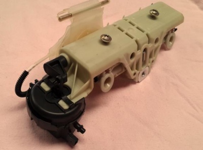
The rear head rest actuator (M-B calls the whole assembly a 'motor', comprises a mounting mechanism with bladder for raising the head rest and an solenoid actuator for releasing the head rest latch for lowering.
Left to right in the next photo: Bladder, solenoid release actuator and mounting mechanism.

Rear Left Head-rest Restraint Assembled.
Function - Rear Head-rest/Restraint
The rear head-rests/restraints automatically move into the up position whenever anyone sits in a rear seat and fastens their seat belt. All three head-rests may be lowered by momentarily pressing the button on the dash. Holding this button pressed will also raise the two outer head-rests. The centre head-rest must be raised manually.
- When the head rest button on the dash is pressed for greater than 2-3 seconds, the PSE Pump provides positive air pressure to the Rear Head-rest/Restraint Actuators and an electrical signal is provided for a few seconds to the valve inside the Rear Head-rest/Restraint Actuators. The positive pressure pushes the piston inside the actuators to the fully extended position. While the valve is actuated, the positive pressure is transferred through the actuators to Air Bladders in each unit which causes the Head-rest/Restraints to fully raise and lock into position.
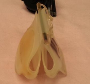
The Air Bladder is a clever device in the shape of a butterfly and when inflated applies torque to the head-rest axle and slowly and quietly raises the head-rest. In the fully raised position a spring loaded mechanism locks the head-rest/restraint into position. Closeup of Rear Head-rest/Restraint Bladder
Once fully raised and the head-rest/restraint is locked into position, it cannot be lowered manually. To lower each or all head-rest/restraints requires a momentary press on the dashboard button which sends an electrical signal to the solenoid actuator and the PSE Pump.
Part Numbers - Rear Head-rest/Restraint
The Rear Head-rest/Restraint Actuator usually has two part numbers stuck on it. The numbers are:
- Green label refers to the whole Head Rest Motor – Bucket Seats.
- Rear Left Head Rest Motor – Bucket Seats 220 970 09 25
- Rear Right Head Rest Motor – Bucket Seats 220 970 10 25
- White label refers to the solenoid actuator part only.
- Rear Left Head Rest solenoid actuator 220 800 04 75.
- Rear Right Head Rest solenoid actuator 220 800 04 75. Same as Rear Left Head Rest solenoid actuator.
Testing - Rear Head-rest/Restraint
Required function.
- All Rear Head-rest/Restraints can be raised manually.
- Both Left and Right Rear Head-rest/Restraints can be raised by pressing the button on the dash for greater than 2-3 seconds.
- Only the Left and Right Rear Head-rest/Restraints can be raised by fastening the associated rear seat belt.
- The Centre Rear Head Head-rest/Restraint can only be raised manually.
- All Rear Head-rest/Restraints can be lowered by momentarily pressing the button on the dash.
- All Rear Head-rest/Restraints cannot be lowered manually.
Issues - Rear Head-rest/Restraint
- The head-rests cannot be lowered manually. If they stick in the raised position they can obstruct the view out the rear window.
- Some of the procedure for removing the rear Head-rest/Restraint is rather tricky and is not explained in STAR XENTRY WIS. The author wasted a lot of time removing all the boot/trunk lining only to find that it is not possible to access the head-rest/restraint mechanism because of the fuel tank.
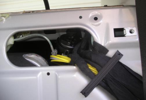
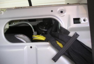
- The Rear Head-rest/Restraint solenoid actuator can easily come off the main part of the mechanism thus leaving the Rear Head-rest/Restraint in the raised position. The next photo shows a dislodged rear left head rest actuator.
- The Rear Head-rest/Restraint solenoid actuator often breaks in half as the securing lugs are rather weak.
DIY Remove Mechanism - Rear Head-rest/Restraint
The procedure to remove a head rest mechanism is very similar for all three head rests.
Gain Access to Mechanism - Rear Head-rest/Restraint
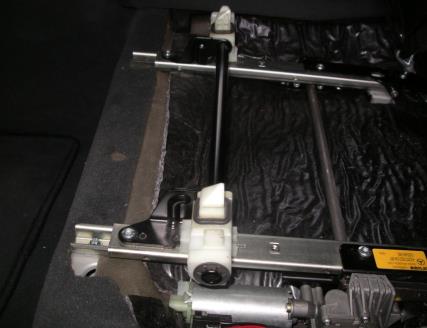
1. Remove Rear Seat Squab/Cushion The next step is to remove the rear seat squab. TIP: Move the seat to the maximum forward position. Reach underneath where there are two springs (marked 4 in the next Figure) which must be pressed outwards to release the seat.
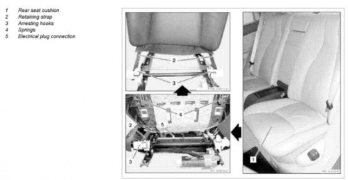
This exposes the Rear Seat Squab Cushion Frame. The two large white plastic objects are the points where the springs locate and hold the seat squab/cushion on the frame.
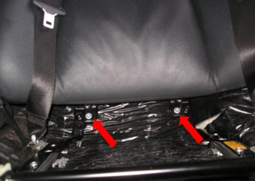
2. Remove Two Lower Mounting Bolts for the Rear Seat Back-rest Once the seat squab/cushion is out of the way it exposes the two lower mounting bolts for the Rear Seat Back-rest. Nickel plated (silver) in the next photo. Remove both of these bolts (10mm Torx).
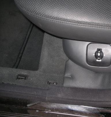
3. Remove Rear Upper Chrome Kick Plate The upper chrome kick plate can be prised off with plastic or wooden wedges.
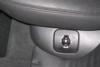
4. Remove Rear Seat Lumbar Adjustment Control and Trim Next remove the Rear Seat Lumbar Adjustment Control and associated Trim. The control can be prised out with a sharp plastic wedge and the two airlines disconnected.
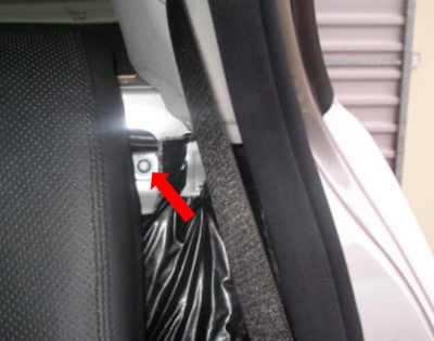
5. Remove Trim Between Rear Seat Backrest and Door Frame By carefully prising and pulling, the leather trim between the rear seat backrest and the door frame can be removed. This exposes the first of the two upper mounting bolts for the rear seat back-rest. Remove this bolt.
6. Remove Centre Console Upper Back-rest Next remove the Centre Console Upper Back-rest. There are two plastic clips about a third of the way down on both sides. These must be depressed with two fingers to release.
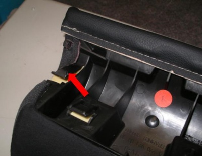
The Centre Console Upper Back-rest can then be pulled out with an upwards movement.
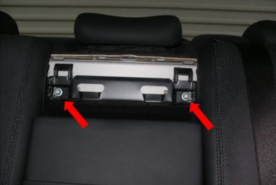
7. Remove Centre Upper Mounting Bolts With the Centre Console Upper Back-rest out of the way it exposes the two centre upper mounting bolts for both Left and Right Rear Seat Backs.
Remove centre upper mounting bolts for both Left and Right Rear Seat Backs.
8. Remove Rear Seat Back-rest The rear seat back-rest can now be removed with an upwards movement. It easily clears the raised head-rest which could not be lowered. The first time I did this repair I left the left head-rest in place. The second time, two years later, I had to remove all three head-rests so that I could raise the rear window shelf to remove the right head-rest mechanism.
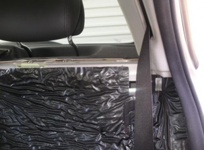
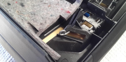
9. Lower the Plastic Lining When the corner of the plastic lining is lowered it reveals the Rear Head-rest/Restraint Actuator.
In the next photo the Rear Head-rest/Restraint Actuator can be seen dislodged from its correct position.
Identify Parts of Mechanism - Rear Head-rest/Restraint
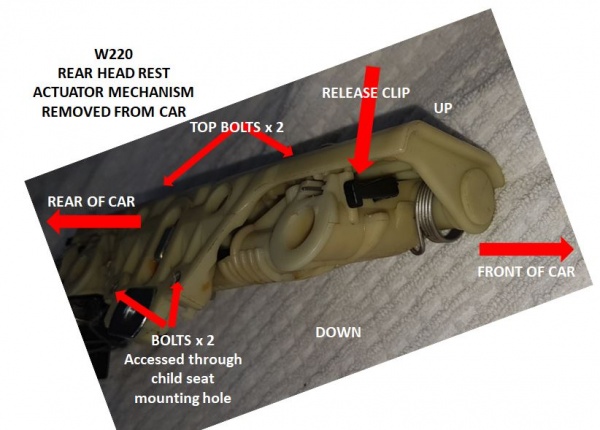
1. Identification of Main Parts for Removing Rear Head Rest First study this diagram to understand the main parts securing a rear head rest mechanism in the car.
2. Raise Rear Head-Rest If the Head Rest is not already in the raised position, manually raise it.
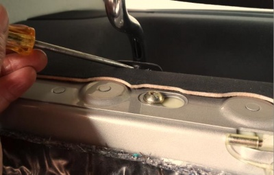
3. Remove Plastic Cover Around Head-Rest Chrome Arms The trick to removing the plastic cover around each head-rest/restraint arms is to use a flat head screw driver to gently prise up the front edge and then pull the cover upwards and towards the front of the car.
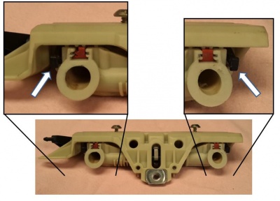
4. Identify the Head-Rest Chrome Arms Retaining Clips Using a mirror, look closely at the holes and you will see small black plastic levers inside. They are positioned on the outer sides of each chrome arm.
This view of the mechanism once removed, shows the black plastic levers (white arrows) which secure the head-rest/restraint arms in position.
5. Where to Apply Force for Removing Rear Head Rest
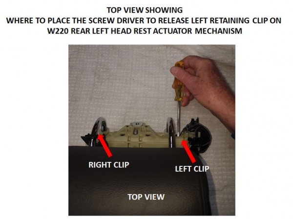
You need to push each retaining clip down about 0.5cm while pulling the headrest arm out towards the rear of the car.
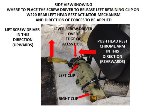
6. Direction of Applied Force for Removing Rear Head Rest Use a screw driver as a lever over the edge of the access hole to apply a downwards force on the retaining clip.
Simultaneously apply another force by pulling the chrome arm in the removal direction (towards the rear of the car). TIP: If this is the first time the head rest has been removed, you may need to apply considerable force towards the rear of the car to break the arm free from its socket. A second long screw driver can help.
7. Removing Rear Head Rest Second Chrome Arm Having released one chrome arm use the same procedure to release the other side. TIP: You will need to hold the released side of the headrest out a little, while you release the arm on the other side. (Otherwise it will possibly click back into the locked position.)
Remove Mechanism - Rear Head-rest/Restraint
The technique for removing the head rest mechanisms is slightly different for left and right sides.
1. Remove Rear Left Head-rest/Restraint Mechanism The Rear Left Head-rest/Restraint Actuator can only be removed after disconnecting the two air lines and the electrical connector.
The grey pneumatic line connector is easily prised off from the front.
The white pneumatic line connector is a challenge. It best removed by manipulating the mechanism to the left of the car to expose the white pneumatic line. Then prise off the connection with long nose pliers.
2. Remove Rear Left Head-rest/Restraint Mounting Screws Remove the two rear screws and loosen the two top screws which don’t need to be completely removed.
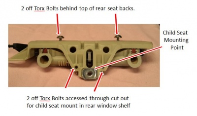
Manipulate the mechanism to expose the electrical connector and remove with long nose pliers. TIP: Be careful not to damage the connector as the plastic gets very brittle with age.
Manipulate the mechanism so that the white bellows can be removed.
Finally move the mechanism to the far left side of the car inside the access hole and withdraw the right side of the mechanism through the aperture first.
Often you will find that several plastic lugs holding the actuator together have broken and allowed the actuator to leak slightly as well as become dislodged.
3. Remove Rear Right Head-rest/Restraint Mechanism The Rear Right Head-rest/Restraint Mechanism is removed in a similar fashion to the left side. Use the steps for removing left head rest above.
Later note: TIP: It is not necessary to remove the C-Pillar Trim or even block the Rear Window Shelf up out of the way as per paragraphs 3a, 4 and 5 following. The two screws adjacent to the child seat restraint mounting point can be removed through the hole above the child seat mounting point.
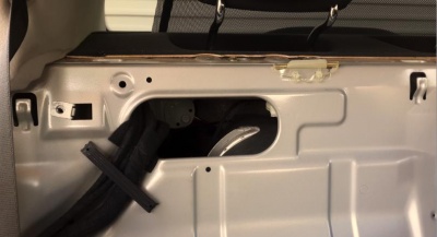
3a. If the tip in paragraph 12 doesn't work then use these steps. After removing the seats the Rear Right Head-rest/Restraint Mechanism is still not accessible until the rear window shelf is either removed or blocked up out of the way.
4. Remove the C-Pillar trim on both sides
5. Block the Rear Window Shelf up out of the way
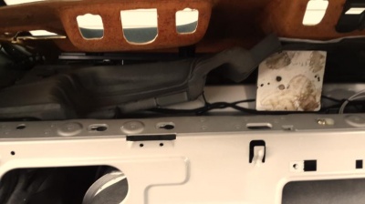
6. Remove Rear Right Head-rest/Restraint Mounting Screws Remove the two rear screws and loosen the two top screws which don’t need to be completely removed.

This is what it looked like after removal. The solenoid actuator had come detached completely.

This is what it should have looked like.

DIY Reinstall Mechanism - Rear Head-rest/Restraint
Reinstallation is just a matter of reversing the dismantling procedure. It is a good idea to use some dielectric grease (also used on spark plug wires) to lubricate the pneumatic lines before reconnecting them.
TIP: If you are remounting the new or repaired rear head-rest/restraint actuator (hockey puck) make sure that the slotted lever arm on the piston engages the pin on the head-rest mechanism.
DIY Repair Mechanism - Rear Head-rest/Restraint
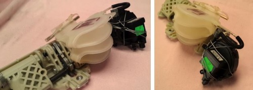
After removing and inspecting as above it is an easy matter to twitch some wire around the actuator to take the place of the broken lugs or to reinforce it so that it doesn’t come apart again. The remaining plastic lugs and the wire now take the strain of the piston when it is under pressure from the Pneumatic System Equipment (PSE) Pump when the head-rest/restraint is commanded to rise. Note this force is quite considerable.
Make really sure of an air tight seal by cleaning them with solvent and applying silicone to the base of the rubber cups before reassembling and then clamping the solenoid tightly together and leaving overnight for the silicone to completely set.
Head Rest/Restraint Button
Issues - Head Rest/Restraint Button
The buttons on the doors which control the Head Rest/Restraints are easily dislodged and lost. New or second hand buttons are not available and the whole EAS (Electrically Adjusted Seat) module is approximately $250. However it is an easy project to manufacture a new one.
DIY Repair/Replace/Manufacture - Head Rest/Restraint Button
Version 01 posted 2012-01-25 Post #5 at:
http://www.benzworld.org/forums/w220-s-class/1624796-seeking-rh-headrest-adjuster-button.html