MOST: Difference between revisions
m (→MOST ring open: link to COMAND-APS added) |
|||
| (12 intermediate revisions by 3 users not shown) | |||
| Line 1: | Line 1: | ||
== Digital MOST bus (Media Oriented System Transport) == | |||
MOST network with COMAND-APS was introduced starting from date 01/09/2003. Facelift vehicles from date 30/09/2002 to 01/09/2003 still had D2B, but widescreen COMAND. | |||
<!-- http://www.benzworld.org/forums/audio-telematics-forum/1696359-primer-audio-system-replacement-upgrade-enhancement.html --> | |||
<!-- GF82.00-P-0004AB MOST ring, function --> | |||
{| | |||
|[[File:W220_MOST_ring_components_USA.png]] | |||
| | |||
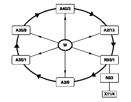
MOST ring components (shown for USA version): | |||
* w - Wake-up | |||
* A2/6 - [[MOST CD Changer|CD player with changer (in trunk)]] | |||
* A2/13 - [[MOST Sound Amplifier|Sound amplifier]] | |||
* A35/1 - Handsfree system control unit | |||
* A35/8 - E-call control unit | |||
* A40/3 - [[MOST COMAND-APS|COMAND operating, display and control unit]] | |||
* N93 - Central gateway control unit | |||
* N93/1 - [[MOST Audio Gateway|Audio gateway control unit]] | |||
* X11/4 - Data link connector | |||
|} | |||
[[File:MOST_optic_loop.jpg|300px]] | |||
The digital MOST bus is a data transfer system that utilizes the | |||
possibilities of optical information transfer. | |||
With this system, the data are transferred by light pulses. These | |||
are transmitted over a fiber optical cable to the components | |||
connected to the bus system (e.g. COMAND operating, display and | |||
control unit (A40/3), sound amplifier (A2/13)). | |||
Commands for the components, e.g. pressing "Play" button on | |||
COMAND operating, display and control unit (A40/3) for the CD | |||
player with changer (in trunk) (A2/6) have to be converted to light | |||
pulses (optical data) before being forwarded via the MOST. | |||
Light pulses are then converted back to electronic signals in the | |||
receiver components so that they can execute the commands. | |||
Because of its extremely high transfer rate the MOST ring source | |||
data and control data can be transmitted simultaneously. This | |||
reduces the quantity of wiring considerably. For this reason the | |||
connected components only require 2 lines for voltage supply, | |||
2 lines (input/output) for the fiber optical cable of the digital MOST | |||
bus and one line for the wake-up signal. | |||
Additionally, several audio frequency (AF) signals can be sent via | |||
the fiber optical cable, without compromising data content. | |||
Data transfer using a fiber optical cable has many advantages: | |||
* Extremely high data transmission rate | |||
* Prevents tapping and crosstalk | |||
* Data transmission is not sensitive to electromagnetic radiation | |||
* Short-circuit resistance | |||
* Potential-free connection of bus components | |||
* No oxidation | |||
* Low weight of fiber optical cable | |||
* Minimum diameter of wiring harness | |||
The MOST has an enclosed ring structure. The components are | |||
arranged in a ring line (series circuit). This arrangement is adapted | |||
according to the series. | |||
Data transfer ensues in one direction only, i.e. light pulses for the | |||
E-call control unit (A35/8) pass through all the components before | |||
it in the ring. | |||
Within the ring structure of the digital MOST bus the COMAND | |||
operating, display and control unit (A40/3) contains a primary | |||
function. This enables all other ring subscribers to be served. | |||
When the system is first put into operation, a system test is | |||
performed. In doing so the individual components and their | |||
sequence in the ring structure of the digital MOST bus are | |||
recorded by the audio gateway control unit (N93/1) and compared | |||
against the source and control data of the equipment-specific | |||
sequence of the data stored at the plant. | |||
With the assistance of STAR DIAGNOSIS the components in the | |||
audio gateway control unit (N93/1) can be re-coded (e.g. variant | |||
coding). | |||
The digital MOST Bus is rendered diagnosis capable via the audio | |||
gateway control unit (N93/1). | |||
== Data transfer in the MOST bus == | |||
<!-- GF82.00-P-2000AB Data transfer, function --> | |||
The audio gateway control unit (N93/1) makes it possible to | |||
provide all the data on the CAN interior compartment to each | |||
respective component. It acts as an interface (gateway). To this | |||
end signals arriving at the audio gateway control unit (N93/1) are | |||
converted such that they can be sent by the MOST to the CAN | |||
interior compartment and vice versa. It acts as the clock generator, | |||
with which data sections (data frames) are sent to the bus system. A | |||
data frame here consists of 2 subframes. | |||
The sequence of several data frames then contains the entire data | |||
required for operation of the components in the MOST ring. | |||
Light pulses are converted into electrical signals and back again by | |||
means of the optical transmitter and receiver diodes, which are | |||
integrated into every MOST component. | |||
The components can then receive or transmit the electrical signals. | |||
Source data (music and language) and control data (CD selection | |||
and muting during incoming telephone calls) are transmitted. | |||
The source data are sent synchronously, such as, for example on a | |||
music CD, as blocks in subframes. By contrast, the control data | |||
are transferred asynchronously. They are split up, distributed using | |||
several subframes and transmitted. | |||
The control data are provided with an address (Code), which | |||
indicates for which components the information is intended in the | |||
MOST ring. | |||
Data arriving at the components are combined to form individual | |||
data packages and can then be edited. A data frame can thus | |||
contain the most varied of information (source and control data of | |||
all the components in the MOST ring). | |||
The transmitting and receiving units are switched off when they are | |||
not required, in order to lower the quiescent current (sleep mode). | |||
They are switched off immediately after the operating unit is turned | |||
off or after the transmitter key is removed (A8/1). | |||
With a new optical information transmission start, the bus system | |||
can be activated with the help of the "ON" switch (ON/OFF) of the | |||
operating module or by turning the transmitter key (A8/1) to | |||
"terminal 15R ON", provided that the system was not shut off | |||
before the transmitter key (A8/1) was removed. This activation | |||
occurs by means of an electrical signal in the wake-up line, | |||
triggered by the audio gateway control unit (N93/1). | |||
If a telephone is integrated and the transmitter key inserted, a | |||
wake-up can also be triggered in the event of an incoming call. | |||
Irrespective of whether information is intended for a component at | |||
the start, the processed light pulse reenters the bus at full intensity. | |||
== Wake-up function == | |||
<!-- GF82.00-P-2001AB Wake-up, function --> | |||
=== Normal wake-up (all) === | |||
As the transmission and receiver diodes are automatically | |||
switched off when not required (sleep mode) at the start of new | |||
data transfer a command is required by the COMAND operating, | |||
display and control unit (A40/3) and/or a wake-up pulse which | |||
activates the system. This happens over a separate wake-up line. | |||
For this purpose the audio gateway control unit (N93/1) triggers a | |||
wake-up signal (electrical signal), which lowers the voltage in the | |||
wake-up line to a defined value. A chip in the components | |||
recognizes on account of the signal's duration that the signal in | |||
question is a wake-up signal, and the MOST ring is then activated. | |||
A wake-up can also be triggered by an incoming telephone call | |||
through the corresponding component during the run-out phase. | |||
===Diagnosis wake-up=== | |||
For diagnosis of the wake-up circuit in the components, the audio | |||
gateway control unit (N93/1) can be instructed by STAR | |||
DIAGNOSIS to trigger a wake-up diagnosis signal. | |||
This signal differentiates itself from the wake-up signal through its | |||
distinctly longer duration. The components for their part react with a | |||
signal to the wake-up line (message to the audio gateway control | |||
unit (N93/1)). | |||
With this the audio gateway control unit (N93/1) can then detect, | |||
which components have received the long wake-up pulse. The | |||
diagnosis wake-up signal can only be triggered if the optical ring | |||
cannot be activated due to a fault. If all components answer the | |||
audio gateway control unit (N93/1), the voltage supply is correct. | |||
== Fiber optic cable == | |||
<!-- GF82.00-P-4000-04AB Fiber optic cable, function --> | |||
The fiber optical cable is a transfer medium in which the signal is | |||
transmitted by means of modulated light. The basis material used | |||
for the fiber optical cable is plastic with a fiber diameter of approx. | |||
1 mm. A reflection layer in the core enables light signals to be | |||
transmitted between several control units. Each integrated control | |||
unit can transmit and receive signals and data. Located at the | |||
input and output of the fiber optical cable is an optoelectronic | |||
converter. The source device converts electrical signals into light | |||
signals and sends them via the fiber optical cable to the target | |||
device. Once at the target device they are converted back to | |||
electrical signals again. | |||
The light for the data transfer in the MOST has a wavelength of | |||
650 nm (unit: nanometer). By way of comparison: visible light lies | |||
in a range of blue with 400 nm to red with 800 nm. | |||
Optical attenuation of the light signal may occur in the fiber optical | |||
cable. The attenuation is dependent on: | |||
* the length of the line between the components | |||
* bending radius when routing (minimum bending radius 25 mm). | |||
* the condition of the insulation of the fiber optical cable (mechanical damage, pinching). | |||
* passive connectors (these are used when a component is removed from the MOST because it has failed). | |||
In order to assure the functional availability of the remaining components, | |||
the ring can be closed again with the passive | |||
connector. | |||
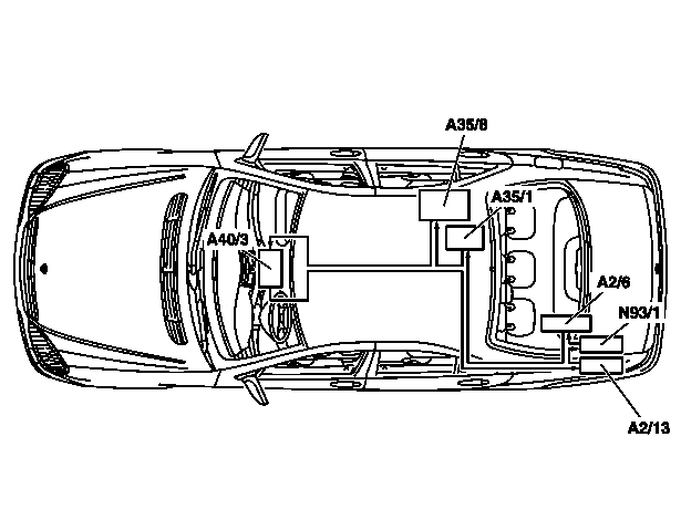
<!-- GF82.00-P-4000AB Fiber optical cable, location/task/function --> | |||
{| | |||
|[[File:W220_MOST_cable_location.png]] | |||
| | |||
Location (shown on model 220 USA version): | |||
* A2/6 - CD player with changer (in trunk) | |||
* A2/13 - Sound amplifier | |||
* A35/1 - Handsfree system control unit | |||
* A35/8 - E-call control unit | |||
* A40/3 - COMAND operating, display and control unit | |||
* N93/1 - Audio gateway control unit | |||
|} | |||
== Cables and connectors == | |||
'''Coupler or Splice Connector used for adding new MOST device''' | |||
[[File:MOST_optic_extension.jpg|300px|center]] | |||
'''Bypass terminator used for removing a MOST device''' | |||
[[File:MOST_optic_loop.jpg|300px|center]] | |||
'''Passive connector to extend MOST cable (A0005454484)''' | |||
[[File:MOST_optic_cable_extension.jpg|300px|center]] | |||
'''MOST connector dissected''' | |||
[[File:MOST_connector_dissected.jpg|300px|center]] | |||
'''MOST 2-pin plug (A0025459040)''' | |||
[[File:A0025459040_MOST_2-pin_plug.jpg|300px|center]] | |||
'''MOST housing for 2-pin plug (A0015452030)''' | |||
[[File:A0015452030.jpg|300px|center]] | |||
'''MOST and MQS 4-pin housing (A0005458430)''' | |||
[[File:A0005458430_MOST_and_MQS_4-pin_housing.jpg|300px|center]] | |||
'''MQS 4-pin plug (A0025458440)''' | |||
[[File:A0025458440_MQS_4-pin_plug.jpg|300px|center]] | |||
== MOST ring open == | |||
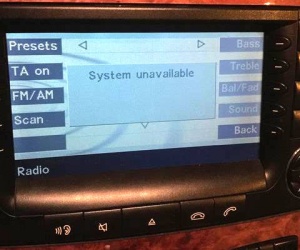
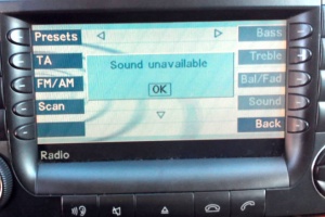
If MOST ring is open due to some failed MOST device or broken optical connection, the [[MOST COMAND-APS|COMAND-APS]] will show "System unavailable" and "sound unavailable" error messages after which the COMAND will shut down. | |||
[[File:W220_COMAND-APS_error_system_unavailable.jpg|300px]] | |||
[[File:W220_COMAND-APS_error_sound_unavailable.jpg|300px]] | |||
Latest revision as of 13:47, 26 August 2017
Digital MOST bus (Media Oriented System Transport)
MOST network with COMAND-APS was introduced starting from date 01/09/2003. Facelift vehicles from date 30/09/2002 to 01/09/2003 still had D2B, but widescreen COMAND.
|
MOST ring components (shown for USA version):
|
The digital MOST bus is a data transfer system that utilizes the
possibilities of optical information transfer.
With this system, the data are transferred by light pulses. These
are transmitted over a fiber optical cable to the components
connected to the bus system (e.g. COMAND operating, display and
control unit (A40/3), sound amplifier (A2/13)).
Commands for the components, e.g. pressing "Play" button on
COMAND operating, display and control unit (A40/3) for the CD
player with changer (in trunk) (A2/6) have to be converted to light
pulses (optical data) before being forwarded via the MOST.
Light pulses are then converted back to electronic signals in the receiver components so that they can execute the commands. Because of its extremely high transfer rate the MOST ring source data and control data can be transmitted simultaneously. This reduces the quantity of wiring considerably. For this reason the connected components only require 2 lines for voltage supply, 2 lines (input/output) for the fiber optical cable of the digital MOST bus and one line for the wake-up signal. Additionally, several audio frequency (AF) signals can be sent via the fiber optical cable, without compromising data content.
Data transfer using a fiber optical cable has many advantages:
- Extremely high data transmission rate
- Prevents tapping and crosstalk
- Data transmission is not sensitive to electromagnetic radiation
- Short-circuit resistance
- Potential-free connection of bus components
- No oxidation
- Low weight of fiber optical cable
- Minimum diameter of wiring harness
The MOST has an enclosed ring structure. The components are arranged in a ring line (series circuit). This arrangement is adapted according to the series. Data transfer ensues in one direction only, i.e. light pulses for the E-call control unit (A35/8) pass through all the components before it in the ring.
Within the ring structure of the digital MOST bus the COMAND operating, display and control unit (A40/3) contains a primary function. This enables all other ring subscribers to be served. When the system is first put into operation, a system test is performed. In doing so the individual components and their sequence in the ring structure of the digital MOST bus are recorded by the audio gateway control unit (N93/1) and compared against the source and control data of the equipment-specific sequence of the data stored at the plant. With the assistance of STAR DIAGNOSIS the components in the audio gateway control unit (N93/1) can be re-coded (e.g. variant coding). The digital MOST Bus is rendered diagnosis capable via the audio gateway control unit (N93/1).
Data transfer in the MOST bus
The audio gateway control unit (N93/1) makes it possible to provide all the data on the CAN interior compartment to each respective component. It acts as an interface (gateway). To this end signals arriving at the audio gateway control unit (N93/1) are converted such that they can be sent by the MOST to the CAN interior compartment and vice versa. It acts as the clock generator, with which data sections (data frames) are sent to the bus system. A data frame here consists of 2 subframes. The sequence of several data frames then contains the entire data required for operation of the components in the MOST ring.
Light pulses are converted into electrical signals and back again by means of the optical transmitter and receiver diodes, which are integrated into every MOST component. The components can then receive or transmit the electrical signals. Source data (music and language) and control data (CD selection and muting during incoming telephone calls) are transmitted. The source data are sent synchronously, such as, for example on a music CD, as blocks in subframes. By contrast, the control data are transferred asynchronously. They are split up, distributed using several subframes and transmitted.
The control data are provided with an address (Code), which indicates for which components the information is intended in the MOST ring. Data arriving at the components are combined to form individual data packages and can then be edited. A data frame can thus contain the most varied of information (source and control data of all the components in the MOST ring). The transmitting and receiving units are switched off when they are not required, in order to lower the quiescent current (sleep mode). They are switched off immediately after the operating unit is turned off or after the transmitter key is removed (A8/1).
With a new optical information transmission start, the bus system can be activated with the help of the "ON" switch (ON/OFF) of the operating module or by turning the transmitter key (A8/1) to "terminal 15R ON", provided that the system was not shut off before the transmitter key (A8/1) was removed. This activation occurs by means of an electrical signal in the wake-up line, triggered by the audio gateway control unit (N93/1).
If a telephone is integrated and the transmitter key inserted, a wake-up can also be triggered in the event of an incoming call.
Irrespective of whether information is intended for a component at the start, the processed light pulse reenters the bus at full intensity.
Wake-up function
Normal wake-up (all)
As the transmission and receiver diodes are automatically switched off when not required (sleep mode) at the start of new data transfer a command is required by the COMAND operating, display and control unit (A40/3) and/or a wake-up pulse which activates the system. This happens over a separate wake-up line. For this purpose the audio gateway control unit (N93/1) triggers a wake-up signal (electrical signal), which lowers the voltage in the wake-up line to a defined value. A chip in the components recognizes on account of the signal's duration that the signal in question is a wake-up signal, and the MOST ring is then activated. A wake-up can also be triggered by an incoming telephone call through the corresponding component during the run-out phase.
Diagnosis wake-up
For diagnosis of the wake-up circuit in the components, the audio gateway control unit (N93/1) can be instructed by STAR DIAGNOSIS to trigger a wake-up diagnosis signal. This signal differentiates itself from the wake-up signal through its distinctly longer duration. The components for their part react with a signal to the wake-up line (message to the audio gateway control unit (N93/1)). With this the audio gateway control unit (N93/1) can then detect, which components have received the long wake-up pulse. The diagnosis wake-up signal can only be triggered if the optical ring cannot be activated due to a fault. If all components answer the audio gateway control unit (N93/1), the voltage supply is correct.
Fiber optic cable
The fiber optical cable is a transfer medium in which the signal is transmitted by means of modulated light. The basis material used for the fiber optical cable is plastic with a fiber diameter of approx. 1 mm. A reflection layer in the core enables light signals to be transmitted between several control units. Each integrated control unit can transmit and receive signals and data. Located at the input and output of the fiber optical cable is an optoelectronic converter. The source device converts electrical signals into light signals and sends them via the fiber optical cable to the target device. Once at the target device they are converted back to electrical signals again.
The light for the data transfer in the MOST has a wavelength of 650 nm (unit: nanometer). By way of comparison: visible light lies in a range of blue with 400 nm to red with 800 nm.
Optical attenuation of the light signal may occur in the fiber optical cable. The attenuation is dependent on:
- the length of the line between the components
- bending radius when routing (minimum bending radius 25 mm).
- the condition of the insulation of the fiber optical cable (mechanical damage, pinching).
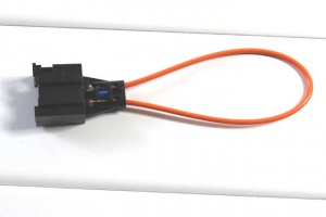
- passive connectors (these are used when a component is removed from the MOST because it has failed).
In order to assure the functional availability of the remaining components, the ring can be closed again with the passive connector.
Cables and connectors
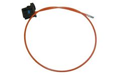
Coupler or Splice Connector used for adding new MOST device
Bypass terminator used for removing a MOST device
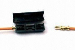
Passive connector to extend MOST cable (A0005454484)
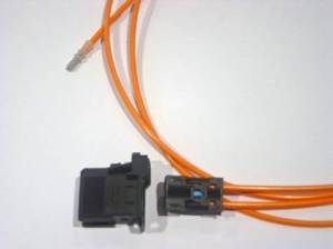
MOST connector dissected
MOST 2-pin plug (A0025459040)
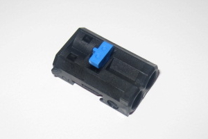
MOST housing for 2-pin plug (A0015452030)
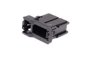
MOST and MQS 4-pin housing (A0005458430)
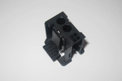
MQS 4-pin plug (A0025458440)
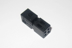
MOST ring open
If MOST ring is open due to some failed MOST device or broken optical connection, the COMAND-APS will show "System unavailable" and "sound unavailable" error messages after which the COMAND will shut down.
