Pneumatic System Equipment (PSE) Pump: Difference between revisions
Ricebubbles (talk | contribs) m (Removed link to WIS 80.20 Central Locking System, Interior Central Locking as it no longer works!!!!!) |
|||
| (4 intermediate revisions by 2 users not shown) | |||
| Line 1: | Line 1: | ||
==Description== | |||
The [[Pneumatic System Equipment (PSE)]] Pump does the closing of the doors and trunk with pressure. It either increases or decreases the pressure in the lines causing the movement of pistons in actuators, which in turn move levers in the various latches, which pull the doors or trunk closed. | |||
==Description | |||
The Pneumatic System Equipment (PSE) Pump does the closing of the doors and trunk with pressure. It either increases or decreases the pressure in the lines causing the movement of pistons in actuators, which in turn move levers in the various latches, which pull the doors or trunk closed. | |||
Notice that the PSE Pump is very clever, and can both blow (create +ve pressure) and suck (create -ve pressure or vacuum). | Notice that the PSE Pump is very clever, and can both blow (create +ve pressure) and suck (create -ve pressure or vacuum). | ||
| Line 12: | Line 10: | ||
[[File:Pneumatic System Equipment or PSE Pump in Boot or Trunk.JPG|600px|center]] | [[File:Pneumatic System Equipment or PSE Pump in Boot or Trunk.JPG|600px|center]] | ||
==Functions | ==Functions== | ||
On a M-B W220 2003 Update S500 LWB: | On a M-B W220 2003 Update S500 LWB: | ||
* Locking/Unlocking of Doors, | * Locking/Unlocking of Doors, | ||
| Line 22: | Line 20: | ||
* [[WIS 88.50 Trunk/Boot Lid|Operation of the Boot/Trunk Catch for auto opening]]. | * [[WIS 88.50 Trunk/Boot Lid|Operation of the Boot/Trunk Catch for auto opening]]. | ||
==Summary of Designations and Functions | ==Summary of Designations and Functions== | ||
The W220 S-Class Pneumatic System Equipment (PSE) Pump has each Port designated with Capital Letters: | The W220 S-Class Pneumatic System Equipment (PSE) Pump has each Port designated with Capital Letters: | ||
| Line 71: | Line 69: | ||
|Grey connector /yellow air line | |Grey connector /yellow air line | ||
|BFT | |BFT | ||
|Front | |Front Passenger's (left or right depends on LHD or RHD) Door Lock and Soft/Self Close | ||
|- | |- | ||
|Grey connector /yellow air line | |Grey connector /yellow air line | ||
|FT | |FT | ||
|Front | |Front Driver's (left or right depends on LHD or RHD) Door Lock and Soft/Self Close | ||
|- | |- | ||
|Grey connector /grey air line | |Grey connector /grey air line | ||
| Line 82: | Line 80: | ||
|} | |} | ||
==Location | ==Location== | ||
===PSE Pump=== | ===PSE Pump=== | ||
The Pneumatic System Equipment (PSE) Pump is located in the Boot/Trunk in a foam lined compartment in the left rear fender well, above the GPS Navigation Unit and is hidden from view by the Boot/Trunk Liner. | The Pneumatic System Equipment (PSE) Pump is located in the Boot/Trunk in a foam lined compartment in the left rear fender well, above the GPS Navigation Unit and is hidden from view by the Boot/Trunk Liner. | ||
| Line 93: | Line 91: | ||
[[File:W220 Filter on End of Pneumatic Line Attached to PSE Port SK.JPG|300px|center]] | [[File:W220 Filter on End of Pneumatic Line Attached to PSE Port SK.JPG|300px|center]] | ||
==Part Numbers | ==Part Numbers== | ||
2003 Update W220 S500 OEM PSE Part Number: | 2003 Update W220 S500 OEM PSE Part Number: | ||
: >PP-TS20< | : >PP-TS20< | ||
| Line 114: | Line 112: | ||
* Another post says, I checked the part numbers on the compatibility, and although 220 800 05 48 is an older version than 220 800 11 48, they are interchangeable. | * Another post says, I checked the part numbers on the compatibility, and although 220 800 05 48 is an older version than 220 800 11 48, they are interchangeable. | ||
==Specification Values (Obtained by Measurement) | ==Specification Values (Obtained by Measurement)== | ||
===Pressure Regulated Switch=== | ===Pressure Regulated Switch=== | ||
The PSE Pump has a Pressure Regulated Switch which is adjustable. It can be accessed once the pump is removed and dismantled. | The PSE Pump has a Pressure Regulated Switch which is adjustable. It can be accessed once the pump is removed and dismantled. | ||
| Line 136: | Line 134: | ||
[[File:W220 PSE Pump Coil Resistances.JPG|400px|center]] | [[File:W220 PSE Pump Coil Resistances.JPG|400px|center]] | ||
==Baseline Pressure Tests | ==Baseline Pressure Tests== | ||
In order to establish a base line performance the following pressure tests were conducted and the results recorded as each feature was run through it’s full range of operation. | In order to establish a base line performance the following pressure tests were conducted and the results recorded as each feature was run through it’s full range of operation. | ||
| Line 144: | Line 142: | ||
{| class="wikitable" style="margin: auto;" | {| class="wikitable" style="margin: auto;" | ||
|+Baseline Pressure Tests | |+Baseline Pressure Tests | ||
|- | |- | ||
!style="text-align:center;"|PSE Pump Port Designation | !style="text-align:center;"|PSE Pump Port Designation | ||
| Line 186: | Line 184: | ||
|- | |- | ||
|BFT | |BFT | ||
|Front | |Front Passenger's Door (left or right depends on LHD or RHD) | ||
|Lock car using Remote Key, get +ve pressure (24Kpa or 3.5psi), which pulls Front Left Door Lock Button down, then returns to atmospheric pressure. | |Lock car using Remote Key, get +ve pressure (24Kpa or 3.5psi), which pulls Front Left Door Lock Button down, then returns to atmospheric pressure. | ||
Unlock car using Remote Key, get -ve pressure (9”Hg vacuum), which moves Front Left Door Lock Button up, then returns to atmospheric pressure. | Unlock car using Remote Key, get -ve pressure (9”Hg vacuum), which moves Front Left Door Lock Button up, then returns to atmospheric pressure. | ||
| Line 192: | Line 190: | ||
|- | |- | ||
|FT | |FT | ||
|Front | |Front Driver's Door ((left or right depends on LHD or RHD)) | ||
|Lock car using Remote Key, get +ve pressure (21Kpa or 3psi), which pulls Front Right Door Lock Button down, then returns to atmospheric pressure. | |Lock car using Remote Key, get +ve pressure (21Kpa or 3psi), which pulls Front Right Door Lock Button down, then returns to atmospheric pressure. | ||
Unlock car using Remote Key, get -ve pressure (9”Hg vacuum), which moves Front Right Door Lock Button up, then returns to atmospheric pressure. | Unlock car using Remote Key, get -ve pressure (9”Hg vacuum), which moves Front Right Door Lock Button up, then returns to atmospheric pressure. | ||
| Line 202: | Line 200: | ||
|} | |} | ||
==Issues | ==Issues== | ||
===Pump Fails to Work Due to Pneumatic Leaks=== | ===Pump Fails to Work Due to Pneumatic Leaks=== | ||
* The PSE pump contains electronics which has memory and will disable some functions if they do not work properly for whatever reason. For example a leak in a line or actuator may cause the pump to run for too long. The electronics may disable the pump in this situation. | * The PSE pump contains electronics which has memory and will disable some functions if they do not work properly for whatever reason. For example a leak in a line or actuator may cause the pump to run for too long. The electronics may disable the pump in this situation. | ||
| Line 238: | Line 236: | ||
|} | |} | ||
==Resetting | ==Resetting== | ||
Resetting of the PSE pump is accomplished by either pulling the 20 amp [[WIS 54.15 Fuse and Relay Box|fuse]] under the Rear Right Seat or disconnecting the main connector to the PSE pump for thirty seconds. | Resetting of the PSE pump is accomplished by either pulling the 20 amp [[WIS 54.15 Fuse and Relay Box|fuse]] under the Rear Right Seat or disconnecting the main connector to the PSE pump for thirty seconds. | ||
==Accessing | ==Accessing== | ||
'''Warning: DO NOT remove any of the Air Lines before ANNOTATING them. The PSE Pump Ports are marked but the Air Lines are not.''' | '''Warning: DO NOT remove any of the Air Lines before ANNOTATING them. The PSE Pump Ports are marked but the Air Lines are not.''' | ||
* Remove battery earth connection. | * Remove battery earth connection. | ||
| Line 256: | Line 254: | ||
To inspect the internals see section "Dismantling - PSE Pump" below. | To inspect the internals see section "Dismantling - PSE Pump" below. | ||
==Fault Codes | ==Fault Codes== | ||
{| class="wikitable" style="margin: auto;" | {| class="wikitable" style="margin: auto;" | ||
|+Fault Codes - Pneumatic System Equipment (PSE) Pump | |+Fault Codes - Pneumatic System Equipment (PSE) Pump | ||
| Line 307: | Line 305: | ||
|} | |} | ||
==Testing and DIY Repairs | ==Testing and DIY Repairs== | ||
===Test Pneumatic System by Observation=== | ===Test Pneumatic System by Observation=== | ||
| Line 344: | Line 342: | ||
|} | |} | ||
===Pressure Test Results | ===Pressure Test Results=== | ||
A vacuum gauge and a pressure gauge were teed together to make a +ve and -ve pressure tester which was then teed into each PSE Pump output port to measure the resulting operational pressures. | A vacuum gauge and a pressure gauge were teed together to make a +ve and -ve pressure tester which was then teed into each PSE Pump output port to measure the resulting operational pressures. | ||
[[File:Vacuum and Pressure Gauges Teed Together.JPG|400px|center]] | [[File:Vacuum and Pressure Gauges Teed Together.JPG|400px|center]] | ||
| Line 358: | Line 356: | ||
http://www.benzworld.org/forums/w220-s-class/1571979-pse-pump-air-lines.html | http://www.benzworld.org/forums/w220-s-class/1571979-pse-pump-air-lines.html | ||
===Internal Pneumatic Schematic | ===Internal Pneumatic Schematic=== | ||
A failed PSE Pump was sectioned through the base plate. This allowed the following: | A failed PSE Pump was sectioned through the base plate. This allowed the following: | ||
* investigation of the internal leakage paths, | * investigation of the internal leakage paths, | ||
| Line 392: | Line 390: | ||
https://web.archive.org/web/20120418063628/http://v12uberalles.com/Closing_Assist_Pump.htm | https://web.archive.org/web/20120418063628/http://v12uberalles.com/Closing_Assist_Pump.htm | ||
===Test Internal Pneumatic Pathways for Leakage | ===Test Internal Pneumatic Pathways for Leakage=== | ||
A PSE Pump that has overheated may have developed an internal leakage path between the electrical pump pressure port and the main manifold. The usual symptoms are that the pump fails to generate either or both positive pressure and vacuum. A typical failure pathway can be seen in this schematic. | A PSE Pump that has overheated may have developed an internal leakage path between the electrical pump pressure port and the main manifold. The usual symptoms are that the pump fails to generate either or both positive pressure and vacuum. A typical failure pathway can be seen in this schematic. | ||
[[File:W220 PSE Pump Internal Pneumatic Schematic in Internal Leak Testing Mode.JPG|500px|center]] | [[File:W220 PSE Pump Internal Pneumatic Schematic in Internal Leak Testing Mode.JPG|500px|center]] | ||
| Line 399: | Line 397: | ||
[[File:Internal Leak Testing Heat Damaged PSE Pump.JPG|500px|center]] | [[File:Internal Leak Testing Heat Damaged PSE Pump.JPG|500px|center]] | ||
===DIY Repair | ===DIY Repair=== | ||
====Dismantling | ====Dismantling==== | ||
Once the PSE pump is on the bench it can be dismantled: | Once the PSE pump is on the bench it can be dismantled: | ||
* Remove the three Torx screws on the top case. | * Remove the three Torx screws on the top case. | ||
| Line 427: | Line 425: | ||
[[File:W220 PSE Pump Internal Assembly.JPG|500px|center]] | [[File:W220 PSE Pump Internal Assembly.JPG|500px|center]] | ||
====DIY Output Port Leak Repair | ====DIY Output Port Leak Repair==== | ||
If the PSE Pump Output Port has not melted completely and you see small bubbles appearing in the base plate, then it may be possible to prevent it getting any worse. The small pinhole leak shown in the next photo was caused by a burst bubble in the softened plastic base. The position of the leak can be identified by the triangular pattern of dust. This pump was beyond repair as it also had severe internal leakage. | If the PSE Pump Output Port has not melted completely and you see small bubbles appearing in the base plate, then it may be possible to prevent it getting any worse. The small pinhole leak shown in the next photo was caused by a burst bubble in the softened plastic base. The position of the leak can be identified by the triangular pattern of dust. This pump was beyond repair as it also had severe internal leakage. | ||
[[File:PSE Closeup of Partially Melted Pump Output Port with Annotation.JPG|400px|center]] | [[File:PSE Closeup of Partially Melted Pump Output Port with Annotation.JPG|400px|center]] | ||
| Line 458: | Line 456: | ||
If you are lucky this should prevent any further blowouts in the plastic due to excess pump heat. To really be sure and to make the design better than the OEM design, add a heat radiator in the Output Port Pneumatic Line. (See below.) | If you are lucky this should prevent any further blowouts in the plastic due to excess pump heat. To really be sure and to make the design better than the OEM design, add a heat radiator in the Output Port Pneumatic Line. (See below.) | ||
====DIY Add a Heat Radiator in Output Port Line | ====DIY Add a Heat Radiator in Output Port Line==== | ||
If you want to avoid your pump from damaging the area around the output port due to heat (as shown above), then the addition of a heat transfer radiator in the output pressure pneumatic line will remove some of the excess heat and should avoid any resulting softening, bubbling and subsequent damage to the plastic base plate. | If you want to avoid your pump from damaging the area around the output port due to heat (as shown above), then the addition of a heat transfer radiator in the output pressure pneumatic line will remove some of the excess heat and should avoid any resulting softening, bubbling and subsequent damage to the plastic base plate. | ||
| Line 484: | Line 482: | ||
When tested after the pump was made to run by opening and closing the trunk several times, it was found that only one coil of the heat radiator got hot. | When tested after the pump was made to run by opening and closing the trunk several times, it was found that only one coil of the heat radiator got hot. | ||
====DIY Overhaul | ====DIY Overhaul==== | ||
A thorough description of a PSE Pump Overhaul by BenzWorld Member evolotion is at; | A thorough description of a PSE Pump Overhaul by BenzWorld Member evolotion is at; | ||
http://www.benzworld.org/forums/w220-s-class/1563160-pse-central-locking-pump-overhall.html | http://www.benzworld.org/forums/w220-s-class/1563160-pse-central-locking-pump-overhall.html | ||
==Lessons Learned | ==Lessons Learned== | ||
===Need to Annotate the Pneumatic Lines=== | ===Need to Annotate the Pneumatic Lines=== | ||
* DO NOT remove any of the Air Lines before ANNOTATING them. The PSE Pump Ports are marked but the Air Lines are not. | * DO NOT remove any of the Air Lines before ANNOTATING them. The PSE Pump Ports are marked but the Air Lines are not. | ||
| Line 499: | Line 497: | ||
====TIP to Avoid Reprogramming Replacement Pump==== | ====TIP to Avoid Reprogramming Replacement Pump==== | ||
You can avoid reprogramming a replacement pump if you swap over the original printed circuit board to the replacement pump. It does require some basic soldering skill. Be careful that you don't splatter solder all over the place and make sure you touch an earthed point before touching any electronic parts to avoid damage due to electrostatic discharge. | You can avoid reprogramming a replacement pump if you swap over the original printed circuit board to the replacement pump. It does require some basic soldering skill. Be careful that you don't splatter solder all over the place and make sure you touch an earthed point before touching any electronic parts to avoid damage due to electrostatic discharge. | ||
====Arduino Controlled PSE Pump==== | |||
If the original printed circuit board is faulty and you have no means to reprogram a replacement, an alternate solution is to create a [[Arduino Controlled PSE Pump|custom electronic controller using an Arduino]]. | |||
===Do Not Add Additional Lubrication=== | ===Do Not Add Additional Lubrication=== | ||
Latest revision as of 03:31, 24 July 2021
Description
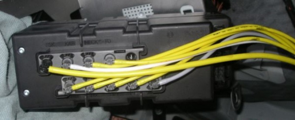
The Pneumatic System Equipment (PSE) Pump does the closing of the doors and trunk with pressure. It either increases or decreases the pressure in the lines causing the movement of pistons in actuators, which in turn move levers in the various latches, which pull the doors or trunk closed.
Notice that the PSE Pump is very clever, and can both blow (create +ve pressure) and suck (create -ve pressure or vacuum).
The negative pressure (vacuum) pulled by the PSE Pump may ensure retraction of various actuators but it also performs function in it’s own right, such as retracting the Boot/Trunk Handle.
Pneumatic System Equipment or PSE Pump in Boot or Trunk
Functions
On a M-B W220 2003 Update S500 LWB:
- Locking/Unlocking of Doors,
- Soft/Self Close Function for Trunk,
- Inflation of Lumbar Support Bladders,
- Operation of Fuel Filler Flap Lock, (For manual release see WIS 47.00 Fuel Filler Cover
- Extension and retraction of the Boot/Trunk Handle,
- Releases the Child Safety Lock on Rear Doors in an emergency, and
- Operation of the Boot/Trunk Catch for auto opening.
Summary of Designations and Functions
The W220 S-Class Pneumatic System Equipment (PSE) Pump has each Port designated with Capital Letters:
SK, KAF, HECK, TD, Blank
......FoR, FoL, BFT, FT and MKL.
See next Figure for PSE Pump Air Line Port Designations.
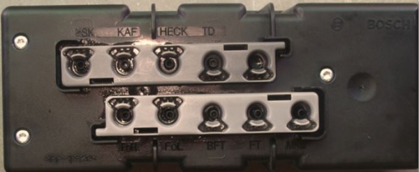
| Pneumatic System Equipment (PSE) Pump Port Connector and Air Line Colour | Designation | Function in W220 2003 Update S500L |
|---|---|---|
| Black connector/large yellow air line | SK | Main Inlet Line with Air Filter behind the Rear Left Seat Back |
| Grey connector /white air line | KAF | Rear Seat Head Restraints |
| Grey connector /yellow air line | HECK | Retractable Trunk Grip (RTG), Boot/Trunk Catch Actuator and Trunk Soft Close Mechanism |
| Grey connector /yellow air line | TD | Fuel Filler Flap Lock |
| Not Used | ||
| Grey connector /yellow air line | FoR | Rear Right Door Lock, Child Safety Door Lock Release and Soft/Self Close |
| Grey connector /yellow air line | FoL | Rear Left Door Lock , Child Safety Door Lock Release and Soft/Self Close |
| Grey connector /yellow air line | BFT | Front Passenger's (left or right depends on LHD or RHD) Door Lock and Soft/Self Close |
| Grey connector /yellow air line | FT | Front Driver's (left or right depends on LHD or RHD) Door Lock and Soft/Self Close |
| Grey connector /grey air line | MKL | Multi Contour Backrest (Lumbar Support Bladder all four seats) |
Location
PSE Pump
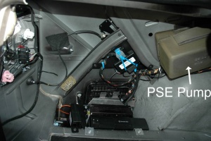
The Pneumatic System Equipment (PSE) Pump is located in the Boot/Trunk in a foam lined compartment in the left rear fender well, above the GPS Navigation Unit and is hidden from view by the Boot/Trunk Liner.
Inlet Air Filter
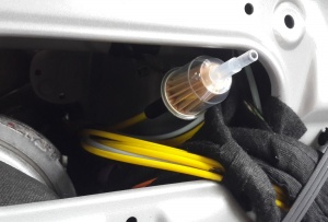
The PSE Pump SK port is attached via a large diameter yellow pneumatic line to the Inlet Air Filter which is located behind the rear left seat back.
Part Numbers
2003 Update W220 S500 OEM PSE Part Number:
- >PP-TS20<
- MB 220 800 10 48 [08]
- BOSCH 0 132 006 381
- (944)
- 0022 03190 10 0315 1 001 Made in France
As usual confusion reigns regarding part numbers.
- One BenzWorld Member called his dealer to verify the part number and apparently all the PSE vacuum pumps are the exact same pump, M-B just kept changing the part number every year,
- 220 800 02 48 is the oldest part number, then keeps going up to
- 220 800 03 48,
- 220 800 05 48,
- 220 800 10 48 etc.
But it’s all the same pump so they will all work.
- Another BenzWorld member says only the newest pump will work for sure. The difference is in the electronics basically. Older pumps for example do not support the remote trunk closure option.
- Another post says, I checked the part numbers on the compatibility, and although 220 800 05 48 is an older version than 220 800 11 48, they are interchangeable.
Specification Values (Obtained by Measurement)
Pressure Regulated Switch
The PSE Pump has a Pressure Regulated Switch which is adjustable. It can be accessed once the pump is removed and dismantled.
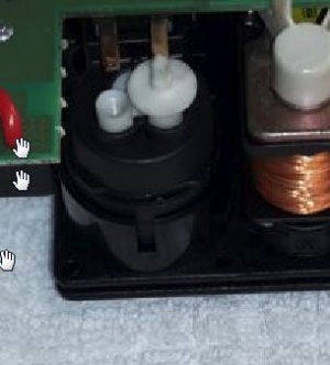
The Pressure Regulated Switch changes from a closed position to an open position at 27.6KPa (4psi).
Pressure at MKL Port
Contrary to the result obtained at the Pressure Switch the pressure measured at the MKL (Multicontour backrest) port was 82.7KPa (12psi). The WIS specification states "A pressure of approx. (700...950) mbar is produced at the pump outlet 'MKL'." and "If the pressure has dropped to (500...650) mbar, the control module operates and produces pressure".
Thus the PSE Pump (A37) should;
- switch off at 700 to 950 mbar or 70 to 95 KPa or 10.1 to 13.8 psi.
- switch on at 500 to 650 mbar or 50 to 65 KPa or 7.3 to 9.4 psi.
Solenoid Coil Resistance
The PSE Pump has ten solenoid valves. The coils have a resistance of 34.0 Ohms +/-0.1.
Note the resistance may be measured in situ, ie without unsoldering and removing the printed circuit board.
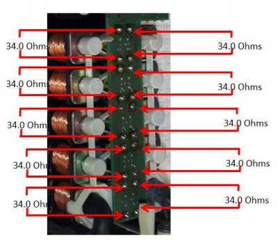
Baseline Pressure Tests
In order to establish a base line performance the following pressure tests were conducted and the results recorded as each feature was run through it’s full range of operation.
The pressure readings were obtained with a home made dual gauge set, comprising a Vacuum Gauge and a Pressure Gauge teed together, and then this dual gauge teed into each air line in turn.
The appropriate function was then operated as per normal whilst observing the dual gauges. By necessity each air line had to be disconnected and then reconnected with the tee piece in line for each test. This may have some impact on the results as the Pump is very aware that the line has been disconnected. According to Brett Allison in the reference, the W140 Close Assist Pump will cease to control a particular air line if it detects a fault several times in a row. This condition is corrected by unplugging the large connector on the PSE Pump, waiting a minute or so and reconnecting, which apparently resets the electronics.
| PSE Pump Port Designation | Function in W220 2003 Update S500 LWB | Pressure Tests (Note Non-Existent Soft Close Function on All Doors) |
|---|---|---|
| SK | Main Inlet Line with Filter | Main Inlet Line with Filter behind the Rear Left Seat Back |
| KAF | Rear Seat Head Restraints | Switch Head Restraints up, get +ve pressure (27KPa, 4psi), the head restraints go up, then returns to atmospheric pressure.
Switch Head Restraints down, no change in pressure (atmospheric), Head Restraints go down. |
| HECK | Retractable Trunk Grip (RTG) Boot/Trunk Catch Actuator and Trunk Soft Close Mechanism | Manually close Boot/Trunk by pulling down on RTG Handle until latch goes click, get +ve pressure (27KPa, 4psi), Boot/Trunk Catch Actuator pulls boot closed, then –ve pressure (19”Hg vacuum), which retracts RTG Handle, then returns to atmospheric pressure.
Open Boot/Trunk with either remote control on key fob, driver’s door trunk release switch or switch on trunk lid, get +ve pressure (27KPa, 4psi), which extends RTG Handle, and unlocks Boot/Trunk latch, releasing lid which fully opens, then returns to atmospheric pressure. |
| TD | Fuel Filler Flap Lock | Lock car using Remote Key, get +ve pressure (28Kpa or 4psi), which moves pin out to lock Fuel Filler Flap, then returns to atmospheric pressure.
Unlock car using Remote Key, get -ve pressure (8”Hg vacuum), which retracts pin to unlock Fuel Filler Flap, then returns to atmospheric pressure. |
| Not Used | ||
| FoR | Rear Right Door | Lock car using Remote Key, get +ve pressure (14Kpa or 2psi), which pulls Rear Right Door Lock Button down, then returns to atmospheric pressure.
Unlock car using Remote Key, get -ve pressure (9”Hg vacuum), which moves Rear Right Door Lock Button up, then returns to atmospheric pressure. Soft Close Feature (Where Fitted TBD) |
| FoL | Rear Left Door | Lock car using Remote Key, get +ve pressure (24Kpa or 3.5psi), which pulls Rear Left Door Lock Button down, then returns to atmospheric pressure.
Unlock car using Remote Key, get -ve pressure (9”Hg vacuum) which moves Rear Left Door Lock Button up, then returns to atmospheric pressure. Soft Close Feature (Where Fitted TBD) |
| BFT | Front Passenger's Door (left or right depends on LHD or RHD) | Lock car using Remote Key, get +ve pressure (24Kpa or 3.5psi), which pulls Front Left Door Lock Button down, then returns to atmospheric pressure.
Unlock car using Remote Key, get -ve pressure (9”Hg vacuum), which moves Front Left Door Lock Button up, then returns to atmospheric pressure. Soft Close Feature (Where Fitted TBD) |
| FT | Front Driver's Door ((left or right depends on LHD or RHD)) | Lock car using Remote Key, get +ve pressure (21Kpa or 3psi), which pulls Front Right Door Lock Button down, then returns to atmospheric pressure.
Unlock car using Remote Key, get -ve pressure (9”Hg vacuum), which moves Front Right Door Lock Button up, then returns to atmospheric pressure. Soft Close Feature (Where Fitted TBD) |
| MKL | Multi Contour Backrest (Lumbar Support Bladder all seats) | When the MKL Air Line is connected it always has +ve pressure (55Kpa or 8psi). If the MKL Air Line is disconnected each Lumbar Support Bladder remains inflated until it’s Adjustment Control on the edge of the seat is returned to ‘0’. You can hear the air escaping from the Adjustment Control. |
Issues
Pump Fails to Work Due to Pneumatic Leaks
- The PSE pump contains electronics which has memory and will disable some functions if they do not work properly for whatever reason. For example a leak in a line or actuator may cause the pump to run for too long. The electronics may disable the pump in this situation.
- The solution is to reset the pump which should restore functionality, even if temporarily. If the fault persists the pump will most likely be disabled again.
Pump Fails to Work Due to Blocked Pump Ports
- Some functions may not work due to a build up of a fine black powder inside the PSE pump which blocks the relevant port.
- The solution is to dismantle the pump and clean any contamination from the pump head or internal lines. The following contaminated area was provided by BenzWorld poster, GotBenz.
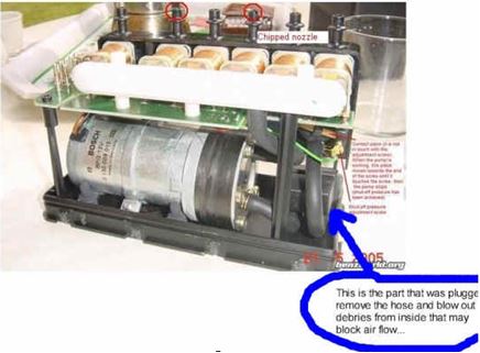
Pump Fails to Work Due to Over Heating
- The Retractable Trunk Grip (RTG) ie the pneumatically controlled hidden chrome handle failed when the car was locked and left parked. Next morning the car wouldn’t unlock because the battery voltage had drained to 6.4V. The PSE pump had been running all night and melted the discharge plastic port on the pump.
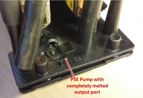
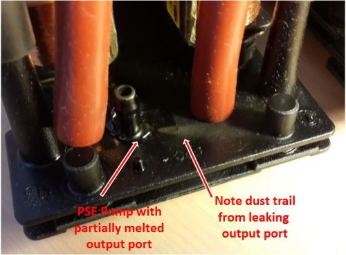
- In this example the PSE pump output port is still intact but is leaking through a small hole which was created when the heat from the pump softened the plastic. After doing the Internal Leak Testing described below it the pump was found to have a severe internal leak due to heat damage and was unusable.
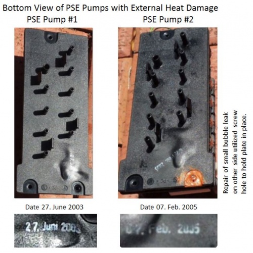
- The next photo shows two W220 PSE Pumps with severe external heat damaged base plates. Both pumps were unusable.
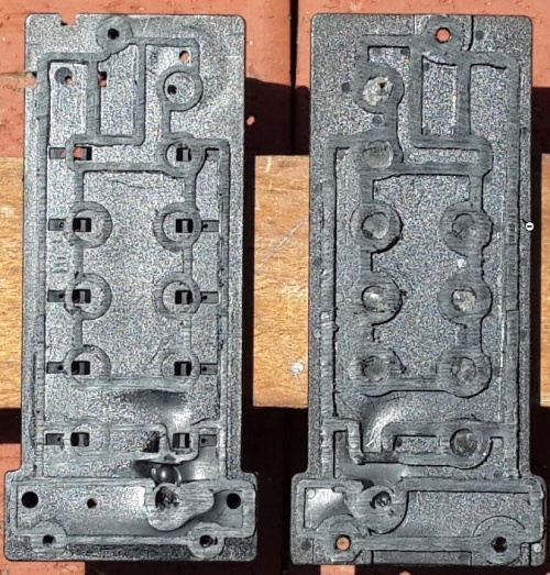
- The next photo shows a heat damaged PSE pump which has been cut open to reveal the internal leak.
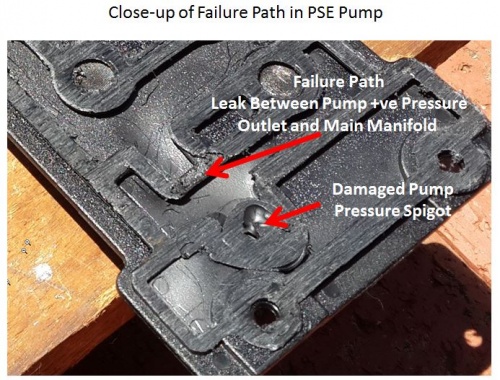
And a close-up of the leakage path.
- The easy solution is to buy a new or second hand pump and after fitting reprogram the pump to the car using STAR.
- If the PSE Pump Output Port is still intact and the pump doesn't show any of the signs of bubbling due to heat, a pressure tensioner can be added for extra strength. See below for DIY Repair.
- Even if the pump is in good condition and doesn't show any signs of damage due to heat it is a good idea to add a heat radiator to remove some of the Output Port heat generated by the pump. See below for DIY Solution.
Resetting
Resetting of the PSE pump is accomplished by either pulling the 20 amp fuse under the Rear Right Seat or disconnecting the main connector to the PSE pump for thirty seconds.
Accessing
Warning: DO NOT remove any of the Air Lines before ANNOTATING them. The PSE Pump Ports are marked but the Air Lines are not.
- Remove battery earth connection.
- Remove the plastic panel at the rear most edge of the Boot/Trunk opening.
- Remove Trunk/boot left side lining. See WIS 88.50 Trunk/Boot Lid.
- It helps to remove the Boot/Trunk Lining under the back window after also removing the Battery Cover and the right Boot/Trunk liner but it is not absolutely necessary.
- It is not necessary to touch either the GPS Navigation or the CD Player.
- Remove TV Tuner if fitted.
- Remove insulating cover from PSE Pump.
- Withdraw PSE Pump from its insulated box.
- Annotate each line with the designation matching that found on the PSE Pump.
- Note the Air Lines are connected to the pump by snap-on connectors.
To inspect the internals see section "Dismantling - PSE Pump" below.
Fault Codes
| Code | Fault |
|---|---|
| B1436-012 | The safety time of the central locking has been exceeded for the following pneumatic branch: Driver's door. |
| B1436-014 | The safety time of the central locking has been exceeded for the following pneumatic branch: Front passenger door or rear doors |
| B1436-015 | The safety time of the central locking has been exceeded for the following pneumatic branch: Passenger door. |
| B1436-016 | The safety time of the central locking has been exceeded for the following pneumatic branch: Left rear door. |
| B1436-017 | The safety time of the central locking has been exceeded for the following pneumatic branch: Right rear door. |
| B1437 | The safety time has been exceeded for the following pneumatic branch: Lower or raise rear head restraints. |
| B1438-011 | The air demand of the multicontour backrest is too high. |
| B1438-012 | The safety time has been exceeded for the following pneumatic branch: Multicontour backrest. |
| B1440 | The safety time has been exceeded for the following pneumatic branch: Trunk lid
remote release. |
| B1442-012 | The safety time of the power closing has been exceeded for the following pneumatic branch: Driver's door. |
| B1442-015 | The safety time of the power closing has been exceeded for the following pneumatic branch: Passenger door. |
| B1442-016 | The safety time of the power closing has been exceeded for the following pneumatic branch: Left rear door. |
| B1442-017 | The safety time of the power closing has been exceeded for the following pneumatic branch: Right rear door. |
| B1442-018 | The safety time of the power closing has been exceeded for the following pneumatic branch: Trunk lid. |
Testing and DIY Repairs
Test Pneumatic System by Observation
There is an easy test to see if it's all working properly. With the boot open and the pump visible, use a screwdriver to carefully trip the catch in the boot lid, basically tricking it into thinking it's time to close. The catch shuts and you can clearly hear the how long the pump is on for. It should stop after no more than 5 seconds. If it runs on to 12-16 seconds, it's logging an error and the close assist system will stop working after five or six operations.
After rebuild it should take only 3 seconds to close, before it was taking 16 seconds.
Test Pneumatic Lines for Leakage
The best method for determining which lines are leaking is to perform leakage tests on each pneumatic line when disconnected from the PSE Pump. Firstly remove the PSE Pump.
Remove PSE Pump
To access and remove the PSE Pump refer to section "Accessing - Pneumatic System Equipment (PSE) Pump" above.
Leakage Testing Pneumatic Lines
- Carefully prise one pneumatic line from the PSE port.
- Connect a MityVac hand operated vacuum pump to the open pneumatic line.
- Apply negative vacuum. (Note some long lines with large actuators will require considerable pumping.
- Observe the result on the MityVac gauge. It should hold a steady vacuum if there are no leaks.
- If leaks are observed you will need to work your way towards the relevant actuator and repeat wherever it is convenient.
- Replace the pneumatic line.
- Repeat the vacuum test on the next pneumatic line.
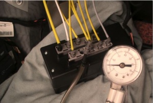
Leakage Testing Pneumatic Lines Using Smoke Machine
Pressure Test Results
A vacuum gauge and a pressure gauge were teed together to make a +ve and -ve pressure tester which was then teed into each PSE Pump output port to measure the resulting operational pressures.
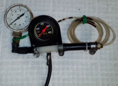
See Section above [1]
A thorough description and results of pressure tests can be found at BenzWorld Post #15:
http://www.benzworld.org/forums/w220-s-class/1631298-does-my-s500-have-soft-self-2.html
and 2002 S430 Pneumatic System Equipment (PSE) Pump at:
http://www.benzworld.org/forums/w220-s-class/1571979-pse-pump-air-lines.html
Internal Pneumatic Schematic
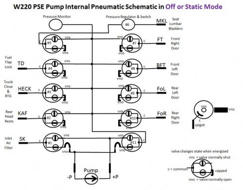
A failed PSE Pump was sectioned through the base plate. This allowed the following:
- investigation of the internal leakage paths,
- determination of the pneumatic schematic and
- development of a leakage test method.
Schematic of Internal Pneumatic Pathways and Solenoid Valves in Static (Off) Mode
Note orientation of diagrams is as viewed from the bottom or port side of the PSE pump.
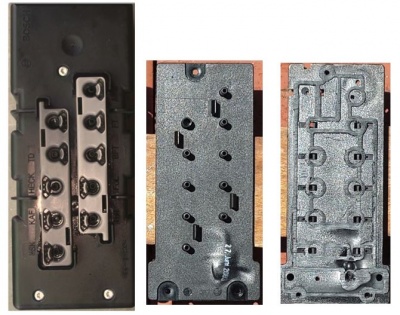
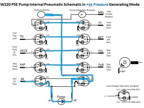
Schematic of Internal Pneumatic Pathways and Solenoid Valves in +ve Pressure Generating Mode
The blue highlight shows the air pathway when the PSE Pump is generating positive pressure. Solenoid valve #11 is energised for positive pressure mode. There may be other valves energised as well depending on the demand.
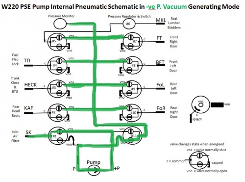
Schematic of Internal Pneumatic Pathways and Solenoid Valves in Suction, -ve Pressure or Vacuum Generating Mode
The green highlight shows the air pathway when the PSE Pump is generating vacuum. Solenoid valve #1 is energised for vacuum mode. There may be other valves energised as well depending on the demand.
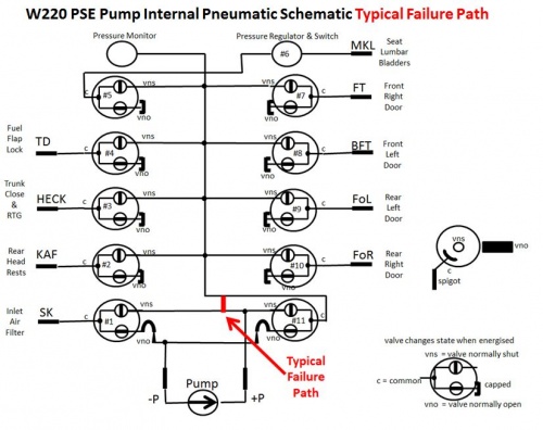
Schematic of a Typical Internal Pneumatic Pathway Failure
As shown in several examples above, excessive heat generated by prolonged operation of the electrical pump will cause softening and subsequent ballooning of the base plate, external damage and eventually internal failure of the pneumatic pathways leading to severe leakage between the pressure port and the main manifold as shown in red in the next image.
Understanding a PSE Pump
An excellent article by Brett Allison titled "Getting to know your Closing Assist Pump: Function, Tips, and Fixes" is at:
https://web.archive.org/web/20120418063628/http://v12uberalles.com/Closing_Assist_Pump.htm
Test Internal Pneumatic Pathways for Leakage
A PSE Pump that has overheated may have developed an internal leakage path between the electrical pump pressure port and the main manifold. The usual symptoms are that the pump fails to generate either or both positive pressure and vacuum. A typical failure pathway can be seen in this schematic.
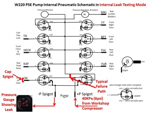
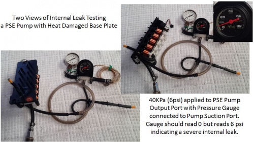
For this test the SK (Inlet Air Filter) port must be capped or plugged. An air compressor, which has been set to supply a maximum of 40KPa (6psi), is attached to the base plate pump pressure port. A pressure gauge is attached to the base plate pump suction port. There should be no pressure showing on the gauge. In this example the faulty PSE base plate has a severe internal leakage and the test gauge is showing a full 6psi reading. This pump is only good for the bin.
DIY Repair
Dismantling
Once the PSE pump is on the bench it can be dismantled:
- Remove the three Torx screws on the top case.
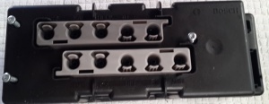
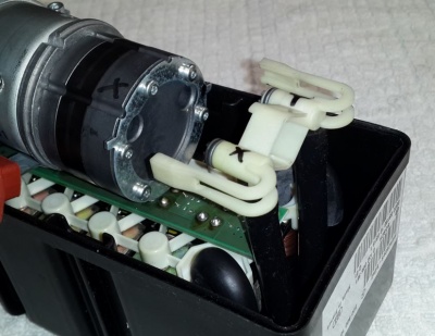
- Release the tabs (2 each) on the two grey plastic port surrounds and remove. They are identical. Press the screw driver down in the next photo.
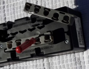
- Prise open the top and bottom covers using the prise points.
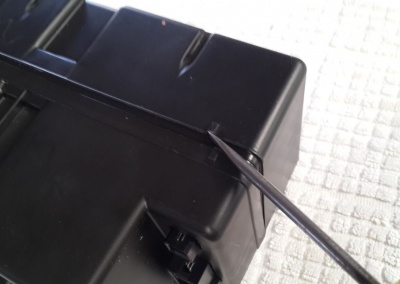
- Remove the white plastic holder at the pump Suction and Discharge Ports. Be careful not to lose the port internal fittings.
- The Port closest to the observer in the next photograph is designated 'X' and is the discharge or +ve pressure port.
- The Port furthest away from the observer in the next photograph is designated 'Y' and is the suction or vacuum or -ve pressure port.
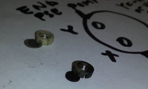
- Carefully note the location and order of the port internal fittings.
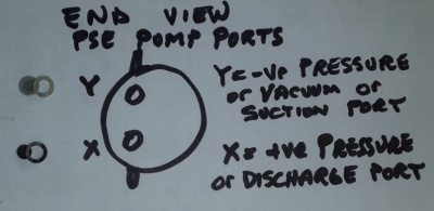
- The discharge or +ve pressure port designated 'X' has a small diameter rubber one way valve and holder fitted into it.
- The suction or vacuum or -ve pressure port designated 'Y' has a small diameter gauze filter and holder fitted into it.
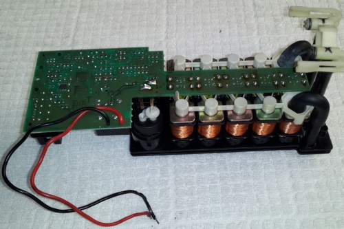
- Unsolder the red and black wires at the pump motor.
- Withdraw the whole internal assembly.
DIY Output Port Leak Repair
If the PSE Pump Output Port has not melted completely and you see small bubbles appearing in the base plate, then it may be possible to prevent it getting any worse. The small pinhole leak shown in the next photo was caused by a burst bubble in the softened plastic base. The position of the leak can be identified by the triangular pattern of dust. This pump was beyond repair as it also had severe internal leakage.
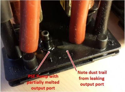
If the leak is not attended to soon it will cause the pump to burn out or be damaged beyond repair.
The real problem in attempting a repair is that it is the pressure port that always fails and it can have up to 110 KPa (16psi) internal pressure which can easily blow off any externally applied glue. The solution is, once the applied glue has set, add a metal tensioner plate with a layer of plasti-bond filler underneath it to take the pressure. One of the cover screws holes can be sacrificed to allow a bolt and nut to hold the metal tensioner plate in place.
Here is the method in detail.
- Apply a dob of super strength super glue (preferably one designed for plastic or difficult to bond materials such as Loctite 406) and allow it to set undisturbed for at least 24 hours.
- Manufacture a metal (aluminium is easier to work than steel but both are suitable) tensioner plate to fit under the adjacent solenoids and around the output port spigot. Make sure it fits well before proceeding. The solenoid valves and the bolt plus the adhesion of the filler prevent the tensioner plate from being blown off.
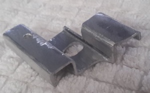
- Drill a 3.5mm hole through the existing cover mounting screw hole and also through the new bracket.
- Clean the area around the output port spigot with suitable degreaser and allow to thoroughly dry.
- Apply a thick layer of Plasti-Bond filler to the area around the output port.
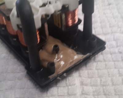
- Immediately place the tensioner plate in place and screw down tightly.
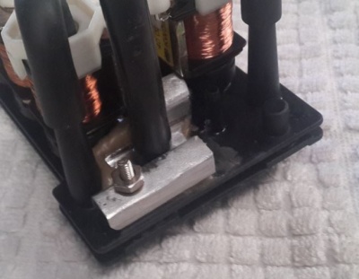
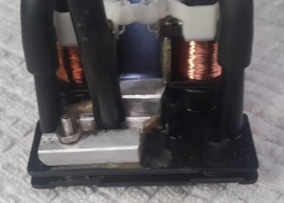
- Place the 10mm diameter output port pipe over the spigot and press down as far as possible.
- Wipe off any excess filler and allow to set.
If you are lucky this should prevent any further blowouts in the plastic due to excess pump heat. To really be sure and to make the design better than the OEM design, add a heat radiator in the Output Port Pneumatic Line. (See below.)
DIY Add a Heat Radiator in Output Port Line
If you want to avoid your pump from damaging the area around the output port due to heat (as shown above), then the addition of a heat transfer radiator in the output pressure pneumatic line will remove some of the excess heat and should avoid any resulting softening, bubbling and subsequent damage to the plastic base plate.
- Wind 1m of 6mm O/D copper pipe around a suitable mandrill of about 50mm diameter to make a coil.
- Shape the ends to allow fitting of suitable pipes with clamps.
- Slightly flare the ends to act as barbs to help prevent the pipe from being blown off.
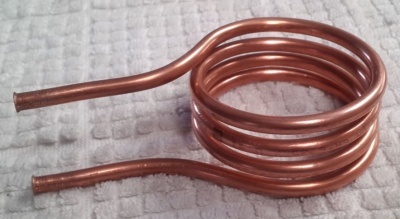
- Insert the heat radiator coil in the output port pneumatic line as shown in the photo.
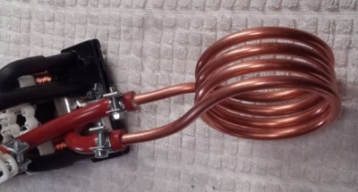
- You must use hose clamps on the output port pneumatic line pressure connections to avoid the internal pressure from blowing the pipes off. (The OEM design obviously relies on the fact that the output port pneumatic pipe is constrained between the electric motor port and the PSE base connection and cannot blow off unless the electric pump is removed.)
- Cut a slot in the PSE Pump Cover to suit the radiator pipes.
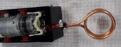
- Also cut a slot in the sound insulating cover to allow the heat radiator to sit outside the PSE Pump. Fortunately there is plenty of space around the PSE Pump in the boot to accommodate the heat radiator. Just make sure it is tied down with plastic ties so that it doesn't create a rattle. Fill any gaps around the pipes in the slot with sound insulating material or silicon. It should be air tight to attenuate as much sound as possible.
Firmly secure the Heat Radiator tubing to the metal panel work using plastic ties to avoid any rattles.
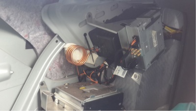
When tested after the pump was made to run by opening and closing the trunk several times, it was found that only one coil of the heat radiator got hot.
DIY Overhaul
A thorough description of a PSE Pump Overhaul by BenzWorld Member evolotion is at;
http://www.benzworld.org/forums/w220-s-class/1563160-pse-central-locking-pump-overhall.html
Lessons Learned
Need to Annotate the Pneumatic Lines
- DO NOT remove any of the Air Lines before ANNOTATING them. The PSE Pump Ports are marked but the Air Lines are not.
Need to Reprogram a New PSE Pump
- A NEW OR USED REPLACEMENT PSE CONTROL MODULE MUST BE PROGRAMMED TO YOUR CAR. This is very, very, very important. The same PSE pump model is used on multiple Benz body styles, and even on the same body style not every car has all of the same options. If it is not programmed (via STAR) it will cause the pump to run much longer than necessary and will burn out the motor.
http://www.benzworld.org/forums/w220-s-class/1654318-pse-soft-close-assist-lessons-learned.html
TIP to Avoid Reprogramming Replacement Pump
You can avoid reprogramming a replacement pump if you swap over the original printed circuit board to the replacement pump. It does require some basic soldering skill. Be careful that you don't splatter solder all over the place and make sure you touch an earthed point before touching any electronic parts to avoid damage due to electrostatic discharge.
Arduino Controlled PSE Pump
If the original printed circuit board is faulty and you have no means to reprogram a replacement, an alternate solution is to create a custom electronic controller using an Arduino.
Do Not Add Additional Lubrication
- Reference BenzWorld Member 'evolotion': The PSE pump is made of a material which is self lubricating. Hence if you were to introduce a liquid lubricant such as WD40 into the motor or pump, any deposits generated during normal operation would stick to the liquid, and before you know it the liquid becomes a paste, to be more precise, a grinding paste.
Fix a Faulty Pump or Pneumatic Lines Promptly
- A PSE pump and associated pneumatic lines with a fault should be repaired promptly. If the pump runs continuously or excessively for too long it will burn out. Note this also applies to a new pump which has not been properly programmed to the car. If it doesn't match the car's equipment it will burn out through excessive operation.
It Is Unsafe to Drive a Car Without a Working PSE Pump
- In the event of an accident the PSE pump unlocks all doors and releases the Child Safety Lock on Rear Doors.
- A non functioning PSE Pump will possibly prevent or at the worst delay first responders from gaining access to a crashed vehicle in the event of an emergency.