Front seats: Difference between revisions
(→Installing seat occupancy sensor emulator: added note on type 2 emulator for facelift W220) |
|||
| (57 intermediate revisions by the same user not shown) | |||
| Line 1: | Line 1: | ||
[[File:W220_prefacelift_front_seat_crosscut.jpg|thumb|none|Pre-[[facelift]] front seat (crosscut).]] | |||
[[File: | {| | ||
|[[File:W220_DAS_EPC_drivers_seat_1.png|thumb|none|EPC: Driver's seat: left seat]] | |||
|[[File:W220_DAS_EPC_drivers_seat_2.png|thumb|none|EPC: Driver's seat: left seat]] | |||
|[[File:W220_DAS_EPC_drivers_seat_3.png|thumb|none|EPC: Driver's seat: right seat]] | |||
|[[File:W220_DAS_EPC_drivers_seat_4.png|thumb|none|EPC: Driver's seat: right seat]] | |||
|} | |||
{| | |||
|[[File:W220_DAS_EPC_drivers_seat_5.png|thumb|none|EPC: Driver's seat: seat adjustment]] | |||
|[[File:W220_DAS_EPC_drivers_seat_6.png|thumb|none|EPC: Driver's seat: coverings, fire extinguisher, first aid box]] | |||
|[[File:W220_DAS_EPC_drivers_seat_7.png|thumb|none|EPC: Driver's seat: Front seat safety belt]] | |||
|} | |||
== Front seat adjustment == | == Front seat adjustment == | ||
| Line 42: | Line 53: | ||
The feature below is deactivated at the factory. If you wish to have it activated, use [[DAS]]. | The feature below is deactivated at the factory. If you wish to have it activated, use [[DAS]]. | ||
The front passenger seat head restraint automatically lowers after a few seconds when the front passenger seat is not occupied. This improves the driver's outward view as well as the forward view from the rear passenger compartment. When the front passenger seat is occupied again, the front passenger seat head restraint returns to the last set position within a few seconds. If the front passenger seat was moved fore or aft while not being occupied, the front passenger seat head restraint returns to a position that corresponds best with the seat’s axial position when the seat is occupied again. | The front passenger seat head restraint automatically lowers after a few seconds when the front passenger seat is not occupied. This improves the driver's outward view as well as the forward view from the rear passenger compartment. When the front passenger seat is occupied again, the front passenger seat head restraint returns to the last set position within a few seconds. If the front passenger seat was moved fore or aft while not being occupied, the front passenger seat head restraint returns to a position that corresponds best with the seat’s axial position when the seat is occupied again. | ||
===Easy-entry/exit feature=== | |||
With the easy-entry/exit feature activated, the steering wheel tilts upwards and the | |||
driver's seat moves to the rear. | |||
This allows easier entry into and exit from the vehicle when the driver’s door is | |||
opened. However, the engine must be turned off. | |||
When the SmartKey is inserted in the starter switch or you have pressed the | |||
KEYLESS-GO start/stop button once and the driver's door is closed, the steering | |||
wheel and the driver’s seat return to their last set positions. | |||
You can activate the following functions: | |||
* Steering column: Only the steering column is adjusted. | |||
* Steering column and seat: The steering column and the seat are adjusted. | |||
The easy-entry/exit feature can be switched on or off in the convenience submenu of the control system. | |||
To cancel seat/steering wheel movement, do one of the following: | |||
* Press the seat adjustment switch | |||
* Move the steering column stalk | |||
* Press the memory button | |||
===Lumbar support=== | |||
For front seats basic lumbar support is available for vehicles without | |||
option code [[Option_codes#404_-_MULTI-CONTOUR_SEAT.2C_FRONT_LEFT|404 - MULTI-CONTOUR SEAT, FRONT LEFT]], | |||
[[Option_codes#405_-_MULTI-CONTOUR_SEAT.2C_FRONT_RIGHT|405 - MULTI-CONTOUR SEAT, FRONT RIGHT]] | |||
and | |||
[[Option_codes#433_-_LEFT_DRIVING_DYNAMICS_SEAT|433 - LEFT DRIVING DYNAMICS SEAT]] | |||
[[Option_codes#434_-_RIGHT_DRIVING_DYNAMICS_SEAT|434 - RIGHT DRIVING DYNAMICS SEAT]]. | |||
On [[rear seats]] basic lumbar support is available in vehicle | |||
with option code [[Option_codes#223_-_REAR_BACK_REST_ADJUSTMENT_AND_HEAD_RESTRAINTS.2C_ELE|223 - REAR BACK REST ADJUSTMENT AND HEAD RESTRAINTS, ELE]]. | |||
You can adjust the contour of the seat's lumbar support to best support your spine. | |||
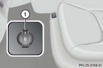
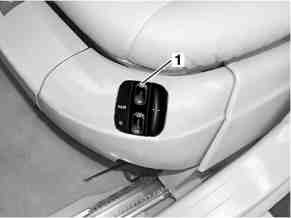
The thumbwheel for the driver's and front passenger's seat are located on the inner side of the seat. | |||
[[File:W220_lumbar_support_thumbwheel.jpg]] | |||
Make sure the ignition is switched on. | |||
Set the lumbar support between 0 and 5. | |||
===Electric seat adjustment (ESA) function=== | ===Electric seat adjustment (ESA) function=== | ||
| Line 304: | Line 354: | ||
on the supply voltage (I = 6.3 A - 16 A), the actuation is terminated immediately. | on the supply voltage (I = 6.3 A - 16 A), the actuation is terminated immediately. | ||
===Front seat adjustment | ===Front seat adjustment control module with memory=== | ||
<!-- GF91.29-P- | <!-- GF91.29-P-2106S, Left front seat adjustment control module with memory, location/task, 22.4.98 | ||
Models 215, 220 --> | |||
<!-- GF91.29-P-2107S, Right front seat adjustment control module with memory location/task, 22.4.98 | |||
Models 215, 220 --> | |||
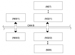
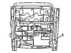
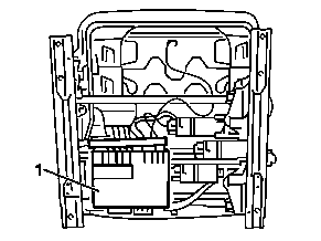
The left/right front seat adjustment control module with memory (N32/1,N32/2) | |||
is located under the seat cushion of the left/right front seat. | |||
{| | {| | ||
| | | | ||
[[File:W220_Left_front_seat_adjustment_control_module_wit_memory.png]] | |||
[[File:W220_Right_front_seat_adjustment_control_module_wit_memory.png]] | |||
| | |||
* | * 1 - Left/right front seat adjustment control module with memory (N32/1,N32/2) | ||
|} | |} | ||
<!-- GF91.29-P-2106-02S Left front seat adjustment control module, with memory, purpose --> | |||
<!-- GF91.29-P-2107-02S, Right front seat adjustment control module with memory, task --> | |||
The left/right front seat adjustment control module with memory (N32/1,N32/2) | |||
connected to the CAN bus has the following tasks : | |||
* Control of the six servo DC motors for the front seat adjustment motor group with memory (M27,M28) | |||
seat | * Position recognition of these motors | ||
* Storage of the seat position by the memory feature as of 1.6.01 expanded by one memory location | |||
* Calling up and approaching seat positions stored previously within the framework of the memory feature | |||
* Approaching the permanently stored seat default settings depending on the longitudinal position of the seat within the framework of the Ergo function up to 31.5.01 | |||
* Control of heated seats/seat ventilation (special equipment) | |||
* Control of the seat belt wearing comfort function | |||
* Monitoring of backrest locking by the left/right front seat backrest release microswitch (S91/3,S92/3), (model 215 only) | |||
In addition the control module is used for contacting of: | |||
* Left/right front seat belt buckle restraint systems switch (S68/3,S68/4) with AB and GUS (only USA) | |||
* Left/right front buckle microswitch (S68/9,S68/10) | |||
* Left side control module - passenger seat occupied and child seat recognition sensor (B48) (right hand steering only) | |||
* Right side control module - occupation recognition and automatic child seat recognition in front passenger's seat (B48) (left hand steering vehicle only) | |||
* Left/right front multicontour backrest control module (N32/15,N32/16) (special equipment) | |||
* Vehicle-sensitive seat belt lock sensor (A60), (model 215 only) | |||
* Left /levtfront seat backrest angle microswitch group (S91/1,S92/1), (model 215 only) | |||
<!-- GF91.29-P-2106-02I Left front seat adjustment control module, with memory, purpose --> | |||
<!-- GF91.29-P-2107-02I, Right front seat adjustment control module with memory, task --> | |||
The signal for the left/right front seat seat occupation is acquired by the | |||
left/right front seat adjustment control module with memory and is | |||
transmitted to the automatic air conditioning control and operating | |||
module via the interior bus (CAN B). | |||
From this information the automatic air conditioning control and | |||
operating module increases, for example, the automatic blower level | |||
of the ventilation depending on the number of people in the vehicle. | |||
air | |||
Furthermore, the blower capacity adjusted in the automatic air | |||
conditioning control and operating module is read in by the left/right front | |||
seat adjustment control module with memory in order to adapt the | |||
seat ventilation by actuating the fans built into the seat | |||
===Front seat adjustment motor group=== | |||
<!-- GF91.29-P-2103-01S Front seat adjustment motor group, location --> | |||
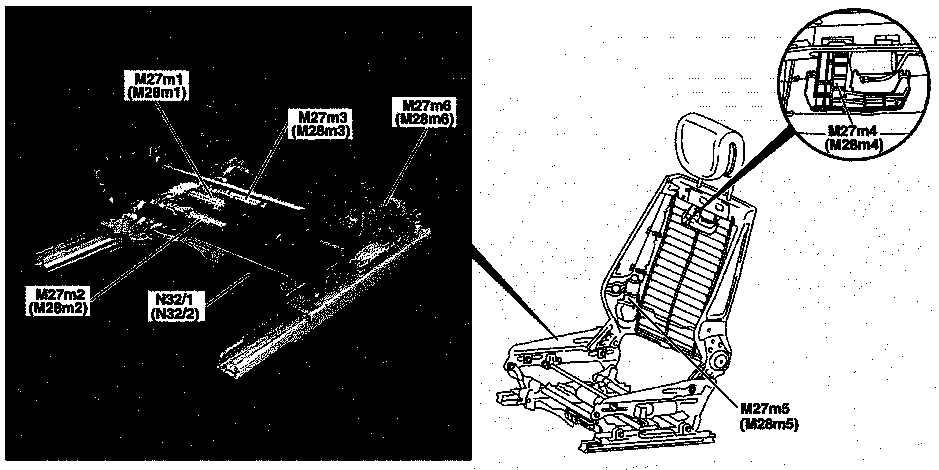
Location of front seat adjustment motor group, shown on model 220: | |||
{| | |||
|[[File:W220_Front_seat_adjustment_motor_group_location.png]] | |||
{| | {| | ||
| | | | ||
* 1 - | Left front seat: | ||
* | * M27 - Left front seat adjustment motor group with memory | ||
* | * M27m1 - Forward/back motor | ||
* M27m2 - Rear raise/lower motor | |||
* M27m3 - Front up/down motor | |||
* M27m4 - Head restraint raise/lower motor | |||
* M27m5 - Backrest forward/back motor | |||
* M27m6 - Seat cushion forward/back motor | |||
* N32/1 - Left front seat adjustment control module with memory | |||
| | |||
Right front seat: | |||
* M28 - Right front seat adjustment motor group with memory | |||
* M28m1 - Forward/back motor | |||
* M28m2 - Rear raise/lower motor | |||
* M28m3 - Front up/down motor | |||
* M28m4 - Head restraint raise/lower motor | |||
* M28m5 - Backrest forward/back motor | |||
* M28m6 - Seat cushion forward/back motor | |||
* N32/2 - Right front seat adjustment control module with memory | |||
|} | |||
|} | |} | ||
<!-- GF91.29-P-2103S, Front seat adjustment motor group, location/function, 9.3.98 | |||
Models 215, 220 --> | |||
The six servo DC motors for adjusting the left/right front seat are actuated by the left front | |||
seat adjustment control module with memory (N32/1)/right front seat adjustment control | |||
module with memory (N32/2). | |||
They have one Hall sensor each for position recognition. | |||
==Multicontour seat function== | |||
Multicontour seats in front are installed in vehicles with option code [[Option_codes#404_-_MULTI-CONTOUR_SEAT.2C_FRONT_LEFT|404 - MULTI-CONTOUR SEAT, FRONT LEFT]] and [[Option_codes#405_-_MULTI-CONTOUR_SEAT.2C_FRONT_RIGHT|405 - MULTI-CONTOUR SEAT, FRONT RIGHT]]. | |||
Vehicles with individual rear seats | |||
option code [[Option_codes#224_-_INDIV.REAR_SEAT_AND_HEAD_RESTRAINTS.2C_ELEC.ADJUSTAB|224 - INDIV.REAR SEAT AND HEAD RESTRAINTS, ELEC.ADJUSTAB]] | |||
have multicontour left/right individual rear seats. | |||
However, compared to front multicontour seats, | |||
the individual rear seats lack air cushions in the shoulder region. | |||
''' | '''Operation of front multicontour backrest''' | ||
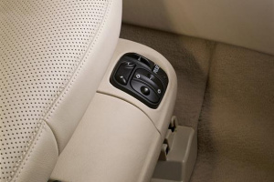
The multicontour | The multicontour backrest has inflatable air cushions built into the seat backrest to provide additional lumbar and side support. | ||
The | The seat backrest cushion height and curvature can be continuously varied with switches on the right side of the seat after | ||
turning the SmartKey in the starter switch to position '''2''' or pressing the KEYLESS-GO start/stop button twice. | |||
[[File:W220_multicontour_backrest_controls.jpg]] | |||
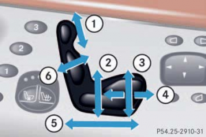
* (1) - Shoulder region support | |||
* | * (2) - Side bolster adjustment | ||
* | * (3) - Massage function (PULSE) | ||
* | * (4) - Lumbar region support | ||
* | |||
Make sure the ignition is switched on. | |||
''' | '''Shoulder region support:''' | ||
Press "+" or "-" on switch (1). The air cushion inflates or deflates. | |||
'''Lumbar region support:''' | |||
The | Press "down" or "up" on rocker switch (4). This selects the air cushion you wish to adjust. | ||
Press "+" or "-" on switch (4). The air cushion inflates or deflates. | |||
''' | '''Side bolsters adjustment:''' | ||
Adjust the side bolsters so that they provide good lateral support using switch (2). | |||
When the engine is turned off, the last cushion setting is retained in memory, | |||
and the cushion is automatically adjusted to this setting when the engine is restarted. | |||
is | |||
''' | '''Massage function (PULSE):''' | ||
You can reduce muscle tension during long trips by periodically using the massage function. | |||
Press button (3). The indicator lamp on button (3) comes on. | |||
The air cushions in the lumbar region inflate and deflate rhythmically. | |||
The massage function switches off automatically after approximately eight minutes. The indicator lamp extinguishes. | |||
'''Multicontour seat function''' | |||
<!-- GF91.25-P-0001S, Multicontour seat (MCS), function, 29.4.98 | |||
MODEL 220 with CODE (404b) Multicontour backrest driver seat | |||
MODEL 220 with CODE (405b) Multicontour backrest passenger seat | |||
MODEL 220 with CODE (224c) Electrically adjustable rear single seats, with seat ventilation, seat heater and memory package | |||
MODEL 220 | |||
with CODE (433) Left dynamic seat, incl. multicontour seat | |||
with CODE (434) Right dynamic seat, incl. multicontour seat | |||
--> | |||
Illustration shows multicontour seat (MCS): | |||
{| | |||
|[[File:W220_multicontour_seat_function.png]] | |||
| | |||
* 1 - Two air cushions for the shoulder region | |||
* 2 - Two air cushions for the side region | |||
* 3 - Three air cushions for the lumbar support region | |||
* 4 - Operating switches | |||
|} | |||
The multicontour backrest of the multicontour seat enables individual | |||
adjustment of the seat backrest by filling and venting a total of seven | |||
air cushions. The contour and surface hardness of the seat backrest | |||
can be adjusted independently of each other. For this (combined into | |||
groups) two air cushions each are used for the shoulder region (1) | |||
and the side region (2), as well as three air cushions for the lumbar | |||
region (3). The filling and emptying of the individual air cushion | |||
groups is controlled either manually, by means of the operating | |||
switch (4) in the seat cushion frame of the respective seat, or | |||
automatically by means of the multicontour backrest control module, | |||
if the function of dynamic lumbar support has been performed. | |||
The storage and calling up of seat backrest adjustments (air cushion | |||
pressure values) is possible with the memory feature. | |||
As of 01/06/2001 the switch group has a different design. | |||
The modifications are shown in the multicontour switch section below. | |||
===Multicontour seat control module=== | |||
<!-- GF91.25-P-2101S, Multicontour seat control module, location/task/design/function, 27.4.98 | |||
MODELS 215, 220 up to 31.8.02 with CODE (404b) Multicontour backrest driver seat | |||
MODELS 215, 220 up to 31.8.02 with CODE (405b) Multicontour backrest passenger seat | |||
MODEL 220 up to 31.8.02 with CODE (224c) Electrically adjustable rear single seats, with seat ventilation, seat heater and memory package | |||
--> | |||
The left front multicontour backrest control module (N32/15)/the right front multicontour | |||
backrest control module (N32/16) is located under the respective seat. | |||
The rear multicontour backrest control module (N32/14) is located under the right half of the rear seat bench. | |||
Apart from the actuation/evaluation | |||
electronics, pressure control valves (one for | |||
each air cushion) are located in all control | |||
modules of the multicontour backrests. The | |||
air cushions are filled and emptied via these | |||
pressure control valves. | |||
The control module reads in the switch | |||
conditions of the switch groups of the | |||
multicontour backrests, detects the air | |||
pressure in the air cushions via piezoresistive | |||
pressure sensors, actuates the pressure | |||
control valves and receives/sends data from/ | |||
to the respective seat control module. | |||
{| | |||
|[[File:W220_left_front_multicontour_backrest_control_module.jpg]] | |||
| | |||
* N32/15 - Left front multicontour backrest control module | |||
* N32/16 - Right front multicontour backrest control module | |||
|} | |||
{| | |||
|[[File:W220_rear_multicontour_backrest_control_module.jpg]] | |||
cushions | | | ||
* N32/14 - Rear multicontour backrests control module | |||
|} | |||
<!-- GF91.25-P-2101-02S, Multi-contour seat control modules, purpose --> | |||
The multi-contour backrest control module is responsible for: | |||
* Inflating and deflating the multi-contour backrest according to the control actions read in from the multi-contour backrest switches | |||
* Control of dynamic lumbar feature, actuated with multi-contour backrest switch ''"PULSE" button'' | |||
* Sensing of actual pressure values in air cushions with piezoresistive pressure sensors | |||
* Generating status data logs on the cushion inflation and transferring these logs to the associated seat control module via a bidirectional, serial interface. | |||
In context with the memory feature: | |||
* Communication with the corresponding control module via interface, particularly regarding storage and recall of stored seat positions | |||
* Setting stored seat positions (pressure values) and other settings when the memory feature is called | |||
===Multicontour seat switches=== | |||
<!-- GF91.25-P-2100S, Multi-contour seat switches, location/purpose/design/function, 27.4.98 | |||
MODEL 215, 220 with CODE (404b) Driver's seat with multi-contour backrest | |||
MODEL 215, 220 with CODE (405b) Passenger seat with multi-contour backrest | |||
MODEL 220 with CODE (224c) Rear bucket seats, electrically adjustable, with seat ventilation, seat heater and memory package | |||
--> | |||
<!-- GF91.25-P-2100-01S, Multi-contour seat switch position--> | |||
The switch train for the front right (S108)/front left (S109)/rear right (S103)/rear left | |||
(S104) multi-contour backrest is located in the corresponding seat, on the outer side of the | |||
seat cushion frame. | |||
{| | |||
|[[File:W220_multicontour_seat_switch_up_to_31-05-2001.jpg|thumb|none|Front left seat up to 31/05/2001.]] | |||
|[[File:W220_front_right_multicontour_seat_switch.jpg|thumb|none|Front right seat as of 01/06/2001.]] | |||
| | |||
* 1 - Switch train for front left multi-contour backrest (S109) | |||
|} | |||
The switch can be used for manually inflating and deflating lumbar | |||
cushion group, side backrest cushions and also, on front seats only, shoulder cushion | |||
group. An additional switch serves for activating and deactivating the dynamic | |||
lumbar adjustment feature. | |||
The switch positions are voltage-coded by means of resistors. | |||
The coded voltages are then read in by the corresponding multi-contour backrest control module. | |||
<!-- GF91.25-P-2100-02S, Multi-contour seat switch structure --> | |||
'''Front seat switch''' | |||
The switch train in the left/right front seat is equipped with a rocker switch for controlling | |||
shoulder cushion and lumbar cushion pulsation. A further rocker switch is used | |||
to control the inflation and deflation of the two seat backrest cushions for lateral support. | |||
A ''"PULSE"'' button is additionally available for switching the dynamic lumbar support on and off. | |||
{| | |||
|[[File:W220_front_seat_switch_train_up_to_31-05-2001.jpg|thumb|none|Front seat switch up to 31/05/2001.]] | |||
|[[File:W220_front_seat_switch_train_as_of_01-06-2001.jpg|thumb|none|Front seat switch as of 01/06/2001.]] | |||
| | |||
* S108 - Switch train for front right multi-contour backrest | |||
* S109 - Switch train for front left multi-contour backrest | |||
* S108s1/S109s1 - Switch for dynamic lumbar support adjustment | |||
* S108s2/S109s2 - Switch for seat cushion side adjustment | |||
* S108s3/S109s3 - Switch for lumbar support adjustment | |||
* S108s4/S109s4 - Switch for shoulder area adjustment | |||
|} | |||
'''Rear seat switch''' | |||
The | The switch train in the left/right rear individual seat is equipped with a rocker switch for | ||
controlling lumbar support cushion pulsation. A further rocker switch is used to control the | |||
inflation and deflation of the two seat backrest cushions for lateral support. A ''"PULSE"'' button is | |||
additionally available for switching the dynamic lumbar support on and off. | |||
{| | |||
|[[File:W220_individual_rear_seat_switch_train_up_to_31-05-2001.jpg|thumb|none|Individual rear seat switch up to 31/05/2001.]] | |||
|[[File:W220_individual_rear_seat_switch_train_as_of_01-06-2001.jpg|thumb|none|Individual rear seat switch as of 01/06/2001.]] | |||
| | |||
* S103 - Switch for rear right multi-contour backrest | |||
* S104 - Switch for rear left multi-contour backrest | |||
* S103s1/S104s1 - Switch for dynamic lumbar support adjustment | |||
* S103s2/S104s2 - Switch for seat cushion side adjustment | |||
* S103s3/S104s3 - Switch for lumbar support adjustment | |||
|} | |||
===Adjust front multicontour seats function=== | ===Adjust front multicontour seats function=== | ||
| Line 569: | Line 702: | ||
air cushions as per the stored values. | air cushions as per the stored values. | ||
As of 01/09/2002 codes 344 and 343 | |||
As of 01/09/2002 the left front dynamic seat control module (N32/19) | the left front dynamic seat control module (N32/19) | ||
and right front dynamic seat control module (N32/22) are | and right front dynamic seat control module (N32/22) are | ||
responsible for the memory feature. | responsible for the memory feature. | ||
===Manual | ===Manual adjustment of air cushions in the multicontour seat=== | ||
<!-- GF91.25-P-2000S, Manual filling/emptying of air in the air cushions in the multicontour seat, function, 29.4.98 | <!-- GF91.25-P-2000S, Manual filling/emptying of air in the air cushions in the multicontour seat, function, 29.4.98 | ||
MODEL 220 with CODE (404b) Multicontour backrest driver seat | MODEL 220 with CODE (404b) Multicontour backrest driver seat | ||
| Line 587: | Line 720: | ||
* Circuit 15 ON | * Circuit 15 ON | ||
The air cushions of the multicontour backrest can be adjusted | The air cushions of the multicontour backrest can be adjusted | ||
manually via the right rear/left rear multicontour backrest switch | manually via the right rear/left rear multicontour backrest switch | ||
| Line 604: | Line 736: | ||
module. | module. | ||
{| | |||
|[[File:W220_front_seat_switch_train_up_to_31-05-2001.jpg|thumb|none|Front seat switch train up to 31/05/2001.]] | |||
and | |[[File:W220_front_seat_switch_train_as_of_01-06-2001.jpg|thumb|none|Front seat switch train as of 01/06/2001.]] | ||
|} | |||
'''Manual adjustment of the shoulder region (up to 31/05/2001)''' | |||
Manual adjustment of the shoulder region by switch for the | |||
shoulder region (S103s4/S104s4). | |||
For driver's and front passenger's seat only. | |||
This provision for adjustment is not realized for the individual rear seats. | |||
{| | {| | ||
|[[File:W220_manual_adjustment_of_the_shoulder_region.png]] | |[[File:W220_manual_adjustment_of_the_shoulder_region.png|thumb|none|Manual adjustment of the shoulder region.]] | ||
| | | | ||
* A - Top half of the switch | * A - Top half of the switch | ||
* B - Bottom half of the switch | * B - Bottom half of the switch | ||
|} | |} | ||
Pressing the bottom half of the switch: | |||
Air cushions 1 and 2 of the shoulder region are filled in sequence | Air cushions 1 and 2 of the shoulder region are filled in sequence | ||
from top to bottom up to the maximum pressure and then emptied | from top to bottom up to the maximum pressure and then emptied | ||
| Line 629: | Line 762: | ||
air cushion 2 is at minimum pressure. | air cushion 2 is at minimum pressure. | ||
Pressing the top half of the switch: | |||
The air cushions are filled in the reverse order, thus from the bottom | The air cushions are filled in the reverse order, thus from the bottom | ||
upwards and then emptied (see above). | upwards and then emptied (see above). | ||
The transfer pressure p üb and the dwell period tv are adjustable. | The transfer pressure p üb and the dwell period tv are adjustable. | ||
'''Manual adjustment of the shoulder region (as of 01/06/2001)''' | |||
When the rocker switch is pressed towards "+" or "-" the backrest | When the rocker switch is pressed towards "+" or "-" the backrest | ||
| Line 648: | Line 774: | ||
cushions. | cushions. | ||
This provision for adjustment is not realized for the individual rear | This provision for adjustment is not realized for the individual rear seats. | ||
'''Manual adjustment of the lumbar support region (up to 31/05/2001)''' | |||
Manual adjustment of the lumbar support region by | |||
the rear left/right lumbar support adjustment switch (S103s3/S104s3) | |||
and front right/left lumbar support adjustment switch (S108s3/S109s3). | |||
{| | {| | ||
|[[File:W220_manual_adjustment_of_the_lumbar_support_region_of_the_front_rear_seat.png]] | |[[File:W220_manual_adjustment_of_the_lumbar_support_region_of_the_front_rear_seat.png|thumb|none|Manual adjustment of the lumbar support region.]] | ||
| | | | ||
* A - Top half of the switch | * A - Top half of the switch | ||
| Line 659: | Line 789: | ||
|} | |} | ||
Pressing the bottom half of the switch: | |||
Air cushions 3, 4, 5 of the lumbar support region are filled from top to | |||
Pressing the bottom half of the switch | |||
bottom up to the maximum pressure and then emptied again down to | bottom up to the maximum pressure and then emptied again down to | ||
the minimum pressure. The process stops as soon as air cushion 5 | the minimum pressure. The process stops as soon as air cushion 5 | ||
has reached the minimum pressure. | has reached the minimum pressure. | ||
'''Manual | Pressing the top half of the switch: | ||
The air cushions are filled in the sequence 5, 4, 3, so from top to | |||
bottom and then emptied again (see above). | |||
The transfer pressure p üb and the dwell period tv are adjustable. | |||
'''Manual adjustment of the lumbar support region (as of 01/06/2001)''' | |||
When the cross rocker is pressed towards "+" or "-" the backrest contour changes in the | When the cross rocker is pressed towards "+" or "-" the backrest contour changes in the | ||
lumbar support region by filling/emptying the air cushion which is | lumbar support region by filling/emptying the air cushion which is | ||
| Line 680: | Line 809: | ||
When the cross rocker of the bottom half of the switch is pressed the | When the cross rocker of the bottom half of the switch is pressed the | ||
backrest contour in the lumbar support region is changed sequentially. | backrest contour in the lumbar support region is changed sequentially. | ||
Only one air cushion is actuated actively in this process. | |||
When the cross rocker of the top half of the switch is pressed the | |||
actively in this process. | sequence is the same as when the bottom half of the switch is | ||
pressed, only in the reverse order. | |||
===Dynamic lumbar support of multicontour backrest=== | |||
<!-- GF91.25-P-2001S, Dynamic filling/emptying of air in the air cushions in the multicontour seat, function, 29.4.98 | |||
MODEL 220 with CODE (404b) Multicontour backrest driver seat | |||
MODEL 220 with CODE (405b) Multicontour backrest passenger seat | |||
MODEL 220 with CODE (224c) Electrically adjustable rear single seats, with seat ventilation, seat heater and memory package | |||
MODEL 220 | |||
with CODE (433) Left dynamic seat, incl. multicontour seat | |||
with CODE (434) Right dynamic seat, incl. multicontour seat | |||
--> | |||
In order to prevent stresses in the back on longer journeys, the | |||
multicontour backrest is equipped with the dynamic lumbar support | |||
function. The function is controlled in the relevant seat by the | |||
multicontour backrest control module. It is triggered by pressing ''"PULSE" button'' on | |||
the dynamic lumbar support adjustment switch (S103s1/S104s1/S108s1/S109s1) | |||
in the left rear/right rear multicontour backrest | |||
switch group (S103, S104) and right front/left front multicontour | |||
backrest switch group (S108, S109). | |||
Lumbar support: curvature of spine in lumbar region. | |||
Starting with the air cushion which is currently active the pulsation | |||
occurs alternately in the two lumbar support cushions in the | |||
sequence lower and upper lumbar (sequence is parameterizable). | |||
Filling starts with the active lumbar support cushion up to the next | |||
pressure level, unless the upper pressure level has already been | |||
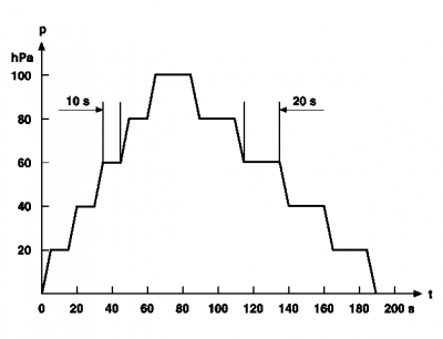
reached or exceeded. Each air pressure adjustment is held for | |||
approx. 10 seconds before the next condition is assumed. After | |||
approx. 8 minutes the program is terminated automatically and the | |||
original air cushion pressures are reproduced. | |||
Illustration shows function sequence for dynamic lumbar support: | |||
[[File:W220_function_sequence_for_dynamic_lumbar_support.png|400px]] | |||
First of all the three lumbar support air cushions of the multicontour | |||
backrest are emptied. After this the center air cushion is filled in | |||
stages up to the maximum pressure and then emptied again down to | |||
The | the minimum pressure (see Figure). This process (cycle) is repeated | ||
for a second time. After this the function is terminated by the control module. | |||
The function can be terminated at any time by pressing the switch again. | |||
== | === Retrofitting multicontour backrest === | ||
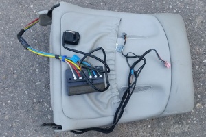
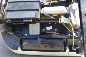
Multicontour backrest option can be easily retrofitted. The only parts needed are multicontour backrest, multicontour control module and switch from the donor vehicle. | |||
For installation instructions on [[facelift]] vehicle see the instructions below. | |||
Installation may require to modify the fitting on the overpressure reservoir. | |||
{| | {| | ||
|[[File: | |[[File:W220_drivers_side_seat_multicontour_backrest.jpg|thumb|none|Multicontour backrest, control module and switch for left (driver's) front seat with heating and ventilation]] | ||
| | |[[File:W220_drivers_left_front_seat_without_multicontour_backrest.jpg|thumb|none|Front left seat without multicontour backrest control module]] | ||
|[[File:W220_drivers_left_front_seat_multicontour_backrest_control_module_connections.jpg|thumb|none|Installation of multicontour backrest control module]] | |||
|[[File:W220_drivers_left_front_seat_multicontour_backrest_control_module.jpg|thumb|none|Front seat with multicontour backrest module installed]] | |||
|} | |} | ||
== Dynamic seat function == | |||
# | Dynamic seat (drive-dynamic seat) function available as of 01/09/2002 | ||
# | on vehicles equipped with option code | ||
[[Option_codes#433_-_LEFT_DRIVING_DYNAMICS_SEAT|433 - LEFT DRIVING DYNAMICS SEAT]] | |||
and | |||
[[Option_codes#434_-_RIGHT_DRIVING_DYNAMICS_SEAT|434 - RIGHT DRIVING DYNAMICS SEAT]]. | |||
<!-- operators manual --> | |||
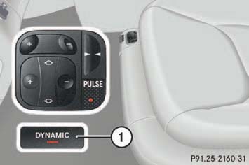
The drive-dynamic seat automatically adjusts the lateral support provided by the seat backrest to your driving style. | |||
[[File:W220_drive-dynamic_seat.jpg]] | |||
To activate drive-dynamic function press button (1). | |||
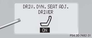
The indicator lamp in the switch comes on and the following message appears in the multifunction display for five seconds: | |||
[[File:W220_driv_dyn_seat_adj_driver.jpg]] | |||
The drive-dynamic seat electronically controls the air pressure in the air chambers of the seat backrest side bolsters. | |||
This function improves driving comfort and pleasure. | |||
You can adjust the characteristics of the drive-dynamic seat using the control system. | |||
<!-- GF91.25-P-0001S --> | |||
<!-- | |||
--> | |||
Illustration shows Dynamic seat (FDS) as of 01/09/2002 with codes 433 and 434: | |||
{| | {| | ||
|[[File: | |[[File:W220_dynamic_seat_facelift.jpg]] | ||
| | | | ||
* 1 - | * 1 - Air cushion for the shoulder region (coupled) | ||
* 2 - | * 2 - Air cushion for the respective side region | ||
* 3 - | * 3 - Air cushion for the upper and lower lumbar support region | ||
|} | |||
|} | |||
All the following provisions for adjustment are explained on the | |||
driver's seat and also apply to the front passenger's seat. | |||
The dynamic seat comprises the functions: | |||
* Memory multicontour backrest (MMKL) | |||
* Dynamic side support | |||
'''Memory multicontour backrest (MMKL)''' | |||
The multicontour backrests enable individual adjustment of the | |||
respective seat backrest by filling and emptying up to three air | |||
cushion groups: | |||
* Air cushion for the upper and lower shoulder region | |||
* Air cushion for the respective side region | |||
* Air cushion for the upper and lower lumbar support region | |||
The "Dynamic lateral support" function is switched on or off by | |||
of the | pressing the FDS ''"DYNAMIC"'' button and is controlled by the left front dynamic | ||
seat control module (N32/19). If the function is activated, this is | |||
displayed by an LED in the FDS ''"DYNAMIC"'' button. The left front dynamic seat | |||
control module (N32/19) adjusts after that a corresponding basic | |||
pressure in the lateral support cushions and, when cornering, | |||
ensures better retention in the lateral support by temporarily adding | |||
pressure to the lateral support cushions on the outside of the curve. | |||
This essentially happens as a function of the instantaneous speed | |||
and the lateral acceleration. This information comes from the traction | |||
systems control module (N47) and is transmitted by central gateway | |||
control module (N93) from CAN-C (engine compartment) to CAN-B | |||
(interior). If the data for the FDS function fail for more than 2 | |||
seconds, the function is switched off and remains switched off. | |||
The extent and speed with which the lateral support cushions for the | |||
driver's and front passenger's seat are filled can be adjusted via the | |||
second operating level of the instrument cluster (A1). | |||
'''Priority sequence of the functions''' | |||
The priorities are set in the sequence: | |||
* Priority 1 Lumbar support | |||
* Priority 2 Shoulder region (not for individual rear seats) | |||
* Priority 3 Lateral support | |||
* Priority 4 Dynamic lumbar support and dynamic lateral support (front seats only) | |||
When pressing multiple rocker switches at the same time, only the | |||
* 1 | adjustment movement with the highest priority is executed. | ||
* 2 | |||
* 3 | |||
* 4 | |||
'''Abort criteria''' | |||
All functions are interrupted if there is overvoltage or undervoltage. | |||
The relevant function is not performed if a valve has overheated or | |||
there is a leakage fault. | |||
'''Limit stop emptying''' | |||
If the end point is reached after the lumbar support wave has | |||
passed, the inactive air cushion is emptied for as long as the switch | |||
is pressed, but for a maximum period of 1 minute. | |||
'''Control functions''' | |||
The adjusted specified pressures of the individual cushion areas are | |||
controlled by the left front dynamic seat control module (N32/19) and | |||
right front dynamic seat control module (N32/22) in each case in a | |||
manner which is unnoticeable for the customer provided that the | |||
function conditions for manual adjustment are met. | |||
The contour and surface hardness of the seat backrest can be | |||
adjusted manually via the: | |||
* Switch group for right front multicontour backrest (S108) | |||
* Switch group for left front multicontour backrest (S109) | |||
* the "dynamic lumbar support" function. | |||
'''Dynamic lateral support (driver's/front passenger's seat)''' | |||
Function requirements: | |||
* | * Circuit 15R ON | ||
* | * Circuit 15 ON | ||
* No undervoltage or overvoltage | |||
* No overtemperature sensor | |||
* No leakage fault in the lateral support region | |||
Sport (stage 1): Extra pressure is applied more quickly and more intensely to the | |||
lateral support cushions on the outside of the curve. | |||
Comfort (stage 2): Extra pressure is applied slowly and less intensely to the lateral | |||
support cushions on the outside of the curve. | |||
Definitively the following control modules are involved in the dynamic seat: | |||
* left front dynamic seat control module (N32/19) | |||
* right front dynamic seat control module (N32/22) | |||
* central gateway control module (N93) | |||
* traction systems control module (N47) | |||
'''Background functions''' | |||
In the lumbar support region the cushions are arranged overlapping | |||
and consequently coupled in their function during the wave | |||
sequence. As only one air cushion is active in each case, the | |||
adjacent cushions are considered as not active i.e. empty. The | |||
following background functions are necessary to ensure this. | |||
'''Idle time emptying (optional)''' | |||
While the pressure is kept constant in the active air cushion | |||
(residence time), the adjacent non-active air cushions are emptied. | |||
'''Backgrounds emptying''' | |||
== | If the active air cushion is emptied, then the residual pressure in the | ||
<!-- | adjacent non-active air cushions is also reduced, as soon as the air | ||
cushions have the same pressure. | |||
The subsequent regulation follows, for example, in the event of | |||
pressure deviations caused by: | |||
* The respective person sitting in or leaning on the seat | |||
* Leakage in the seat inflators | |||
* Temperature changes caused by heated seats, insolation, air conditioning and user warmth | |||
Sudden changes in pressure which arise due to the person sitting in | |||
on leaning on the seat are adjusted immediately and in a comfort- | |||
orientated manner. The control parameters that are listed can be | |||
programmed using diagnosis. | |||
===Dynamic seat control module=== | |||
<!-- GF91.25-P-2105S, Dynamic seat control module location/task, 3.7.02 | |||
MODELS 215, 220 | |||
with CODE (433) Left dynamic seat, incl. multicontour seat | |||
with CODE (434) Right dynamic seat, incl. multicontour seat | |||
--> | --> | ||
The left front dynamic seat control module | |||
(N32/19) and right front dynamic seat control | |||
module (N32/22) is located in the respective | |||
seat backrests on the driver's/front passenger's side. | |||
{| | {| | ||
|[[File: | |[[File:W220_Dynamic_seat_control_module_location.jpg]] | ||
| | | | ||
* 1 - | * 1 - Air cushion for the shoulder region (coupled) | ||
* 2 - | * 2 - Air cushion for the respective side region | ||
* 3 - Left | * 3 - Air cushion for the upper and lower lumbar support region | ||
* | * N32/19 - Left front dynamic seat control module | ||
* | * N32/22 - Right front dynamic seat control module | ||
* | |} | ||
* | |||
* | <!-- GF91.25-P-2105-01S, Dynamic seat control module location --> | ||
* | Tasks: | ||
* To fill and empty the multicontour backrest in accordance with the requirements read in by the switch | |||
* Control of dynamic lumbar support, triggered by the multicontour backrest switch with the inscription: "PULSE" | |||
* Control of dynamic lateral support triggered by the "DYNAMIC" switch | |||
* Detection of the actual pressure values of the air cushions by piezoresistive pressure sensors and keeping these pressures constant | |||
* Reading in the voltage-coded MMKL adjusting switch and the DYNAMIC switch | |||
* Communication with the interior CAN via the respective seat control module | |||
* Adjusting the stored pressure values when calling up the memory feature and storing the actual contours | |||
* Cutout of the respective function if the pressure control valve responsible has overheated | |||
===Dynamic seat switch=== | |||
<!-- GF91.25-P-2110S, Dynamic seat switch, location/task, 23.5.02 | |||
MODEL 220 as of 1.9.02 | |||
with CODE (433) Left dynamic seat, incl. multicontour seat | |||
with CODE (434) Right dynamic seat, incl. multicontour seat | |||
--> | |||
The right/left front DS [FDS] switch group (S108/1,S109/1) in each case is located | |||
under the front multicontour backrest switch group on the seat cushion. | |||
The switch turns the dynamic lateral support function on and off. | |||
{| | {| | ||
|[[File: | |[[File:W220_Dynamic_seat_switch.jpg]] | ||
| | | | ||
* 1 - | * 1 - Air cushion for the shoulder region (coupled) | ||
* | * 2 - Air cushion for the respective side region | ||
* | * 3 - Air cushions for the upper and lower lumbar support region | ||
* | * S108 - Switch group for the right front multicontour backrest | ||
* | * S109 - Switch group for the left front multicontour backrest | ||
* | * S108/1 - Right front vehicle dynamic system switch | ||
* S109/1 - Left front vehicle dynamic system switch | |||
|} | |} | ||
===Manual adjustment of air cushions in the dynamic multicontour seat=== | |||
All the following provisions for adjustment are explained on the | |||
driver's seat and also apply to the front passenger's seat. | |||
'''Manual adjustment of the shoulder region as of 01/09/2002 with codes 433 and 434''' | |||
Air cushions 1 and 2 of the shoulder region are coupled and are | |||
adjusted with the shoulder region adjustment switch (S109s4). | |||
When the rocker switch is pressed towards "+" or "-" the backrest | |||
contour in the shoulder region is changed by filling/emptying the air | |||
cushions. | |||
'''Manual Adjustment of the lumbar support region as of 01/09/2002 with codes 433 and 434''' | |||
The lumbar support region of the seat is operated by the lumbar | |||
support adjustment switch (S109s3). | |||
When the cross rocker is pressed towards "+" or "-" the backrest contour changes in the | |||
lumbar support region by filling/emptying the air cushion which is | |||
currently active. | |||
When the cross rocker of the bottom half of the switch is pressed the | |||
backrest contour in the lumbar support region is changed sequentially. | |||
First, the lower air cushion is filled/emptied again and | |||
then the upper air cushion is filled. Only one air cushion is actuated | |||
actively in this process. This sequence starts with the air cushion | |||
which has just become active. | |||
When the cross rocker of the top half of the switch is pressed the | |||
sequence is the same as when the bottom half of the switch is | |||
pressed, only in the reverse order. | |||
The upper air cushion is emptied first and then the lower air cushion | |||
is filled. | |||
===Dynamic lumbar support=== | |||
<!-- GF91.25-P-2001S--> | |||
All the following provisions for adjustment are explained on the | |||
driver's seat and also apply to the front passenger's seat. | |||
In order to prevent stresses in the back on longer journeys, the | |||
dynamic seat multicontour backrest is equipped with the dynamic lumbar support | |||
function. The function is controlled in the relevant seat by the | |||
multicontour backrest control module. | |||
It is triggered by pressing ''"PULSE" button'' on | |||
the dynamic lumbar support adjustment switch (S103s1/S104s1/S108s1/S109s1) | |||
in the left rear/right rear multicontour backrest | |||
switch group (S103, S104) and right front/left front multicontour | |||
backrest switch group (S108, S109). | |||
Lumbar support: curvature of spine in lumbar region. | |||
Starting with the air cushion which is currently active the pulsation | |||
occurs alternately in the two lumbar support cushions in the | |||
sequence lower and upper lumbar (sequence is parameterizable). | |||
Filling starts with the active lumbar support cushion up to the next | |||
pressure level, unless the upper pressure level has already been | |||
reached or exceeded. Each air pressure adjustment is held for | |||
approx. 10 seconds before the next condition is assumed. After | |||
approx. 8 minutes the program is terminated automatically and the | |||
original air cushion pressures are reproduced. | |||
Illustration shows function sequence of dynamic lumbar support as of 01/09/2002 with codes 433 and 434: | |||
{| | {| | ||
|[[File: | |[[File:W220_function_sequence_of_dynamic_lumbar_support_code_443_434.jpg]] | ||
| | | | ||
* | * A - Upper lumbar support | ||
* | * B - Lower lumbar support | ||
|} | |||
The function is controlled by the left front dynamic seat control | |||
module (N32/19). The program is started and stopped by the | |||
* | dynamic lumbar support adjustment switch (S109s1) ''"PULSE" button''. The active | ||
* | function is displayed by illuminating the LED in the switch. | ||
* | After the switch is pressed, first the air pressures of the air cushion in | ||
* | the lumbar support region are stored by the left front dynamic seat | ||
control module (N32/19). | |||
==Remove/install front seat belt buckle (up to 31/08/2002)== | |||
<!-- AR91.40-P-1515M, Remove/install belt buckle (front seat), 12.12.97 | |||
MODELS 220.0 /1 up to 31.8.02 --> | |||
{| | |||
|[[File:W220_Remove_install_front_seat_belt_buckle_up_to_31-08-2002_1.jpg]] | |||
|[[File:W220_Remove_install_front_seat_belt_buckle_up_to_31-08-2002_2.jpg]] | |||
| | |||
* 1 - Seatbelt buckle | |||
* 2 - Bolt | |||
* N32/1 - Left front seat adjustment control unit with memory | |||
* N32/2 - Right front seat adjustment control unit with memory | |||
* Arrow - plug socket | |||
|} | |} | ||
# | # Remove front seat | ||
# | # Open cable straps of seat belt buckle switch cable on underside of seat | ||
# Remove coupling (arrow) from left (N32/1) and right (N32/2) front seat adjustment control unit with memory | |||
# Unscrew seat belt buckle screw (2) and remove seat belt buckle (1) | |||
# Install in the reverse order | |||
# | |||
# Install in the reverse order | |||
Torque | Torque specifications: | ||
* Screw/nut on front seat belt buckle: 30 Nm | |||
* Screw/nut on front seat belt | |||
==Remove/install front seat belt buckle (as of 01/09/2002)== | |||
<!-- AR91.40-P-1515MB, Remove/install belt buckle (front seat), 25.11.02 | |||
==Remove/install seat belt ( | MODELS 220.0 /1 as of 1.9.02 with CODE (803) Model year 2003 | ||
<!-- AR91.40-P- | --> | ||
MODELS 220.0 /1 | |||
{| | {| | ||
|[[File: | |[[File:W220_Remove_install_front_seat_belt_buckle_as_of_01-09-2002.jpg]] | ||
| | | | ||
* 1 - Belt end fitting | * 1 - Nut | ||
* 2 - Upper belt guide fitting | * 2 - Seatbelt buckle | ||
* 3 - Automatic belt retractor | * 3 - Wiring harness | ||
* N32/1 - Left front seat adjustment control unit with memory | |||
* N32/2 - Right front seat adjustment control unit with memory | |||
* R46 - Driver-side buckle ETR | |||
* R46/1 - Passenger-side buckle ETR | |||
* X28/34 - 2-pin driver seat buckle emergency tensioning retractor connector separating point | |||
* X28/35 - 2-pin front passenger seat buckle emergency tensioning retractor connector separating point | |||
|} | |||
# Switch ignition off, withdraw ignition key | |||
# Switch off engine, remove transmitter card from the vehicle (with keyless go code 889). Keep transmitter key outside transmission range. | |||
# Remove front seat | |||
# Unscrew nut (1) from seat belt buckle (2) | |||
# Disconnect and expose wiring harness (3) with yellow connectors (see arrow and magnification) to left (N32/1) and right (N32/2) front seat adjustment control unit with memory and to 2-pin driver (X28/34) and front passenger (X28/35) seat buckle emergency tensioning retractor connector separation point | |||
# Remove seat belt buckle (2) with driver (R46) and front passenger (R46/1) buckle ETR (R46) from front seat. If seat belt buckle (2) with driver (R46) and front passenger (R46/1) buckle ETR is replaced, the defective part must be properly disposed. | |||
Torque specifications: | |||
* Screw/nut on front seat belt buckle: 30 Nm | |||
{| | |||
|[[File:W220_drivers_left_front_seat_belt_buckle.jpg|thumb|none|Seat belt buckle before explosion]] | |||
|[[File:W220_drivers_left_front_seat_belt_buckle_after_explosion.jpg|thumb|none|Seat belt buckle after explosion]] | |||
|} | |||
==Remove/install front seat belt (up to 31/08/2002)== | |||
<!-- AR91.40-P-1010M, Remove/install seat belt (front seat), 18.12.97 | |||
MODELS 220.0 /1 up to 31.8.02 --> | |||
{| | |||
|[[File:W220_Remove_install_seat_belt_front seat_pre-facelift.png]] | |||
| | |||
* 1 - Belt end fitting | |||
* 2 - Upper belt guide fitting | |||
* 3 - Automatic belt retractor | |||
* R12/1 - Driver ETR [GUS] ignition squib | * R12/1 - Driver ETR [GUS] ignition squib | ||
* R12/2 - Passenger ETR [GUS] ignition squib | * R12/2 - Passenger ETR [GUS] ignition squib | ||
| Line 1,133: | Line 1,256: | ||
* Screw on front automatic belt reel: 30 Nm | * Screw on front automatic belt reel: 30 Nm | ||
== | ==Remove/install front seat belt (as of 01/09/2002)== | ||
<!-- AR91.40-P- | <!-- AR91.40-P-1010MB, Remove/install seat belt (front seat), 25.11.02 | ||
MODELS 220.0 /1 as of 1.9.02 with CODE (803) Model year 2003 | |||
--> | --> | ||
{| | {| | ||
|[[File: | |[[File:W220_Remove_install_seat_belt_front seat_facelift.jpg]] | ||
| | | | ||
* 1 - Belt | * 1 - Upper belt guide fitting | ||
* | * 2 - Nut | ||
* | * 3 - Cover | ||
* | * 4 - Belt end fitting | ||
* 5 - Bolt | |||
* 6 - Bowden cable | |||
* 7 - Bolt | |||
* 8 - Torx screws | |||
* A76 - Left front reversible emergency tensioning retractor [RevETR-LF] | |||
* A76/1 - Right front reversible emergency tensioning retractor [RevETR-RF] | |||
|} | |} | ||
# | # Move front seat as far forward as possible with backrest upright | ||
# Switch ignition off, withdraw ignition key | |||
# Switch engine off, remove transmitter key from vehicle. With [[KEYLESS-GO]] code 889 keep transmitter key outside transmission range. | |||
# [[Remove/install_paneling_on_B-pillar|Remove paneling on B-pillar]] | # [[Remove/install_paneling_on_B-pillar|Remove paneling on B-pillar]] | ||
# | # Remove cover (3) of belt end fitting (4) and undo screw (5) | ||
# | # Unscrew screw (2) from seat belt guide bracket (1) | ||
# | # Unhook Bowden cable (6) on cover plate (see magnifying glass at bottom right) | ||
# Undo | # Undo TORX screw (8, 4 pieces) on cover plate. Installation: Tighten screw (7) to torque rating. | ||
# Undo screw (2, | # Undo screw (7) from cover plate. Installation: Tighten screw (7) finger-tight only to cover plate. | ||
# Detach 6-pin coupling and 2-pin coupling (see arrows) of left front reversible emergency tensioning retractor (A76), and right front reversible emergency tensioning retractor | |||
# (A76/1) Remove left front reversible emergency tensioning retractor (A76), and left front reversible emergency tensioning retractor (A76/1). Installation: Note different version (left/right) of seat belt emergency tensioning retractor and correct seating in cover plate. Noises from the automatic belt reel when rolling up belt are normal. The only available response to negative customer feedback regarding unacceptable noise levels is to replace the seat belt assembly with emergency tensioning retractor in its entirety. On no account should oil or grease be used to help eliminate noise. Automatic belt retractors that have been opened are no longer under warranty! | |||
# Install in the reverse order | # Install in the reverse order | ||
# Carry out diagnosis | |||
Torque specification: | Torque specification: | ||
* Belt end fitting screw: 30 Nm | |||
* Screw/nut on front seat belt guide bracket: 30 Nm | * Screw/nut on front seat belt guide bracket: 30 Nm | ||
* Screw on front automatic belt | * Screw on front automatic belt reel: 30 Nm | ||
* Bolt, emergency tensioning retractor cover plate to B-pillar: 10 Nm | |||
[[File:W220_right_front_reversible_emergency_tensioning_retractor.jpg|thumb|none|Right front reversible emergency tensioning retractor unscrewed.]] | |||
==Remove/install front seat | ==Remove/install front seat belt height adjustment mechanism== | ||
<!-- AR91. | <!-- AR91.40-P-1100M, Seat belt height adjustment mechanism (front seat) removal and installation, 21.1.98 | ||
Models 220.0 /1 | |||
--> | --> | ||
{| | {| | ||
|[[File: | |[[File:W220_seat_belt_height_adjustment_mechanism_front_seat_removal_and_installation.jpg]] | ||
| | | | ||
* 1 - | * 1 - Belt height adjuster | ||
* 2 - Bolt | * 2 - Bolt | ||
* 3 - | * 3 - Bowden cable | ||
* 4 - | * 4 - Nut | ||
|} | |||
# Remove front seat | |||
* | # [[Remove/install_paneling_on_B-pillar|Remove paneling on B-pillar]] | ||
* | # Unclip Bowden cable (3) using Omega clip | ||
# Unclip Bowden cable (3) from deflection in cable duct. Lift floor lining at left front until the deflection for the Bowden cable (3) in the cable duct can be easily accessed. | |||
# Disassemble the Bowden cable (3) up to the belt height adjuster (1) | |||
# Undo nut from seat belt guide bracket (4) | |||
# Undo screw (2, 2 pieces) on belt height adjuster (1) | |||
# Install in the reverse order | |||
Torque specification: | |||
* Screw/nut on front seat belt guide bracket: 30 Nm | |||
* Screw on front automatic belt height adjuster: 25 Nm | |||
==Remove/install front seat backrest seat-back lining== | |||
<!-- AR91.10-P-1910E, Remove/install front seat backrest seat-back lining, 22.12.93 | |||
MODELS 202, 210, 220 | |||
--> | |||
{| | {| | ||
|[[File: | |[[File:W220_Remove_install_front_seat_backrest_seat-back_lining.png]] | ||
| | | | ||
* 1 - | * 1 - Bolts | ||
* 2 - | * 2 - Seat-back lining | ||
|} | |} | ||
# | # Slide the front seat forwards with the longitudinal adjustment mechanism | ||
# | # Slide backrest forwards with the inclination adjustment mechanism | ||
# | # Unscrew screws (1) | ||
# Pull seat-back lining (2) down and take off. Installation: slide seat-back lining into top of backrest. | |||
# Install in the reverse order | # Install in the reverse order | ||
Backrest seat-back lining is interchangeable between left and right seat backrest. | |||
{| | {| | ||
|[[File: | |[[File:W220_seat_backrest_lining_screw.jpg|thumb|none|Seat backrest lining screw.]] | ||
| | |[[File:W220_facelift_front_seat_backrest_lining_inside.jpg|thumb|none|Backrest lining of [[facelift]] front seat.]] | ||
|[[File:W220_facelift_front_seat_with_backrest_lining_removed.jpg|thumb|none|Front seat with backrest lining removed.]] | |||
|} | |||
==Remove/install front seat head restraints== | |||
Adjust head restraint so that the center of the head restraint supports the back of the | |||
head at eye level. This will reduce the potential for injury to the head and neck in the event of an accident or similar situation. | |||
Do not drive the vehicle without the seat head restraints. Head restraints are intended to help reduce injuries during an accident. | |||
Tilt the seat backrest to the rear for easier removal and installation of the head restraints. | |||
[[File:W220_front_seat_head_restraints.jpg]] | |||
'''Removing front head restraints''' | |||
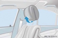
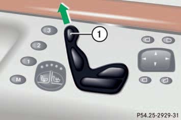
Press switch (1) upwards and hold until the head restraint is fully extended. Pull out head restraint. | |||
'''Installing front head restraints''' | |||
* Press switch (1) upwards and hold for about five seconds. | |||
* Push the head restraint down until it engages. | |||
* Adjust head restraint to desired position. | |||
==Remove/install | ==Remove/install head restraint upholstery (up to 31/08/2002)== | ||
<!-- AR91. | <!-- AR91.18-P-1830M, Remove/install head restraint upholstery, 16.9.97 | ||
MODELS 220.0 /1 up to 31.8.02 --> | |||
--> | |||
{| | {| | ||
|[[File: | |[[File:W220_Remove_install_head_restraint_upholstery_up_to_31-08-2002.jpg]] | ||
| | | | ||
* 1 - | * 1 - Upholstery | ||
* 2 - | * 2 - Expansion element | ||
* 3 - | * 3 - Housing | ||
* 4 - | * 4 - Foam insert | ||
|} | |} | ||
# Remove | # Remove head restraint and place on suitable surface | ||
# | # Completely unfold head restraint | ||
# Remove expansion element (2). Unclip expansion element (2) at first on guide rods on opposite side, then withdraw downwards. | |||
# Remove | # Remove upholstery (1) in hinge area at left and right on housing (3) | ||
# Remove upholstery (1) from clip groove on housing (3) | |||
# Slide upholstery (1) on guide rods downwards and remove | |||
# Install in the reverse order | # Install in the reverse order | ||
== | ==Remove/install headrest guide on front seat== | ||
<!-- | <!-- AR91.16-P-0050M, Remove and install headrest guide on front seat, 16.9.97 | ||
MODELS 220.0 /1 | |||
--> | |||
{| | {| | ||
|[[File: | |[[File:W220_Remove_and_install_headrest_guide_on_front_seat.jpg]] | ||
| | | | ||
* 1 - | * 1 - Headrest guide | ||
* 2 - | * 2 - Head restraint | ||
* 3 - | * 3 - Front seat backrest | ||
* | * M27m4 - Head restraint motor, raise and lower | ||
* | * M28m4 - Head restraint motor, raise and lower | ||
|} | |} | ||
# Remove | Remove: | ||
# | # Remove head restraint (2) | ||
# | # Remove tensioning element ''(seat-back lining)'' from front seat backrest | ||
# Remove head restraint raise/lower motor (M27m4/M28m4). Push motor to right first and then remove downwards. | |||
# Release catch at head restraint guide (1) using screwdriver. Push back catch (arrow) at head restraint guide (1) using screwdriver and pull head restraint (1) out upwards. | |||
# Release catch at head restraint guide (1) using pulling hook. Insert pulling hook into top of head restraint guide (1), push back catch and pull out head restraint upwards. | |||
Install: | |||
# Insert head restraint guide (1) into backrest frame of front seat backrest (3). Do not damage backrest upholstery. Catch (arrow) must point towards rear. | |||
# Engage head restraint guide (1) in backrest frame of front seat backrest (3) | |||
# Install head restraint raise/lower motor (M27m4/M28m4). Insert motor facing upwards and then push to left until it engages in backrest frame. | |||
# Fit seat-back lining to front seat backrest (3) | |||
# Install head restraint (2) | |||
= | [[File:W220_A2209700041_seat_guide.jpg|thumb|none|Head restraint guide facelift (A2209700041).]] | ||
{| class="wikitable" | |||
! Error Code | |||
! Generated By | |||
! Description | |||
|- | |||
|B1203 | |||
|ESA-FL - Electronic seat adjustment front left | |||
|Hall sensor of component M27m4 (Head restraint raise/lower motor) is faulty | |||
|} | |||
Facelift head restraint motor A2209700026 fits both sides. | |||
Note: due to normalization requirement, when installing new motor the new motor may be need to be moved manually to the position | |||
of the old motor, otherwise it may be encountered that motor is not able to move the full distance. | |||
[[File:W220_front_seat_head_restraint_motor_A2209700026.jpg|thumb|none|Facelift head restraint motor (A2209700026) removed.]] | |||
==Remove/install front seat (up to 31/08/2002)== | |||
<!-- AR91.10-P-1000M, Remove/install front seat, 15.12.09 | |||
MODEL 220.0 /1 up to 31.8.02 | |||
--> | |||
{| | {| | ||
|[[File:W220_Remove_install_front_seat_up_to_31_08_2002.jpg]] | |||
| | | | ||
* 1 - Head restraint | |||
[[File: | * 2 - Front seat | ||
* 3 - Cover | |||
* 4 - Belt end fitting | |||
* 5 - Screw | |||
* 6 - Cover | |||
* 7 - Screw | |||
|} | |||
{| | |||
|[[File:W220_Remove_install_front_seat_up_to_31_08_2002_2.jpg]] | |||
| | | | ||
* | * 8 - Pneumatic line | ||
* 9 - Retaining clamp | |||
* 10 - Seat adjustment mechanism | |||
* X55/3 - Left front seat contacting strip | |||
* X55/4 - Right front seat contacting strip | |||
|} | |} | ||
# Remove head restraint (1) | |||
# Adjust front seat (2) to front | |||
# Remove cover (3) above belt end fitting (4) | |||
# Remove bolt (5) from seat belt end fitting (4) | |||
# Remove screws (7) at the back of the seat rails | |||
# Remove covers (6) at rear of seat rails | |||
# Position front seat (2) to rear | |||
# Remove screws (7) at the front of the seat rails | |||
# Remove covers (6) at front of seat rails | |||
# Detach plug connection from pneumatic line (8) and left front seat connector block (X55/3) and right front seat connector block (X55/4) from front seat cushion. Disconnect plug connection on pneumatic line (8) with 7 mm open end wrench. | |||
# Detach retaining clamp (9) for Bowden cable seat belt height adjustment at seat adjustment mechanism (10) in direction of arrow | |||
# Lift front seat (2) and remove | |||
# Install in the reverse order | |||
Torque specification: | |||
* | * Bolt to seat runner: 50 Nm (up to 30/11/2001), 45 Nm (as of 01/12/2001) | ||
* Screw on belt end fitting: 30 Nm | |||
* | |||
<!-- | ==Remove/install front seat (as of 01/09/2002)== | ||
<!-- AR91.10-P-1000MB, Remove/install front seat, 2.12.09 | |||
MODEL 220.0 /1 as of 1.9.02 | |||
--> | |||
{| | |||
|[[File:W220_Remove_install_front_seat_as_of_01_09_2002.jpg]] | |||
| | |||
* 1 - Head restraint | |||
* 2 - Front seat | |||
* 3 - Cover | |||
* 4 - Belt end fitting | |||
* 5 - Screw (Torx 45) | |||
* 6 - Grommet | |||
* 7 - Retaining clamp | |||
* 8 - Pneumatic line plug coupling | |||
* 9 - Screw (E12 Torx) | |||
* 10 - Seat rail final cover | |||
* 11 - Cover | |||
* N32/1 - Left front seat adjustment control unit with memory | |||
* N32/2 - Right front seat adjustment control unit with memory | |||
* X28/34 - Driver seat separation point buckle emergency tensioning retractor connector (2-pin) | |||
* X28/35 - Front passenger seat separation point buckle emergency tensioning retractor connector (2-pin) | |||
|} | |||
# Switch off ignition, remove ignition key (vehicles without [[KEYLESS-GO]], code 889). | |||
# Switch off engine, remove transmitter key from vehicle (with [[KEYLESS-GO]], code 889). Keep transmitter key out of transmitter range. | |||
# Remove head restraint (1) | |||
# Adjust front seat (2) to front. Move front and rear seat cushions all the way up. Move backrest into upright position. | |||
# Remove cover (3) at rear side paneling | |||
# Remove screw/bolt (5) at belt end fitting (4). Installation: When screwing on, ensure that belt end fitting (4) remains mobile. | |||
seat | # Remove rear screws/bolts (9) from seat rails. Remove cover (11) from seat rail. | ||
seat | # Turn retaining clamp (7) at Bowden cable in direction of transmission tunnel and remove | ||
# Unhook grommet (6) with Bowden cable from bracket | |||
# Position front seat (2) to rear | |||
<!-- | # Remove front screw/bolt (9) from seat rails. Remove cover (11) from seat rail. | ||
# Pry off pneumatic line plug coupling (8) with open end wrench, size 7. Slightly incline seat toward rear in vehicle. | |||
# Detach connecting coupling (see arrow) from front seat adjustment control unit with memory, left (N32/1), right (N32/2). Slightly incline seat toward rear in vehicle. | |||
# Disconnect 2-pin driver seat connecting point buckle emergency tensioning retractor connector (X28/34), 2-pin front passenger seat connecting point buckle emergency tensioning retractor connector (X28/35). Slightly incline seat toward rear in vehicle. | |||
# Remove seat rail final cover (10) from seat rails | |||
# Lift front seat (2) and remove | |||
# Install in the reverse order | |||
# Check function of seat adjustment mechanism | |||
Torque specifications: | |||
* Bolt to seat runner: 45 Nm | |||
* Screw on belt end fitting: 30 Nm | |||
Turn retaining clamp (7) at Bowden cable in direction of transmission tunnel and remove | |||
Unhook grommet (6) with Bowden cable from bracket | |||
<!-- http://www.benzworld.org/forums/w220-s-class/2209681-help-needed-seat-removal-repair.html --> | |||
{| | |||
|[[File:W220_front_seat_retaining_clamp_removal_1.jpg|thumb|none|Retaining clamp (7) at bowden cable]] | |||
|[[File:W220_front_seat_retaining_clamp_removal_2.jpg|thumb|none|Turn retaining clamp by 90 degrees]] | |||
|[[File:W220_front_seat_retaining_clamp_removal_3.jpg|thumb|none|Grommet (6) with bowden cable]] | |||
|[[File:W220_front_seat_retaining_clamp_removal_4.jpg|thumb|none|Unhook grommet from bracket]] | |||
|} | |||
{| | {| | ||
|[[File: | |[[File:W220_SWB_left_front_seat_removed.jpg|thumb|none|Interior after left front seat removed]] | ||
| | |[[File:W220_SWB_right_front_seat_removed.jpg|thumb|none|Interior after right front seat removed]] | ||
|} | |||
==Remove/install front seat backrest (up to 31/08/2002)== | |||
<!-- AR91.10-P-1060M, Remove/install front seat backrest, 15.12.09 | |||
MODEL 220.0 /1 up to 31.8.02 | |||
* | --> | ||
* | {| | ||
* | |[[File:W220_Remove_install_front_seat_backrest_up_to_31-08-2002.jpg]] | ||
* | | | ||
* | * 1 - Trim | ||
* | * 2 - Trim | ||
* N32/1 - Left front seat adjustment control | * 3 - Seatbelt buckle | ||
* N32/2 - Right front seat adjustment control | * 4 - Screw | ||
* 5 - Screw | |||
* 6 - Backrest fitting | |||
* N32/1 - Left front seat adjustment control unit with memory | |||
* N32/2 - Right front seat adjustment control unit with memory | |||
|} | |} | ||
# Remove front seat | # Remove front seat | ||
# Remove | # Remove screw (arrow) on paneling (1) | ||
# Remove trim panel (1) | |||
# | # Remove bolt (4) and remove seat belt buckle (3) | ||
# Remove | # Remove screw (arrow) on paneling (2) | ||
# | # Remove trim panel (2) | ||
# | ## Separate pneumatic line connector for lumbar support air cushion | ||
## Remove multicontour backrest control unit from front seat (on vehicles with driver seat multicontour backrest, code 404b and passenger seat, code 405b). | |||
# Unscrew | # Disconnect backrest and head restraint adjustment connector from left front seat adjustment control unit with memory (N32/1) and right front seat adjustment control unit with memory (N32/2) | ||
# Unscrew bolt (5, 2 each) from left and right backrest fitting (6) | |||
# Remove front seat backrest from the seat adjustment mechanism | |||
# Install in the reverse order | # Install in the reverse order | ||
Torque specifications: | Torque specifications: | ||
* Bolt | * Bolt at backrest fitting: 35 Nm (up to 30/11/2001 and as of 01/12/2001) | ||
* Screw/nut on front seat belt buckle: 30 Nm | |||
==Remove/install front seat backrest (as of 01/09/2002)== | |||
<!-- AR91.10-P-1060MB, Remove/install front seat backrest, 16.12.09 | |||
MODEL 220.0 /1 as of 1.9.02 with CODE (803) model year 2003 | |||
--> | |||
{| | {| | ||
|[[File: | |[[File:W220_Remove_install_front_seat_backrest_as_of_01-09-2002.jpg]] | ||
| | | | ||
* 1 - Front seat | * 1 - Front seat backrest | ||
* 2 - Stowage compartment | * 2 - Stowage compartment | ||
* 3 - | * 3 - Left side paneling | ||
* 4 - | * 4 - Bolt | ||
* 5 - Bolt | * 5 - Bolt | ||
* 6 - | * 6 - Pneumatic line | ||
* 7 - Bolt | * 7 - Seatbelt buckle | ||
* | * 8 - Bolt | ||
* | * 9 - Cover on seat belt buckle | ||
* | * 11 - Bottom side paneling | ||
* | * 12 - Cover on the belt end fitting | ||
* N32/15 - Left front multicontour backrest control unit | |||
* N32/16 - Right front multicontour backrest control unit | |||
|} | |} | ||
{| | |||
|[[File:W220_Remove_install_front_seat_backrest_as_of_01-09-2002_2.jpg]] | |||
| | |||
* 10 - Electrical line | |||
* 13 - Backrest fitting | |||
* 14 - Bolts | |||
* N32/1 - Left front seat adjustment control unit with memory | |||
{| | |||
|[[File: | |||
| | |||
* | |||
* | |||
* | |||
* N32/1 - Left front seat adjustment control unit with memory | |||
* N32/2 - Right front seat adjustment control unit with memory | * N32/2 - Right front seat adjustment control unit with memory | ||
|} | |} | ||
# | # Remove front seat | ||
# | # Open flap on stowage compartment (2) | ||
# | ## Unclip stowage compartment (2) | ||
# Unscrew bolt ( | ## Remove fire extinguisher (for fire extinguisher code 682) | ||
# | # Remove bolts (4, 2 pieces) on the left side paneling (3) | ||
# Remove seat | # Unscrew and remove bolt (see arrow) on the belt end fitting cover (12) | ||
# Unclip | # Unscrew bolt (5) on the left side paneling (3) (see enlarged detail) | ||
# Detach left side paneling (3) in direction of travel | |||
# Remove seat | # Unclip lower side paneling (11) in the direction of the arrow (for the multicontour backrest for the driver seat code 404b and front passenger seat code 405b). | ||
# Remove multicontour backrest control unit on front seat (for the multicontour backrest for the driver seat code 404b and front passenger seat code 405b). | |||
# Remove bolt (see arrow) and bolt (8) on seat belt buckle (9) cover | |||
# Unclip retaining lug (see enlarged detail) and remove seat belt buckle (9) cover | |||
# Expose and detach electrical line (10) from the front seat backrest (1) to the front seat adjustment control unit with memory, on the left (N32/1), right (N32/2). Installation: Ensure that routing is chafing-free. | |||
# Remove bolt (14, 2 pieces) on the right and left side from the backrest fitting (13) | |||
# Remove front seat backrest (1) from seat adjustment mechanism | |||
# Install in the reverse order | # Install in the reverse order | ||
# | # Perform function test for the seatrest function | ||
Torque specifications: | |||
* Bolt on backrest fitting: 35 Nm | |||
Seat backrest leather cover is interchangeable between left and right seat. | |||
Backrest seat-back lining is interchangeable between left and right seat. | |||
Seat backrest frame has different code in EPC depending on the left or right seat, however, backrest rest has the same code and thus is interchangeable. | |||
==Remove/install front seat | {| | ||
<!-- AR91. | |[[File:W220_drivers_left_front_seat_backrest_wiring.jpg|thumb|none|Left front seat backrest wiring.]] | ||
|[[File:W220_drivers_left_front_seat_backrest.jpg|thumb|none|Left (driver's) front seat backrest removed. ]] | |||
|} | |||
==Remove/install front seat backrest cover== | |||
<!-- AR91.18-P-1820M, Remove front seat backrest cover, 16.9.97 | |||
Models 220.0 /1 --> | |||
{| | {| | ||
|[[File: | |[[File:W220_Remove_front_seat_backrest_cover_1.jpg]] | ||
| | | | ||
* 1 - | * 1 - Front seat backrest | ||
* 2 - | * 2 - Upholstery | ||
* 3 - | * 3 - Backrest frame | ||
* 4 - | * 4 - Rubberized fiber matting | ||
* | * 7 - Stitching wires | ||
|} | |} | ||
{| | |||
|[[File:W220_Remove_front_seat_backrest_cover_2.jpg]] | |||
| | |||
* 2 - Upholstery | |||
* 3 - Backrest frame | |||
* 4 - Rubberized fiber matting | |||
|} | |||
* | |||
{| | {| | ||
|[[File: | |[[File:W220_Remove_front_seat_backrest_cover_3.jpg]] | ||
| | | | ||
* 2 - Upholstery | |||
* 2 - | * 4 - Rubberized fiber matting | ||
* | * 5 - Upholstery clips | ||
* 5 - | * 6 - Upholstery clips | ||
* 6 - | |||
|} | |} | ||
Remove: | |||
# Remove head restraint guide on front seat | |||
# Remove front seat backrest (1) (up to 31/08/2002). Place front seat backrest (1) with the covering (2) downwards on a suitable base. | |||
# Remove driver's seat cushion (as of 01/09/2002). | |||
# Pull covering (2) out of the insert fold (arrows) on the bottom of the backrest frame (3) | |||
# Pull out shackle of rubberized fiber matting (4) at bottom (arrows) on backrest frame (3) | |||
# Unhook covering (2) all-round at the backrest frame (3) (arrows) | |||
# Disconnect connector for backrest ventilation (with front deluxe seat, incl. heated seat and seat ventilation, code 401a). | |||
# Remove covering (2) with rubberized fiber matting (4) from the backrest frame (3) | |||
# Remove side stapling clips (5) from the stapling wires (7) | |||
# Release stapling clips (6), to do so rotate staple clip through 90° using flat pliers | |||
# Pull the Velcro fabric strips off the rubberized fiber matting (4) | |||
# Pull covering (2) off the rubberized fiber matting (4) and remove | |||
Install: | |||
# | # Insert stapling clips (6) into rubberized fiber matting (4) and straighten out | ||
# | # Pull covering (2) at the top over the "head" of the rubberized fiber matting (4) | ||
# | # Fold upholstery (2) to side, place on rubberized fiber matting (4) and straighten out. When replacing, draw the stapling wires (7) into the fabric sleeves in the covering (2). | ||
# | # Connect longitudinal stapling wires with the stapling clips (6) | ||
# | # Align covering (2) with the rubberized fiber matting (4) and fix in position at the side with Velcro fabric strips | ||
# | # Hook side stapling clips (5) into the stapling wires (7) | ||
# | # Insert backrest frame (3) into rubberized fiber matting (4) | ||
# | # Slide shackle of rubberized fiber matting (4) (arrow) at bottom into backrest frame (3) | ||
# | # Insert covering (2) all way round on backrest frame (3) and at "header piece" | ||
# | # Install head restraint guide on the front seat | ||
# Install | # Install front seat backrest (up to 31/08/2002). | ||
# Install driver seat cushion (as of 01/09/2002). | |||
# | |||
==Remove/install front seat cushion (up to 31/08/2002)== | |||
<!-- AR91.10-P-1070M, Remove/install driver seat cushion, 15.12.09 | |||
MODEL 220.0 /1 up to 31.8.02 | |||
--> | |||
{| | {| | ||
|[[File: | |[[File:W220_Remove_install_driver_seat_cushion_up_to_31-08-2002.jpg]] | ||
| | | | ||
* 1 - | * 1 - Screw | ||
* 2 - | * 2 - Trim | ||
* 3 - | * 3 - Trim | ||
* 4 - | * 4 - Trim | ||
* 5 - | * 5 - Cap | ||
* 6 - Bolts | |||
* N32/1 - Left front seat adjustment control unit with memory | |||
* N32/2 - Right seat adjustment control unit with memory | |||
|} | |} | ||
{| | {| | ||
|[[File: | |[[File:W220_Remove_install_driver_seat_cushion_up_to_31-08-2002_2.jpg]] | ||
| | | | ||
* | * 7 - Seat adjustment mechanism | ||
* | * 8 - Seat cushion | ||
* | * 9 - Screw | ||
* | * 10 - Trim | ||
* | * 11 - Bracket | ||
* 12 - Bolts | |||
* 13 - Bolts | |||
|} | |} | ||
# Remove front seat | |||
# Remove screw (1) and remove paneling (2) | |||
# Open cap (5) and remove fire extinguisher (with fire extinguisher, code 682). | |||
# Remove screws (6, arrows) and remove paneling (4) and cap (5) | |||
# Pull off paneling (3) in direction of arrow. Ensure that retaining lugs are not damaged. | |||
# Disconnect connector from seat cushion heater on left front seat adjustment control unit with memory (N32/1) and right front seat adjustment control unit with memory (N32/2). | |||
# Remove multicontour backrest control unit from front seat (with driver seat multicontour backrest, code 404b, passenger seat, code 405b). | |||
# Remove screw (9) and remove paneling (10) | |||
# Remove screws (13) and remove seat cushion (8) forwards from the seat adjustment mechanism | |||
# Remove screws (12, arrows) from the seat cushion (8) and remove bracket (11) from the seat cushion (8) | |||
# Install in the reverse order | |||
Torque specifications: | |||
* Bolt, seat cushion to seat adjustment mechanism: 15 Nm (up to 30/11/2001 and as of 01/12/2001) | |||
==Remove/install front seat cushion (as of 01/09/2002)== | |||
<!-- AR91.10-P-1070MB, Remove/install driver seat cushion, 15.12.09 | |||
MODEL 220.0 /1 as of 1.9.02 with CODE (803) Model year 2003 | |||
--> | |||
{| | {| | ||
|[[File: | |[[File:W220_Remove_install_driver_seat_cushion_as_of_01-00-2002.jpg]] | ||
| | | | ||
* 1 - | * 1 - Seat cushion | ||
* 2 - | * 2 - Stowage compartment | ||
* | * 3 - Left side paneling | ||
* | * 4 - Screw | ||
* | * 5 - Screw | ||
* | * 11 - Bottom side paneling | ||
* 12 - Stowage compartment retaining frame | |||
* 13 - Paneling on belt end fitting | |||
* N32/15 - Left front multicontour backrest control unit | |||
* N32/16 - Right front multicontour backrest control unit | |||
* S108 - Right front multicontour backrest switch group | |||
* S109 - Left front multicontour backrest switch group | |||
|} | |} | ||
{| | |||
|[[File:W220_Remove_install_driver_seat_cushion_as_of_01-00-2002_2.jpg]] | |||
| | |||
* 1 - Seat cushion | |||
* 7 - Seat adjustment mechanism | |||
* 14 - Screw | |||
* bl - Blue connector for fan motor | |||
* N32/1 - Left front seat adjustment control unit with memory | |||
* N32/2 - Right front seat adjustment control unit with memory | |||
{| | |||
|[[File: | |||
| | |||
* 1 - | |||
* | |||
* | |||
* | |||
* | |||
|} | |} | ||
{| | # Remove front seat. Move seat cushion all the way up and to center position so that rear bolt (14) on belt buckle is accessible. | ||
|[[File: | # Open flap in stowage compartment (2) | ||
| | ## Unclip stowage compartment (2) | ||
## Remove fire extinguisher (with fire extinguisher, code 682). | |||
# Unscrew bolts (4, 2 each) from left side paneling (3) | |||
# Unscrew bolt (see arrow) at rear of paneling (13) on belt end fitting and remove | |||
# Unscrew bolt (5) from left side paneling (3) | |||
# Remove left side paneling (3) in direction of travel | |||
# Unclip bottom side paneling (11) in direction of arrow (with driver seat multicontour backrest, code 404b, passenger seat, code 405b). | |||
# Remove pneumatic lines from lumbar support control valve | |||
# Remove connector coupling from left front multicontour backrest switch group (S109), right front multicontour backrest switch group (S108) (on driver seat multicontour backrest code 404b, passenger seat code 405b or left dynamic seat including multicontour seat code 433, right code 434). | |||
# Remove omega clip (see arrow) from seat cushion frame | |||
# Remove connector coupling from dynamic seat switch (on left dynamic seat incl. multicontour seat code 433, right code 434). | |||
# Remove multicontour backrest control unit from front seat (with driver seat multicontour backrest, code 404b, passenger seat, code 405b). | |||
# Unscrew stowage compartment retaining frame (12) from cushion frame | |||
# Unscrew bolt (14, 2 each) and slide seat cushion (1) on seat adjustment mechanism (7) toward front. Do not yet remove seat cushion (1) from seat adjustment mechanism. | |||
# Disconnect blue connector on fan motor (bl) (for code (401a) front comfort seat, incl. seat heating and seat ventilation). | |||
# Remove coupling for seat cushion heater (see arrow in magnifying glass) from left front seat adjustment control unit with memory (N32/1), right front seat adjustment control unit with memory (N32/2) (for front comfort seats, incl. seat heating and seat ventilation vehicles, code 401a or right and left front seat heaters or code 873). | |||
# Remove seat cushion (1) from seat adjustment mechanism (7) | |||
# Install in the reverse order | |||
# Check seat adjustment for proper function | |||
Torque specifications: | |||
* Bolt, seat cushion to seat adjustment mechanism: 15 Nm | |||
Seat cushion frame is interchangeable between left and right seat cushion. | |||
The cushion rest and cushion leather cover, however, have different part numbers in EPC depending on the side. | |||
Passenger seat cushion has passenger occupancy sensor installed with extra connector (yellow). | |||
{| | |||
|[[File:W220_front_seat_cushion_drivers_side_bottom.jpg|thumb|none|Left (driver's) front seat cushion]] | |||
|[[File:W220_front_seat_cushion_bottom_driver_and_passenger_side.jpg|thumb|none|Front seat cushion: left and right]] | |||
|} | |} | ||
{| | {| | ||
|[[File: | |[[File:W220_front_drivers_seat_cushion_wires_heater_ventilation.jpg|thumb|none|Driver's seat cushion connectors: heating and ventilation]] | ||
| | |[[File:W220_front_passenger_seat_cushion_wires_heater_ventilation_occupancy_sensor.jpg|thumb|none|Passwnger seat cushion connectors: heating, ventilation and passenger occupancy sensor]] | ||
|} | |} | ||
Remove | ==Remove/install front seat cushion covering (up to 31/08/2002)== | ||
<!-- AR91.18-P-1800M, Remove/install front seat cushion covering, 16.9.97 | |||
MODELS 220.0 /1 up to 31.8.02 --> | |||
{| | |||
|[[File:W220_Remove_install_front_seat_cushion_covering_up_to_31-08-2002_1.jpg]] | |||
| | |||
* 1 - Upholstery | |||
* 2 - Cushion frame | |||
* 3 - Rubberized fiber matting | |||
* 4 - Upholstery clip | |||
* 5 - Staple wire | |||
|} | |||
{| | |||
|[[File:W220_Remove_install_front_seat_cushion_covering_up_to_31-08-2002_2.jpg]] | |||
{| | |||
|[[File: | |||
| | | | ||
* 1 - Upholstery | * 1 - Upholstery | ||
* 2 - | * 2 - Cushion frame | ||
* 3 - | * 3 - Rubberized fiber matting | ||
* | * 6 - Stitching wires | ||
* 7 - Upholstery clip | |||
* 8 - Foam wedge | |||
|} | |} | ||
# Remove | Remove: | ||
# | # Remove driver's seat cushion. Place driver's seat cushion on suitable surface with upholstery (1) facing downwards. | ||
# Remove | # Unclip upholstery all way round (1) from clip groove (arrows) in cushion frame (2). Relieve strain on upholstery (1) by pushing down the cushion frame. | ||
# Remove upholstery (1) in | # Remove cushion frame (2) from the rubberized fiber matting (3) | ||
# | # Remove side upholstery clips (4) from stitching wires (5). Pull upholstery (1) over outer edge of rubberized fiber matting (3). | ||
# | # Remove upholstery clips (7, 8 pcs.) from stitching wires (6). Do this by rotating upholstery clips (7) 90° using flat nose pliers. | ||
# Install | # Remove upholstery (1) from rubberized fiber matting (3). | ||
# Pull stitching wires (5, 6) from upholstery (1). Only when replacing upholstery (1). | |||
Intall: | |||
# Slide stitching wires (5) and (6) into material sleeves on upholstery (1) and straighten out. Only when fitting new upholstery (1). | |||
# Press in upholstery clips (7, 8 pcs.) into rear of rubberized fiber matting (3) and straighten out | |||
# Fold upholstery (1) to side, place on rubberized fiber matting (3) and straighten out | |||
# Use press-in tool to insert stitching wires (6) into upholstery clips (7) Installation tool for stitching wire | |||
# Insert lateral stapling clips (4) into stitching wires (5). Pull upholstery (1) over outer edge of rubberized fiber matting (3) at side and front. | |||
# Insert cushion frame (2) into rubberized fiber matting (3). With foam rubber wedges (8, 4 pcs.) inserted into cushion frame (2). | |||
# Insert upholstery (1) all way round into clip groove. Relieve strain on upholstery (1) by pushing down the cushion frame. Note retaining clamps. | |||
# Install driver's seat cushion | |||
==Remove/install | ==Remove/install front seat cushion covering (as of 01/09/2002)== | ||
<!-- AR91. | <!-- AR91.18-P-1800MB, Remove/install front seat cushion covering, 30.10.02 | ||
MODELS 220.0 /1 with CODE ( | MODELS 220.0 /1 as of 1.9.02 with CODE (803) Model year 2003 --> | ||
--> | |||
{| | {| | ||
|[[File: | |[[File:W220_Remove_install_front_seat_cushion_covering_as_of_01-09-2002.jpg]] | ||
| | | | ||
* 1 - | * 1 - Upholstery | ||
* 2 - | * 2 - Cushion frame | ||
* 3 - | * 3 - Foam padding | ||
* 4 - | * 4 - Stapling clip | ||
* 5 - | * 5 - Stitching wire | ||
|} | |} | ||
# Remove | # Remove driver's seat cushion. Place driver's seat cushion on suitable surface with upholstery (1) facing downwards. | ||
# | # Unhook covering (1) from clip groove around cushion frame (2). Relieve seat cushion cover (1) tension by pressing cushion frame (2) down. | ||
# | # Remove cushion frame (2) from foam rubber padding (3) | ||
# | # Unhook three stapling clips (see arrows) from foam rubber padding (3) at each side. Pull upholstery (1) over outer edge of foam rubber padding (3). | ||
# Remove stapling clips (4, 11 pcs.) from stitching wires (5). Do this by rotating stapling clips (4) 90° using flat nose pliers. Installation: Use push-in tool. | |||
# Remove upholstery (1) from foam rubber padding (3). Installation: Align upholstery (1) on foam rubber padding (3). | |||
# Pull stitching wire (5) out of material sleeves on upholstery (1). Only when replacing upholstery (1). | |||
# Install in the reverse order | # Install in the reverse order | ||
==Remove/install front seat | ==Remove/install front seat multicontour backrest control module (code 404b/405b)== | ||
<!-- AR91. | <!-- AR91.25-P-1750M, Remove/install front seat multicontour backrest control module, 1.10.02 | ||
MODELS 220.0 /1 | MODELS 220.0 /1 | ||
with CODE (404b) Multicontour backrest driver seat | |||
with CODE (405b) Multicontour backrest passenger seat | |||
--> | --> | ||
{| | {| | ||
|[[File: | |[[File:W220_remove_install_front_seat_multicontour_backrest_control_module.jpg]] | ||
| | | | ||
* 1 - | * 1 - Pneumatic line connecting rail | ||
* 2 - | * 2 - Bolt | ||
* 3 - | * 3 - Frame | ||
* | * 4 - Overpressure reservoir | ||
* | * 5 - Catch | ||
* 6 - Control module connecting cable | |||
* 7 - Switch group connecting cable | |||
* N32/15 - Left front multicontour backrest control module | |||
* N32/16 - Right front multicontour backrest control module | |||
* sw - Black pneumatic line with diam. of 4 mm | |||
|} | |} | ||
# Remove | # Remove front seat | ||
# Remove | # Unscrew screw (2) and remove frame (3) | ||
# Remove multicontour backrest, front left (N32/15) or right (N32/16) | |||
# Expose control module connecting cable (6) and disconnect from front seat adjustment control module (see arrow) | |||
# Expose switch group connecting cable (7) and disconnect from multicontour backrest switch group | |||
# Open catch (5) and remove pneumatic line connecting rail (1). Open catch (5) using small screwdriver (see arrow). | |||
# Unclip black pneumatic line with diam. of 4 mm (sw) to overpressure reservoir (4) (only if seat cushion or backrest has to be removed). | |||
# Install in the reverse order | # Install in the reverse order | ||
# | # Check multicontour seat backrest for proper function | ||
== | ==Remove/install front seat control module (up to 30/06/2001)== | ||
<!-- AR91. | <!-- AR91.29-P-1550M, Remove/install front seat control module, 15.1.98 | ||
MODEL 220.0 /1 up to 30.6.01 | |||
--> | --> | ||
{| | {| | ||
|[[File: | |[[File:W220_remove_install_front_seat_control_module_up_to_30_06_2001.jpg]] | ||
| | | | ||
* 1 - Front seat | * 1 - Front seat | ||
* 2 - | * 2 - Internal Torx bolt | ||
* 3 - | * 3 - Plug connections | ||
* | * 4 - Seat adjustment mechanism | ||
* | * N32/1 - Left front seat adjustment control module with memory | ||
* N32/2 - Right front seat adjustment control module with memory | |||
|} | |} | ||
# Remove | # Remove front seat (1) | ||
# Remove | # Disconnect all electrical connectors (3) | ||
# Unscrew internal Torx bolts (2) | |||
# Remove left front seat adjustment control module with memory (N32/1), right (N32/2) from bracket in seat adjuster (4) | |||
# Install in the reverse order | # Install in the reverse order | ||
# Perform | # Perform function check on electric seat adjustment | ||
==Remove/install front seat | ==Remove/install front seat control module (as of 01/07/2001)== | ||
<!-- AR91. | <!-- AR91.29-P-1550MA, Removing and installing front seat control module, 29.11.02 | ||
MODELS 220.0 /1 as of 1. | MODELS 220.0 /1 as of 1.7.01 with CODE (802) Model year 2002 --> | ||
with CODE ( | |||
--> | |||
{| | {| | ||
|[[File: | |[[File:W220_remove_install_front_seat_control_module_as_of_01_07_2001.jpg]] | ||
| | | | ||
* 1 - | * 1 - Bolt | ||
* 2 - | * 2 - Bolt | ||
* | * 3 - Control module bracket | ||
* | * 4 - Flexible shaft | ||
* 5 - Transverse rod | |||
* 6 - Pneumatic line | |||
* M27m1 - Forward and back motor | |||
* M27m2 - Rear up/down motor | |||
* M28m1 - Forward and back motor | |||
* M28m2 - Rear up/down motor | |||
* N32/1 - Left front seat adjustment control module with memory | |||
* N32/2 - Right front seat adjustment control module with memory | |||
|} | |} | ||
# | # Remove front seat | ||
# | # Remove all connectors to front and rear side of left (N32/1) and right (N32/2) front seat adjustment control module with memory | ||
# Detach | # Slacken tie straps (see arrow) at control module bracket lug (3). Installation: Use new tie straps. | ||
# Unscrew bolt (1, 2 pcs.) at front of left (N32/1) and right (N32/2) front seat adjustment control module with memory | |||
# Unscrew bolt (2, see magnification) from rear up/down motor (M27m2, M28m2) | |||
# Detach flexible shaft (4) from forward/back motor (M27m1, M28m1) | |||
# Carefully release front control module bracket (3) from transverse rod (5), (see arrow) until both plastic retaining clamps on underside of control module bracket (3) have been unclipped. Control module bracket (3) is fixed to the seat frame with a rivet (see magnification). | |||
# Unclip pneumatic line (6) at front left (N32/1) and right (N32/2) side of left front seat adjustment control module with memory | |||
# Unclip left (N32/1) and right (N32/2) front seat adjustment control module with memory from control module bracket (3) latching lug (see arrow) at front right side | |||
# Push left (N32/1) and right (N32/2) front seat adjustment control module with memory from control module bracket (3) | |||
# Install in the reverse order | # Install in the reverse order | ||
# Perform function test | # Perform front seat adjustment function test | ||
[[File:W220_drivers_left_front_seat_control_module.jpg|thumb|none|Left front seat control module (A2208205585)]] | |||
==Remove/install front seat adjustment mechanism== | |||
<!-- AR91.10-P-1450M, Remove/install front seat adjustment mechanism, 16.9.97 | |||
Models 220.0 /1 --> | |||
{| | {| | ||
|[[File: | |[[File:W220_Remove_install_front_seat_adjustment_mechanism.jpg]] | ||
| | | | ||
* 1 - | * 1 - Front seat backrest | ||
* 2 - | * 2 - Driver seat cushion | ||
* 3 - Seat adjustment mechanism | |||
* | |||
|} | |} | ||
# | # Remove front seat backrest (1) | ||
# | # Remove driver's seat cushion (2) | ||
# Remove front seat control module | |||
## Remove front seat adjustment motor group (seat cushion) - up to 30/06/2001. | |||
## Remove front seat adjustment motor group (seat cushion) (only for front and rear seat cushion and front seat forward and backward) - as of 01.07.2001. | |||
## Remove front seat adjustment motor group (seat cushion) (only for seat cushion forward and backward) - as of 01/07/2001 and up to 31/08/2002, as of 01/09/2002. | |||
# Install in the reverse order | # Install in the reverse order | ||
{| | {| | ||
|[[File: | |[[File:W220_front_seat_adjustment_mechanisms_left_right.jpg|thumb|none|Front seat adjustment mechanisms: left and right]] | ||
|[[File:W220_drivers_left_front_seat_adjustment_mechanism.jpg|thumb|none|Front left seat adjustment mechanism ([[facelift]])]] | |||
|} | |||
==Remove/install front seat adjusting motors (up to 30/06/2001)== | |||
<!-- AR91.29-P-1420M, Remove/install front seat (seat cushion) adjusting motors, 16.1.98 | |||
MODELS 220.0 /1 up to 30.6.01 --> | |||
{| | |||
|[[File:W220_Remove_install_front_seat_adjusting_motors_up_to_31-06-2001_1.jpg]] | |||
| | | | ||
* 5 - | * 1 - Front seat | ||
* 6 - | * 2 - Panel | ||
* 7 - | * 3 - Panel | ||
* | * 5 - Bracket | ||
* | * 6 - Bolts | ||
* | * 7 - Strut | ||
* M27m1 - Forward and back motor | |||
* M27m2 - Rear up/down motor | |||
* M27m3 - Front up/down motor | |||
* M27m6 - Seat cushion fore/aft motor | |||
* M28m1 - Forward and back motor | |||
* M28m2 - Rear up/down motor | |||
* M28m3 - Front up/down motor | |||
* M28m6 - Seat cushion fore/aft motor | |||
* N32/1 - Left front seat adjustment control unit with memory | |||
* N32/2 - Right front seat adjustment control unit with memory | |||
|} | |||
with | |||
{| | {| | ||
|[[File: | |[[File:W220_Remove_install_front_seat_adjusting_motors_up_to_31-06-2001_2.jpg]] | ||
| | | | ||
* | * 4 - Screw | ||
* 5 - | * 5 - Bracket | ||
* | * M27m1 - Forward and back motor | ||
* | * M27m2 - Rear up/down motor | ||
* | * M27m3 - Front up/down motor | ||
* | * M28m1 - Forward and back motor | ||
* M28m2 - Rear up/down motor | |||
* M28m3 - Front up/down motor | |||
* N32/1 - Left front seat adjustment control unit with memory | |||
* N32/2 - Right front seat adjustment control unit with memory | |||
|} | |} | ||
# Remove | # Remove front seat (1) | ||
# Remove | # Undo screws (arrows) on side paneling (2) | ||
# | # Remove side paneling (2) and (3) from front seat (1) | ||
# | # Undo bolts (6) on seat cushion fore/aft motor (M27m6) and (M28m6) and remove motor | ||
# | # Remove left front seat adjustment control unit with memory (N32/1), right front seat adjustment control unit with memory (N32/2) | ||
# | # Undo bolt (4) from the bracket (5) for the left front seat adjustment control unit with memory (N32/1), right front seat adjustment control unit with memory (N32/2) | ||
# | # Remove fore/aft motor (M27m1) and (M28m1). Remove screws (6). | ||
# | # Remove rear up/down motor (M27m2) and (M28m2). Remove screws (6). | ||
# Remove front up/down motor (M27m3) and (M28m3). Remove screws (6). | |||
# Exchange coupling assignment on seat adjustment of fore/aft motors (M27m1) and (M28m1) (only for models 220.0/1 up to chassis end number 189590, when installing new fore/aft motors (M27m1) and (M28m1)). | |||
# Undo bracket (5) for left front seat adjustment control unit with memory (N32/1), right front seat adjustment control unit with memory (N32/2) and the strut (7) of the motor group | |||
# Install in the reverse order | # Install in the reverse order | ||
# | # Check seat adjustment for proper function | ||
Torque specifications: | |||
* Bolt of seat adjustment motor: 4 Nm | |||
* | |||
===Exchange coupling assignment on seat adjustment=== | |||
<!--AR91.29-P-1420-03M, Exchange coupling assignment on seat adjustment--> | |||
== | [[File:W220_Exchange_coupling_assignment_on_seat_adjustment.jpg]] | ||
<!-- AR91. | [[File:W220_Exchange_coupling_assignment_on_seat_adjustment_2.jpg]] | ||
MODELS 220.0 /1 | [[File:W220_Exchange_coupling_assignment_on_seat_adjustment_A220589019950_with_A220589019961.jpg]] | ||
# Detach coupling (arrow) on connector assignment. | |||
# Using a suitable tool, slide contact retainer (1) in direction of arrow out of locked position. | |||
# Insert unlocking tool into coupling of contact cavity 5 and remove female contact from coupling by pulling lightly on cable. | |||
# Insert unlocking tool into coupling of contact cavity 6 and remove female contact from coupling by pulling lightly on cable. | |||
# Exchange the female contact from contact cavity 6 with the female contact from contact cavity 5. | |||
# During installation pull lightly on the cables in contact cavities 5 and 6 to check that the female contacts have engaged properly into the housing. | |||
==Remove/install front seat (frame forward/back, cushion forward/back, up/down) adjusting motors (as of 01/07/2001)== | |||
<!-- AR91.29-P-1420MA, Remove/install front seat (seat cushion) adjusting motors, 16.1.98 | |||
MODELS 220.0 /1 as of 1.7.01 seat frame forward/back, seat cushion forward/back, up/down --> | |||
{| | {| | ||
|[[File: | |[[File:W220_Remove_install_front_seat_adjusting_motors_as_of_01-07-2001.jpg]] | ||
| | | | ||
* 5 - | * 1 - Motor | ||
* 6 - | * 2 - Flexible shaft | ||
* 3 - Bolt | |||
* 4 - Bolt | |||
* 5 - Seat adjustment shaft | |||
* 6 - Wiring connector | |||
* M27 - Left front seat adjustment motor group with memory | |||
* M27m1 - Forward and back motor | |||
* M27m2 - Rear up/down motor | |||
* M27m3 - Front up/down motor | |||
* M28 - Right front seat adjustment motor group with memory | |||
* M28m1 - Forward and back motor | |||
* M28m2 - Rear up/down motor | |||
* M28m3 - Front up/down motor | |||
|} | |} | ||
# Remove front seat | # Remove front seat (1) | ||
# | # Unscrew screw (3, 2 pcs.) from front up/down motor (M27m3, M28m3). Only when replacing front up/down motor (M27m3, M28m3). | ||
# Lift front up/down motor (M27m3, M28m3) slightly from transmission, kink over flexible shaft (2) and remove. Only when replacing front up/down motor (M27m3, M28m3). | |||
# | # Detach seat adjustment shaft (5) from forward/back motor (M27m1, M28m1). Only when replacing forward/back motor (M27m1/M28m1). | ||
# | # Unscrew screws (3, 2 pcs.) from forward/back motor (M27m1, M28m1). Only when replacing forward/back motor (M27m1/M28m1). | ||
# | # Detach forward/back motor (M27m1, M28m1) from transmission. Only when replacing forward/back motor (M27m1/M28m1). Flexible shaft (2) remains in transmission. | ||
# | # Unscrew screw (4) from control module bracket. Only when replacing rear up/down motor (M27m3, M28m3). | ||
# | # Unscrew screw (3, 2 pcs.) from rear up/down motor (M27m2, M28m2). Only when replacing rear up/down motor (M27m3, M28m3). | ||
# Remove rear raise/lower motor (M27m2/M28m2) from transmission. Only when replacing rear up/down motor (M27m3, M28m3). | |||
# Detach electrical plug (6) from motor (1). Installation: Slide flexible shaft (2) into motor (1) as far as it will go. | |||
# Install in the reverse order | # Install in the reverse order | ||
# Perform | # Perform function check of respective electric seat adjuster | ||
Torque specification: | |||
* Bolt of seat adjustment motor: 4 Nm | |||
==Remove/install front seat (seat cushion forward/back) adjusting motors (as of 01/07/2001 up to 31/08/2002)== | |||
<!-- AR91.29-P-1420MB, Remove/install front seat (seat cushion) adjusting motors, 16.1.98 | |||
MODEL 220.0 /1 as of 1.7.01 up to 31.8.02 Seat cushion forward/back --> | |||
{| | {| | ||
|[[File: | |[[File:W220_Remove_install_front_seat_adjusting_motors_as_of_01-07-2001_up_to_31-08-2002.jpg]] | ||
| | | | ||
* 1 - | * 1 - Bolt | ||
* 2 - | * 2 - Side paneling | ||
* 3 - | * 3 - Cover | ||
* 4 - Belt end fitting | |||
* 5 - Bolt | |||
* 6 - Bolt | |||
* 7 - Transmission | |||
* M27m6 - Seat cushion forward/back motor | |||
* M28m6 - Seat cushion forward/back motor | |||
- | |||
* | |||
* | |||
* | |||
* N32/1 - Left front seat adjustment control unit with memory | * N32/1 - Left front seat adjustment control unit with memory | ||
* N32/2 - Right front seat adjustment control unit with memory | * N32/2 - Right front seat adjustment control unit with memory | ||
* | * vi - Violet coupling | ||
|} | |} | ||
# | # Move front seats toward front. Move front and back seat cushions up as far as possible. | ||
# | # Remove cover (3) from side trim (2) | ||
# | # Unscrew screw (5) from belt end fitting (4). Installation: When screwing on, please ensure that the belt end fitting (4) remains mobile. | ||
# Unscrew | # Unscrew bolt (1) and unclip and remove upper trim (2) | ||
# | # Unscrew screws (6, 2 screws) from seat cushion forward/back motor (M27m6, M28m6) | ||
# Remove seat | # Remove seat cushion forward/back motor (M27m6, M28m6) from transmission (7). Shaft remains in transmission (7). Installation: Motor must be inserted into pilot stud (arrows). | ||
# Unclip connecting cable to underside of left (N32/1) and right (N32/2) front seat adjustment control unit with memory. Installation: Carefully clip connecting cable into retaining clamps on underside of control unit. | |||
# Unplug violet coupling (vi) from left (N32/1) and right (N32/2) front seat adjustment control unit with memory | |||
# Remove seat cushion forward/back motor (M27m6, M28m6) with connecting cable | |||
# Install in the reverse order | |||
# Check seat adjustment for proper function | |||
Torque | Torque specification: | ||
* Bolt of seat adjustment motor: 4 Nm | |||
* Screw/nut on front seat belt buckle: 30 Nm | * Screw/nut on front seat belt buckle: 30 Nm | ||
==Remove/install front seat | ==Remove/install front seat (seat cushion forward/back) adjusting motors (as of 01/09/2002)== | ||
<!-- AR91. | <!-- AR91.29-P-1420MC, Remove/install front seat (seat cushion) adjusting motors, 16.1.98 | ||
MODEL 220.0 /1 as of 1.9.02 with CODE (803) Model year 2003 seat cushion forward/back --> | |||
{| | {| | ||
|[[File: | |[[File:W220_Remove_install_front_seat_adjusting_motors_as_of_01-09-2002.jpg]] | ||
| | | | ||
* 1 - | * 1 - Front seat | ||
* 2 - Bolt | * 2 - Stowage compartment | ||
* | * 3 - Cover | ||
* | * 4 - Belt end fitting | ||
* | * 5 - Bolt | ||
* 6 - Bolt | |||
* 7 - Bolt | |||
* 12 - Left side paneling | |||
* 13 - Rear side trim | |||
* M27m6 - Seat cushion forward/back motor | |||
* M28m6 - Seat cushion forward/back motor | |||
|} | |} | ||
# | # Adjust front seat (1) to front. Move front and back seat cushions up as far as possible. | ||
# | # Remove cover (3) from rear side trim (13) | ||
# Remove | # Unscrew screw (5) from belt end fitting (4). Installation: When screwing on, please ensure that the belt end fitting (4) remains mobile. | ||
# Unscrew | # Remove screw (see arrow) from rear side trim (13) | ||
# Unscrew screw (6, see magnification) from left side trim (12) | |||
# Open stowage compartment flap (2) | |||
## Unclip and remove stowage compartment (2) | |||
## Remove fire extinguisher (for vehicles with fire extinguisher code 682) | |||
# Unscrew screws (6, 2 screws) from left side trim (12) | |||
# Pull off left side trim (12) in direction of travel | |||
# Unscrew screw (7, 2 screws) from seat cushion forward/back motor (M27m6, M28m6) | |||
# Remove seat cushion forward/back motor (M27m6, M28m6) from transmission. Shaft remains in transmission. | |||
# Unplug connector from seat cushion forward/back motor (M27m6, M28m6) | |||
# Install in the reverse order | # Install in the reverse order | ||
# Perform function check of seat cushion forward/back facility | |||
Torque | Torque specification: | ||
* Bolt of seat adjustment motor: 4 Nm | |||
* Screw/nut on front seat belt buckle: 30 Nm | * Screw/nut on front seat belt buckle: 30 Nm | ||
==Remove/install seat | ==Remove/install front seat (backrest and head restraint) adjusting motors== | ||
<!-- AR91. | <!-- AR91.29-P-1430M, Remove/install front seat (seat backrest) adjusting motors, 19.1.98 | ||
Remove/install seat | MODELS 220.0 /1 | ||
backrest adjustment and head restraint adjustment | |||
--> | --> | ||
{| | {| | ||
|[[File: | |[[File:W220_Remove_install_front_seat_backrest_and_head_restraint_adjusting_motors.jpg]] | ||
| | | | ||
* 1 - | * 1 - Upholstery | ||
* 2 - | * 2 - Head restraint wiring harness | ||
* | * 3 - Bolt | ||
* 7 - Seat belt buckle | |||
* 8 - Bolt | |||
* 9 - Side paneling | |||
* 10 - Wiring harness | |||
* M27m4 - Head restraint motor, up and down | |||
* M27m5 - Backrest forward/back motor | |||
* M28m4 - Head restraint up/down motor | |||
* M28m5 - Backrest forward/back motor | |||
* N32/1 - Left front seat adjustment control module with memory | |||
* N32/2 - Right front seat adjustment control module with memory | |||
|} | |} | ||
# Remove | |||
# | # Remove front seat | ||
# | # Remove seat-back lining from seat backrest | ||
# Remove head restraint up/down motor (M27m4/M28m4). Only when replacing. First press head restraint up/down motor (M27m4/M28m4) to right side and then remove downward. | |||
# | # Expose upholstery (1) around backrest forward/back motor (M27m5, M28m5) (see arrow) | ||
# Remove side paneling (9) from seat belt buckle (7). Screws (8, arrow) and retaining clip (see detail). | |||
# Disconnect head restraint wiring harness (2) from head restraint up/down motor (M27m4, M28m4). Head restraint wiring harness (2) and wiring harness (10) are connected together with the backrest forward/back motor (M27m5, M28m5). | |||
# Expose head restraint wiring harness (2) at right side of backrest frame | |||
# Expose wiring harness (1) of left (N32/1), right (N32/2) front seat adjustment control module with memory as far as backrest forward/back motor (M27m5, M28m5). Installation: Fix wiring harness (10) to existing cables using tie straps. | |||
# Unscrew screw (3) from right backrest frame and pull backrest forward/back motor (M27m5, M28m5) out towards rear | |||
# Install in the reverse order | # Install in the reverse order | ||
# | # Check seat adjustment for proper function | ||
Torque specifications: | |||
* Bolt, backrest adjustment motor: 5 Nm | |||
==Remove/install seat | ==Remove/install front seat blower regulator for seat ventilation motors (code 401)== | ||
<!-- AR91. | <!-- AR91.30-P-1910M, Remove/install blower regulator for seat ventilation motors in front seat, 16.6.98 | ||
MODELS 220.0 /1 with CODE (401a) Front luxury seat, incl. heated seat and seat ventilation | |||
--> | --> | ||
{| | {| | ||
|[[File: | |[[File:W220_Remove_install_blower_regulator_for_seat_ventilation_motors_in_front_seat.jpg]] | ||
| | | | ||
* 1 - | * 1 - Front seat backrest | ||
* | * 2 - Backrest frame | ||
* | * 3 - Backrest cover | ||
* | * 4 - Bolt | ||
|} | * 5 - Connector | ||
* N29/5 - Left front seat ventilation blower regulator | |||
* N29/6 - Right front seat ventilation blower regulator | |||
|} | |||
# Remove | # Remove tensioning element (''front seat backrest seat-back lining'') from front seat backrest (1) | ||
# | # Detach backrest upholstery (3) from backrest frame (2) | ||
# Disconnect connector (5) from left (N29/5) and right (N29/6) front seat ventilators | |||
# | # Unscrew bolt (4) and remove left (N29/5) and right (N29/6) front seat ventilator blower regulator | ||
# Install in the reverse order | # Install in the reverse order | ||
# | # Perform seat ventilation function test | ||
==Remove/install front seat cushion ventilation motors (code 401)== | |||
<!-- AR91.30-P-1950M, Remove/install front seat cushion ventilation motors, 20.2.98 | |||
MODELS 220.0 /1, 215 with CODE (401a) Front luxury seat, incl. heated seat and seat ventilation | |||
--> | |||
{| | |||
|[[File:W220_Remove_install_front_seat_cushion_ventilation_motors.jpg]] | |||
| | |||
* 1 - Driver seat cushion | |||
* 2 - Seat cushion cover | |||
* 3 - Rubberized matting/foamed material surface | |||
* M18/9 - Left front seat cushion ventilation motor group | |||
* M18/11 - Right front seat cushion ventilation motor group | |||
|} | |||
== | # Remove driver's seat cushion (1) | ||
* | # Remove cover of front seat cushion | ||
# Remove defective front left (M18/9) and right (M18/11) seat cushion ventilation motor group together with rubberized fiber matting/foam rubber (3). Individual motors are not replaced - the entire motor group with rubberized fiber matting/foam rubber (3) is replaced. | |||
# Install in the reverse order | |||
# Perform seat ventilation function check | |||
==Remove/install front seat backrest ventilation motors== | |||
<!-- AR91.30-P-1900M, Removing and installing the seat ventilation motors on the front seat backrest, 12.6.98 | |||
MODELS 220.0 /1, 215 with CODE (401a) Front luxury seat, incl. heated seat and seat ventilation | |||
--> | |||
{| | |||
|[[File:W220_Removing_and_installing_the_seat_ventilation_motors_on_the_front_seat_backrest.jpg]] | |||
| | |||
* 1 - Front seat backrest | |||
* 2 - Backrest cover | |||
* 3 - Rubberized fiber matting | |||
* M18/10 - Left front seat backrest ventilation motor group | |||
* M18/12 - Right front seat backrest ventilation motor group | |||
|} | |||
# Remove covering on front seat backrest | |||
# Remove defective front left (M18/10) and right (M18/12) seat backrest ventilation motor group together with rubberized fiber matting (3). Individual motors are not replaced - the entire motor group with rubberized fiber matting (3) is replaced. | |||
# Install in the reverse order | |||
# Perform seat ventilation function check | |||
==Remove/install front seat multicontour backrest control switch (code 404/405) (up to 31/08/2002)== | |||
<!-- AR91.25-P-1760M, Remove/install front seat multicontour backrest control switch, 25.2.98 | |||
MODELS 220.0 /1 up to 31.8.02, | |||
215 | |||
with CODE (404b) Multicontour backrest driver seat | |||
with CODE (405b) Multicontour backrest passenger seat --> | |||
{| | |||
|[[File:W220_Remove_install_front_seat_multicontour_backrest_control_switch_up_to_31-08-2002.jpg]] | |||
| | |||
* 1 - Paneling | |||
* 2 - Assembly wedge | |||
* S108 - Right front multicontour backrest switch group | |||
* S109 - Left front multicontour backrest switch group | |||
|} | |||
# Unclip front right (S108), left (S109) multicontour backrest switch group out of front seat paneling (1) with assembly wedge (2) | |||
# Disconnect electrical connector | |||
# Install in the reverse order | |||
# Perform multicontour backrest function check | |||
==Remove/install front seat multicontour backrest control switch (code 404/405) (as of 01/09/2002)== | |||
<!-- AR91.25-P-1760MB, Remove/install front seat multicontour backrest control switch, 1.10.02 | |||
MODELS 220.0 /1 as of 1.9.02 | |||
with CODE (803) Model year 2003 | |||
with CODE (404b) Multicontour backrest driver seat | |||
with CODE (405b) Multicontour backrest passenger seat | |||
--> | |||
{| | |||
|[[File:W220_Remove_install_front_seat_multicontour_backrest_control_switch_as_of_01-09-2002.jpg]] | |||
| | |||
* 1 - Electrical connecting cable | |||
* 2 - Cover | |||
* S108 - Right front multicontour backrest switch group | |||
* S109 - Left front multicontour backrest switch group | |||
|} | |||
# Drive front seat backwards. Move seat cushion upwards as far as possible. | |||
# Push front right (S108), left (S109) multicontour backrest switch group out of cover (2). Move hand beneath cover (2) and push switch group out. | |||
# Detach electrical connecting cable. Omega clip may need to be removed from seat cushion frame (see arrow). | |||
# Install in the reverse order | |||
# Perform function test of front right (S108), left (S109) multicontour backrest switch group | |||
==Remove/install multicontour backrest center air cushion (code 404/405)== | |||
<!--AR91.25-P-1740M, Remove/install multi-contour backrest air cushion, 1.10.02 | |||
MODEL 220.0 /1 | |||
with CODE (404b) Multicontour backrest driver seat | |||
with CODE (405b) Multicontour backrest passenger seat | |||
center air cushion | |||
--> | |||
{| | |||
|[[File:W220_Remove_install_multi-contour_backrest_air_cushion.jpg]] | |||
| | |||
* 5 - T-piece | |||
* 6 - Center air cushion | |||
* 7 - Side air cushion | |||
* 8 - Pneumatic line | |||
* 9 - Seat frame | |||
* 10 - Reinforcement plate | |||
|} | |||
# Remove driver's seat cushion | |||
# Remove covering on front seat backrest. Only remove backrest covering with rubberized fiber matting from backrest frame | |||
# Pull off all pneumatic line from the T-piece (5, see enlarged section) on the back of the center air cushion (6) | |||
# Pull all pneumatic lines out of the tongues on the back of the center air cushion (6) | |||
# Pull strip of adhesive tape on the top part of the center air cushion (6) off the backrest frame. Installation: Fasten the upper air cushion of the center air cushion (6) with strip of adhesive tape so that they cannot fold down. | |||
# Unfold lower tongues (see arrows) of the reinforcement plate (10) downwards out of the backrest frame. Installation: Secure tongues after turning around on grid. | |||
# Press out the corners (see arrow, top) of the reinforcement plate (10) on the right and left next to the head restraint guides. Do not damage the corners of the reinforcement plate (10). Installation: The upper retainer tabs (see arrow, bottom) of the reinforcement plate (10) must be guided into the second grid brace from above. | |||
# Detach pneumatic lines (8) from seat frame (9) and re-convert up to the center air cushion (6). Ensure that it cannot chafe. Installation: Fasten the pneumatic lines (8) to the seat frame (9) with a tie strap (see arrow). | |||
# Pull center air cushion (6) upwards off the backrest frame | |||
# Install in the reverse order | |||
# Carry out function check of multicontour backrest | |||
==Remove/install multicontour backrest side air cushions (code 404/405)== | |||
<!-- AR91.25-P-1741M, Remove/install multicontour backrest side air cushions, 11.11.02 | |||
MODELS 220.0 /1 | |||
with CODE (404b) Multicontour backrest driver seat | |||
with CODE (405b) Multicontour backrest passenger seat | |||
--> | |||
{| | |||
|[[File:W220_Remove_install_multicontour_backrest_side_air_cushions.jpg]] | |||
| | |||
* 2 - Backrest frame | |||
* 5 - T-piece | |||
* 7 - Side air cushion | |||
* 10 - Bolt | |||
* 11 - Retaining strap | |||
* 12 - Bracket | |||
|} | |||
# Remove driver's seat cushion | |||
# Remove covering on front seat backrest. Only remove backrest upholstery with rubberized fiber matting from front seat backrest. | |||
# Detach pneumatic line for side air cushion (7) from T-piece (5) at rear of center air cushion (see magnifying glass) | |||
# Pull pneumatic line out of tab on rear of center air cushion | |||
# Undo both tensioning straps (11) around side air cushion (7) from backrest frame (2) | |||
# Unscrew screw (10) from backrest frame (2) | |||
# Push bracket (12) with side air cushion (7) upwards and remove | |||
# Slacken retaining straps (11) on bracket (12) | |||
# Pull side air cushion (7) from bracket (12) and remove | |||
# Install in the reverse order | |||
# Perform multicontour backrest function check | |||
==Remove/install front seat backrest frame overpressure reservoir== | |||
<!-- AR91.25-P-1550M, Removing and installing backrest frame overpressure reservoir, 28.5.98 | |||
MODELS 220.0 /1 | |||
except CODE (433) Left dynamic seat, incl. multicontour seat | |||
except CODE (434) Right dynamic seat, incl. multicontour seat | |||
--> | |||
{| | |||
|[[File:W220_Removing_and_installing_backrest_frame_overpressure_reservoir.jpg]] | |||
| | |||
* 1 - Front seat | |||
* 2 - Pneumatic connecting line | |||
* 3 - Overpressure reservoir | |||
* 4 - Cushion frame | |||
|} | |||
# Remove front seat (1) | |||
# Removing multicontour backrest control module from front seat (with driver seat multicontour backrest code 404b, passenger seat code 405b). | |||
# Detach pneumatic connecting line (2) from overpressure reservoir (3) | |||
# Push overpressure reservoir (3) from cushion frame (4) using assembly wedge. Installation: When installing the overpressure reservoir (3), ensure that the retaining clamp engages in the hole in the cushion frame. | |||
# Install in the reverse order | |||
# Perform function check of lumbar support or multicontour backrest | |||
[[File:W220_front_seat_overpressure_reservoir.jpg|thumb|none|Front seat overpressure reservoir]] | |||
==Remove/install front seat backrest lumbar support air cushion (except code 404/405/433/434)== | |||
<!-- AR91.25-P-1445M, Removing and installing lumbar support air cushion from front seat backrest, 20.1.98 | |||
MODELS 220.0 /1 | |||
except CODE (404b) Multicontour backrest driver seat | |||
except CODE (405b) Multicontour backrest passenger seat | |||
except CODE (433) Left dynamic seat, incl. multicontour seat | |||
except CODE (434) Right dynamic seat, incl. multicontour seat | |||
--> | |||
Shown on vehicle without front luxury seat, incl. heated seat and seat ventilation, code 401a: | |||
{| | |||
|[[File:W220_Removing_and_installing_lumbar_support_air_cushion_from_front_seat_backrest.jpg]] | |||
| | |||
* 1 - Front seat backrest | |||
* 2 - Backrest cover | |||
* 3 - Backrest frame | |||
* 4 - Rubberized fiber matting | |||
* 5 - Reinforcement plate | |||
* M27m4 - Head restraint motor, raise and lower | |||
* M28m4 - Head restraint motor, raise and lower | |||
|} | |||
{| | |||
|[[File:W220_lumbar_support_reinforcement_plate_and_air_cushion.jpg]] | |||
| | |||
* 5 - Reinforcement plate | |||
* 6 - Air cushion | |||
|} | |||
# Remove front seat backrest (1) | |||
# Remove tensioning element (''seat backrest seat-back lining'') from front seat backrest | |||
# Remove head restraint raise/lower motor (M27m4/M28m4). Push motor to right first and then remove downwards. | |||
# Place front seat backrest (1) onto a suitable underlay with the backrest cover (2) facing downwards | |||
# Pull backrest upholstery (2) out of clip groove (arrows) at bottom of backrest frame (3) | |||
# Pull out rubberized fiber matting (4) lug (arrows) at bottom of backrest frame (3) | |||
# Detach lugs on reinforcement plate (5) from spring wire of backrest frame (3). Do not damage lugs. | |||
# Pull reinforcement plate (5) with air cushion (6) out of backrest frame (3). Lift backrest frame (3) with spring wire from backrest upholstery (2) with rubberized fiber matting (4). | |||
# Install in the reverse order | |||
# Perform lumbar support function check | |||
==Remove/install front seat backrest lumbar support control valve== | |||
<!-- AR91.25-P-1440M, Removing and installing lumbar support control valve from front seat backrest, 21.1.98 | |||
MODELS 220.0 /1 | |||
except CODE (404b) Multicontour backrest driver seat | |||
except CODE (405b) Multicontour backrest passenger seat | |||
except CODE (433) Left dynamic seat, incl. multicontour seat | |||
except CODE (434) Right dynamic seat, incl. multicontour seat | |||
--> | |||
{| | |||
|[[File:W220_Removing_and_installing_lumbar_support_control_valve_from_front_seat_backrest.jpg]] | |||
| | |||
* 1 - Control valve | |||
* 2 - Paneling | |||
* 3 - Assembly wedge | |||
|} | |||
With model refinement 2003 (as of 01/09/2002) | |||
the position of the control valve (1) has been | |||
changed to the inboard side of the seat. | |||
# Unclip control valve (1) with assembly wedge (3) from front seat paneling (2) | |||
# Detach pneumatic line and disconnect pneumatic connector. Pay attention to line routing. | |||
# Install in the reverse order | |||
# Perform lumbar support function check | |||
==Front passenger seat occupied and child seat recognition sensor (B48)== | |||
{| | |||
|[[File:W220_Front_Seat_Occupant_Sensor_A2208211681.jpg|thumb|none|Seat occupant sensor (A2208211681)]] | |||
|[[File:W220_Front_Seat_Occupant_Sensor_module_A2208211681.jpg|thumb|none|Occupant sensor module (A2208211681)]] | |||
|} | |||
If the SRS indicator and warning lamp stays on or comes on intermittently a possible cause is that the passenger seat occupancy sensor (also known as weight sensor or SRS sensor mat) is faulty or failing. | |||
{| class="wikitable" | |||
! Error Code | |||
! Generated By | |||
! Description | |||
|- | |||
|9028 | |||
|AB - Airbag | |||
|The coding for component B48 (Front passenger seat occupied and child seat recognition) is faulty. | |||
|} | |||
There are four options to fix the SRS indicator and warning lamp staying on: | |||
# Replace the front passenger seat occupied and child seat recognition sensor (B48). The sensor costs around EUR 480 and its replacement involves dissecting seat cushion (be warned this is a substantial task). The DAS can be used to test the connection to see if the seat is empty or occupied; it should set off as occupied after 26 lbs" (12Kg). | |||
# Diagnose where the issue is occurring and fix the sensor (see below). | |||
# Disable the passenger seat occupancy sensor in DAS (see section below). | |||
# Replace the sensor with an electronic sensor emulator (see section below). | |||
=== Fixing seat occupancy sensor === | |||
If the Airbag ECU says it can't communicate with the seat occupancy sensor, or open or shorted wiring, then any one of these causes may exist: | |||
* Breakage of electrical cable between the plug connector and the sensor (quite common). If this is the case the wire can be repaired. | |||
* The sensor elements may be dead | |||
* The sensor electronics may be shorted. This can be quickly verified by measuring the voltage between the red and brown wires in the yellow connector, the voltage should be about 12V DC. The sensor mat gets the power from the seat control module located under the passenger seat. If it is around 0.6V, the sensor is short-circuiting the supply voltage to the ground which causes the built-in circuit protection to drop the voltage to 0.6V when the sensor is connected. The electronics are in the white box inside the seat cushion. The white box is filled with some caulk type filler. Nasty job, this box is neither meant to be opened nor repaired. Once opened and the caulk excavated (using knives, screw drivers and a heat gun) to reveal the components, there can be found a 15uF tantalum capacitor which is shorted when voltage is applied to it. It can be replaced with a regular electrolytic capacitor. | |||
===Disabling seat occupancy sensor in DAS=== | |||
To disable passenger seat occupancy sensor in DAS select control unit "AB - Airbag" -> "Development data" -> "Control unit adaptations" -> "Control unit adaptations (Variant coding)" -> "Fahrzeugausstattung kodieren" and change "AKSE/OC Beifahrer" from "ja" to "nein" (see photo below). | |||
[[File:W220_DAS_disable_passenger_occupancy_sensor.png|thumb|none|DAS: Passenger seat occupancy sensor enabled]] | |||
In case "AB - Airbag" control unit has been reset, the "Initial startup" will reset the module to default settings enabling the passenger seat occupancy sensor. If seat occupancy sensor will throw error codes the "Initial startup" will complete only partially showing "Initial startup could only be partially completed. Cause: - There are current fault codes present.". The "Initial startup" can be completed fully by locking the control module using "Development data" -> "Actuations" -> "Complete index of actuations" -> "Steuergerät verriegeln (FN_SG_Verriegeln)". This will lock the ECU and SRS light will go off. | |||
===Installing seat occupancy sensor emulator=== | |||
An electronic emulator may be purchased on eBay for a few dollars and substituted for the SRS Sensor Mat. Search for something like "seat occupation sensor emulator W220" (~EUR 10). | |||
There are two types of sensors available depending on W220 model year: | |||
* Type 6 for pre-[[facelift]] W220 | |||
* Type 2 for [[facelift]] W220 | |||
'''Safety note:''' The emulator simulates that there is always someone sitting in the passenger seat, so in case of an accident, the airbag goes on. | |||
Do not carry babies or children in the front seat, activating the airbag can cause serious damage in the event of a collision. | |||
The emulator is not a simple device but contains several electronic components. | |||
{| | |||
|[[File:W220 SRS Emulator 001.JPG|thumb|none|Seat occupation sensor emulator (Type 6)]] | |||
|[[File:W220 SRS Emulator 002.JPG|thumb|none|Internal view of the emulator]] | |||
|[[File:W220_seat_occupation_sensor_emulator_type_2.jpg|thumb|none|Seat occupation sensor emulator (Type 2)]] | |||
|} | |||
Install of the emulator: | |||
# Put the seat fully forward and then lift up the rear section and place on a suitable support to expose the underneath part of the seat. | |||
# Identify the SRS occupancy sensor connector. It is the yellow connector with red, white and brown wires. | |||
# Unplug the SRS occupancy sensor and make the cable accessible. You may have to cut one or two plastic ties to fully release the cable. Then cut the plug off the cable at the point marked with the red arrow. | |||
# The cut-off plug may now be taken to a workbench and the emulator soldered to the plug leads. Observe the correct colors, i.e., red to red (+12V), white to white (data) and brown to brown (Ground). Make sure to place heat shrink sleeving over the emulator wires before connecting them. | |||
# Shrink the protective sleeving and the emulator is now finished. | |||
# Reconnect the SRS occupancy sensor plug to its socket (left red arrow) and secure with plastic tie to the existing bunch of cables (right red arrow). | |||
# Reassemble the passenger seat. | |||
{| | |||
|[[File:W220 SRS Emulator 003.JPG|thumb|none|Occupancy sensor connector (shown on [[RHD]] vehicle)]] | |||
|[[File:W220 SRS Emulator 004.JPG|thumb|none|Cut the cable here]] | |||
|} | |||
{| | |||
|[[File:W220 SRS Emulator 005.JPG|thumb|none|Emulator soldered to the plug]] | |||
|[[File:W220 SRS Emulator 006.JPG|thumb|none|Emulator with the plug]] | |||
|[[File:W220 SRS Emulator 007.JPG|thumb|none|Emulator with the plug installed]] | |||
|} | |||
===Remove/install seat occupied recognition sensor (up to 31/08/2002)=== | |||
<!-- AR91.60-P-0720M, Remove/install seat occupied recognition sensor, 12.12.97 | |||
MODEL 215, 220.0 /1 up to 31.8.02 | |||
--> | |||
{| | |||
|[[File:W220_Remove_install_seat_occupied_recognition_sensor_up_to_31-08-2002.jpg]] | |||
| | |||
* 1 - Seat occupation connector | |||
* B48 - Passenger seat occupied and child seat recognition sensor | |||
* N32/1 - Left front seat adjustment control module with memory | |||
* N32/2 - Right front seat adjustment control module with memory | |||
|} | |||
# Remove cover of front seat cushion. On passenger-side only. | |||
# Switch off ignition, withdraw ignition key | |||
# Switch off engine, remove transmitter key from vehicle (with keyless go code 889). Keep transmitter key outside the transmitter range. | |||
# Guide the connector (1) upwards out of the rubberized fiber matting | |||
# Remove the front passenger seat occupied and child seat recognition sensor (B48) from the rubberized fiber matting. Installation: Lay the front passenger seat occupied and child seat recognition sensor (B48) evenly on the rubberized fiber matting. The woven side must face upwards. Do not kink front passenger seat occupied and child seat recognition sensor (B48). | |||
# Install in the reverse order | |||
# Carry out diagnosis | |||
===Remove/install seat occupied recognition sensor (as of 01/09/2002)=== | |||
<!-- AR91.60-P-0720MB | |||
Remove/install seat occupied recognition sensor, 25.11.02 | |||
MODEL 220.0 /1 as of 1.9.02 | |||
Front passenger seat only | |||
--> | |||
{| | |||
|[[File:W220_Remove_install_seat_occupied_recognition_sensor_as_of_01-09-2002.jpg]] | |||
| | |||
* 1 - Control module with connection line | |||
* 2 - Foam padding | |||
* B48 - Passenger seat occupied and child seat recognition sensor | |||
|} | |||
# Remove cover of front seat cushion. On passenger-side only. | |||
# Pull control module with connection line (1) out of the end face of the foam padding (2) (see arrow). Guide connection line through the slot in the foam padding (2). | |||
# Open foam padding (2) on the seat surface and expose front passenger seat occupied and child seat recognition sensor (B48) | |||
# Pull fastening hooks (see arrows) out of the foam padding (2). Pull out the fastening hooks slowly and carefully so that the foam support (2) is not damaged. | |||
# Pull out the control module with connection line (1) between the core and seat surface of the foam padding (2) | |||
# Remove front passenger seat occupied and child seat recognition sensor (B48) from seating surface of the foam support (2).Installation: It is essential to ensure that the film with the identification "TOP" (see enlarged section) is inserted upwards. | |||
# Install in the reverse order | |||
# Carry out diagnosis | |||
==Retrofit front seat height adapter== | |||
<!-- AN91.10-P-0002M, Retrofit front seat height adapter, 10.1.08 | |||
MODEL 220 --> | |||
{| | |||
|[[File:W220_retrofit_front_seat_height_adapter.jpg]] | |||
| | |||
* 1 - Spacer | |||
* 2 - Foam rubber | |||
* 3 - Covers | |||
* 4 - Bolts | |||
* 5 - Front seat | |||
|} | |||
# Remove bolts (4, 4 pieces) on the front and rear seat rail | |||
# Raise front seat frame, place spacers (1) (part number A2209101736) on the right and left as well as at the front and rear under the under the seat rails and fasten with the bolts contained in the accessories. Do not damage covers (3). | |||
# Clamp foamed material (2) in each case in front of and behind the spacer (1) under the covers (3) of the seat rails | |||
# Check seat adjustment for proper function | |||
# If the package changes, supplement the code or designation of the relevant special equipment on the vehicle data card | |||
Torque specifications: | |||
* Bolt to seat runner: 50 Nm (up to 30/11/2001) | |||
Latest revision as of 17:15, 20 December 2025
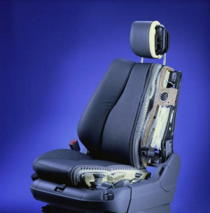
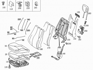 |
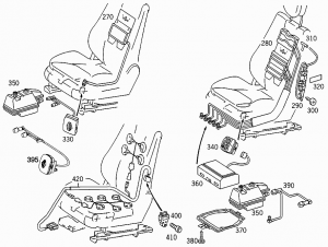 |
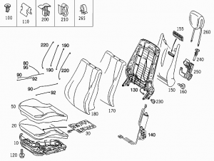 |
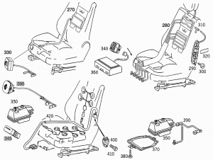 |
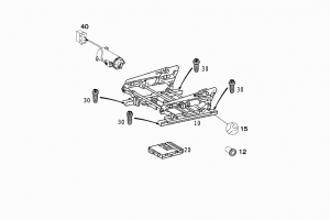 |
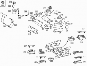 |
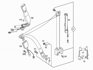 |
Front seat adjustment
The seat adjustment switches are located on the front doors.
- (1) Head restraint height
- (2) Seat height
- (3) Seat cushion tilt
- (4) Seat cushion depth
- (5) Seat fore and aft adjustment
- (6) Seat backrest tilt
To adjust the seat switch on ignition or open the respective door.
Seat fore and aft adjustment: Press the switch forward or backward in the direction of arrow (5). Adjust seat to a comfortable seating position that still allows you to reach the accelerator/brake pedal safely. The position should be as far to the rear as possible, consistent with ability to properly operate controls.
Seat cushion tilt: Press the switch up or down in the direction of arrow (3) until your upper legs are lightly supported.
Seat cushion depth: Press the switch forward or backward in the direction of arrow (4) until your legs are supported comfortably.
Seat backrest tilt: Press the switch forward or backward in the direction of arrow (6) until your arms are slightly angled when holding the steering wheel.
Seat height: Press the switch up or down in the direction of arrow (2).
Head restraint height: Press the switch up or down in the direction of arrow (1).
Head restraint tilt: Manually adjust the angle of the head restraint. Push or pull on the lower edge of the head restraint cushion.
Unoccupied front passenger seat automatic adjusting: The feature below is deactivated at the factory. If you wish to have it activated, use DAS. The front passenger seat head restraint automatically lowers after a few seconds when the front passenger seat is not occupied. This improves the driver's outward view as well as the forward view from the rear passenger compartment. When the front passenger seat is occupied again, the front passenger seat head restraint returns to the last set position within a few seconds. If the front passenger seat was moved fore or aft while not being occupied, the front passenger seat head restraint returns to a position that corresponds best with the seat’s axial position when the seat is occupied again.
Easy-entry/exit feature
With the easy-entry/exit feature activated, the steering wheel tilts upwards and the driver's seat moves to the rear. This allows easier entry into and exit from the vehicle when the driver’s door is opened. However, the engine must be turned off. When the SmartKey is inserted in the starter switch or you have pressed the KEYLESS-GO start/stop button once and the driver's door is closed, the steering wheel and the driver’s seat return to their last set positions.
You can activate the following functions:
- Steering column: Only the steering column is adjusted.
- Steering column and seat: The steering column and the seat are adjusted.
The easy-entry/exit feature can be switched on or off in the convenience submenu of the control system.
To cancel seat/steering wheel movement, do one of the following:
- Press the seat adjustment switch
- Move the steering column stalk
- Press the memory button
Lumbar support
For front seats basic lumbar support is available for vehicles without option code 404 - MULTI-CONTOUR SEAT, FRONT LEFT, 405 - MULTI-CONTOUR SEAT, FRONT RIGHT and 433 - LEFT DRIVING DYNAMICS SEAT 434 - RIGHT DRIVING DYNAMICS SEAT.
On rear seats basic lumbar support is available in vehicle with option code 223 - REAR BACK REST ADJUSTMENT AND HEAD RESTRAINTS, ELE.
You can adjust the contour of the seat's lumbar support to best support your spine. The thumbwheel for the driver's and front passenger's seat are located on the inner side of the seat.
Make sure the ignition is switched on. Set the lumbar support between 0 and 5.
Electric seat adjustment (ESA) function
Electric seat adjustment: The driver's and front passenger's seat are electrically adjustable. The adjustment takes place manually via the adjustment switches in the respective door control module. The ergo-function up to 31/05/2001 facilitates the adjustment. The individual seat positions can be stored and called up via the memory feature.
As of 01/06/2001 the ergonomics function is not used anymore for the front seat adjustment.
If the electrically adjustable rear bench seat is fitted (special equipment, model 220 only) the longitudinal position of the left and right halves of the seat bench can be adjusted manually using the adjusting switch in the respective door control module.
If electrically adjustable individual rear seats with memory are fitted (special equipment, model 220 only) likewise the longitudinal position and the backrest angle of the seat can be adjusted manually using the adjusting switches in the door control module. In addition it is possible to call up seat positions stored previously using the memory function
Electrically adjustable individual rear seats with memory: In addition it is possible to adjust the longitudinal position and the backrest angle of the front seat (front passenger's seat) via the door control module in the rear on the front passenger's side.
Entry/exit aid as of 01/09/2002 with code 275a: With the entry/exit aid the seat control module actuates the following control module when the key is removed:
- SAM/F (steering column)
- Overhead control panel (inside rearview mirror)
- Door control module (outside mirror)
The entry/exit aid enables the driver to get into and out of the vehicle more easily. Before the driver gets out the steering column is moved upwards and the seat is moved back. After getting in the position of the seat last adjusted is approached again or the last memory position is approached.
The driving position is stored key-dependent as is the memory position. Because of this if a key is changed a new driving position of seat, steering column and mirrors assigned to the key is adjusted. The entry/exit aid can be configured via the instrument cluster. The function can be switched off completely or partially (only the steering column is still active). On the V220 with individual rear seat system with code 275a the adjustment of a permanently defined position of the front passenger's and rear seat (park position) is possible from the rear door control module.
Adjusting front seats function
Block diagram for front seat adjustment:
Function requirements:
- No overvoltage or undervoltage
- Term.15R or 15 ON
- Respective vehicle door open
Adjusting front seats: The positions of the left and right front seat can be adjusted manually with the respective adjustment switches in the left front door control module (N69/1) and right front door control module (N69/2) in the driver's door and front passenger's door.
The following can be adjusted independently:
- The height of the head restraint
- The angle of the backrest
- The longitudinal position of the complete seat
- The position of the seat cushion
- The height of the rear half of the seat
- The height of the front half of the seat
Ergo function up to 31/05/2001:
The Ergo function up to 31/05/2001 facilitates manual adjustment. For this the seat adjustment must be correctly normalized.
Driver side: With the Ergo default setting, finding the right driver's seat position and the associated adjustments of the left and right outside mirrors, of the inside rearview mirror and steering column is facilitated. Once the default setting is complete only an individual fine adjustment is still necessary.
Passenger side: On the front passenger's side finding the correct front passenger's seat position is facilitated by the Ergo default setting.
As of 01/06/2001 the Ergo function is not used anymore, it is replaced by a further memory button.
Memory function up to 31/05/2001:
Using the memory feature, previously stored driver's and front passenger's seat positions can be approached automatically.
Driver side: On the driver's side two complete seat adjustments can be stored key-related and called up again. A total of eight memory areas are available. With the driver's seat adjustments the adjustments of the left and right outside mirrors, the inside rearview mirror and steering column are also stored.
Passenger side: On the front passenger's side two complete seat adjustments can be stored and called up again.
As of 01/06/2001 extended memory feature:
Driver side: On the driver's side three complete seat adjustments can now be stored and called up again for each transmitter key. Consequently a total of twelve memory areas are available. With the driver's seat adjustments the adjustments of the left and right outside mirrors, the inside rearview mirror and steering column are also stored.
Passenger side: On the front passenger's side three complete seat adjustments can be stored and called up again.
Seat adjusting motors position measurement function
Left and right front seat: The adjustment motors of the front seats - left front seat adjustment motor group with memory (M27)/right front seat adjustment motor group with memory (M28) have one Hall sensor for position measurement.
Electrically adjustable rear bench seat/individual rear seats (special equipment, model 220 only): The adjustment motors for the left rear seat adjustment motor group (M18/1)/right (M18/2) have one Hall sensor each for position measurement.
Position measurement: The signals from these Hall sensors are read in by the left front seat adjustment control module with memory (N32/1)/right front seat adjustment control module with memory (N32/2) and rear seats control module (N25/6, model 220 only), checked for plausibility and counted in the internal position counter. The received Hall pulses are evaluated as positive or negative according to the actuation voltage of the motor. A faultless position measurement is only possible in the normalized condition. It is a prerequisite for the ergonomics default setting function.
Seat calibration function
Function requirements:
- Voltage not too high or too low
- Seat adjustment switch is not pressed.
Through normalization in the left front seat adjustment control module with memory (N32/1)/right front seat adjustment control module with memory (N32/2) the counter counts of the position recognitions of the adjustment motors are linked to the actual positions.
The normalization is a prerequisite for easy entry (model 215 only) and the Ergo function up to 31/05/2001.
Performing normalization: Separate normalization is required for each adjustment motor. Normalization occurs by approaching the respective mechanical stop. Actuation must be carried out in this position for a further 250 ms at least.
Once normalization has been carried out, the control module must be still supplied with voltage for at least 5 seconds in order to ensure a complete and faultless storage in the non-volatile memory (EEPROM).
The mechanical stop relevant to the respective normalization:
| Provision for adjustment | Engine | left |
|---|---|---|
| Seat lengthwise adjustment | M27m1, M28m1 | front |
| Seat height adjustment rear | M27m2, M28m2 | top |
| Seat height adjustment front | M27m3, M28m3 | top |
| Head restraint adjustment | M27m4, M28m4 | DOWN |
| Backrest forward/back | M27m5, M28m5 | front |
| Seat cushion adjustment | M27m6, M28m6 | front |
Seat adjustment collision avoidance function
Function prerequisites:
- Normalizing performed
To avoid collisions of the seat with the seat adjustment switch, the center console, the B-pillar or the roof, the left front seat adjustment control module with memory (N32/1) and right front seat adjustment control module with memory (N32/2) have map controls. In this connection when the motors are actuated the maximum range of adjustment is restricted by means of performance maps stored in the control module and therefore avoid the seat colliding with an obstacle. The following possibilities of a collision can arise during seat adjustment depending on the current seat position:
| Collision possibilities | Actuation 1 | Actuation 2 |
|---|---|---|
| Cushion frame/Seat adjustment switch | Seat cushion angle down | Seat height adjustment down |
| Center console/Seat cushion | Seat lengthwise adjustment to the front | Seat cushion adjustment to the front |
| B-pillar Backrest | Seat forward/back adjustment to rear | Seat backrest adjustment to the rear |
| Roof Head restraint | (Backrest adjustment vertical) | Head restraint upwards |
Blocking detection function
The control modules constantly receive signals from the Hall sensors of the actuated motors. These signals are evaluated for position measurement. If the time intervals in which they enter the control module are too large or are missing completely, blocking is recognized and after t = 2 s actuation is interrupted. Only after the switch is released is a renewed actuation possible in this direction after t = 2 seconds. In comparison an actuation in the opposite direction is possible immediately.
Overload protection function
In order to prevent an overload, the left front seat adjustment control module with memory (N32/1)/right front seat adjustment control module with memory (N32/2) and rear seats control module (N25/6, model 220 only) measures the current of connected and actuated adjustment motors. If one of the currents exceeds a threshold value dependent on the supply voltage (I = 6.3 A - 16 A), the actuation is terminated immediately.
Front seat adjustment control module with memory
The left/right front seat adjustment control module with memory (N32/1,N32/2) is located under the seat cushion of the left/right front seat.
|
The left/right front seat adjustment control module with memory (N32/1,N32/2) connected to the CAN bus has the following tasks :
- Control of the six servo DC motors for the front seat adjustment motor group with memory (M27,M28)
- Position recognition of these motors
- Storage of the seat position by the memory feature as of 1.6.01 expanded by one memory location
- Calling up and approaching seat positions stored previously within the framework of the memory feature
- Approaching the permanently stored seat default settings depending on the longitudinal position of the seat within the framework of the Ergo function up to 31.5.01
- Control of heated seats/seat ventilation (special equipment)
- Control of the seat belt wearing comfort function
- Monitoring of backrest locking by the left/right front seat backrest release microswitch (S91/3,S92/3), (model 215 only)
In addition the control module is used for contacting of:
- Left/right front seat belt buckle restraint systems switch (S68/3,S68/4) with AB and GUS (only USA)
- Left/right front buckle microswitch (S68/9,S68/10)
- Left side control module - passenger seat occupied and child seat recognition sensor (B48) (right hand steering only)
- Right side control module - occupation recognition and automatic child seat recognition in front passenger's seat (B48) (left hand steering vehicle only)
- Left/right front multicontour backrest control module (N32/15,N32/16) (special equipment)
- Vehicle-sensitive seat belt lock sensor (A60), (model 215 only)
- Left /levtfront seat backrest angle microswitch group (S91/1,S92/1), (model 215 only)
The signal for the left/right front seat seat occupation is acquired by the left/right front seat adjustment control module with memory and is transmitted to the automatic air conditioning control and operating module via the interior bus (CAN B).
From this information the automatic air conditioning control and operating module increases, for example, the automatic blower level of the ventilation depending on the number of people in the vehicle.
Furthermore, the blower capacity adjusted in the automatic air conditioning control and operating module is read in by the left/right front seat adjustment control module with memory in order to adapt the seat ventilation by actuating the fans built into the seat
Front seat adjustment motor group
Location of front seat adjustment motor group, shown on model 220:
The six servo DC motors for adjusting the left/right front seat are actuated by the left front seat adjustment control module with memory (N32/1)/right front seat adjustment control module with memory (N32/2). They have one Hall sensor each for position recognition.
Multicontour seat function
Multicontour seats in front are installed in vehicles with option code 404 - MULTI-CONTOUR SEAT, FRONT LEFT and 405 - MULTI-CONTOUR SEAT, FRONT RIGHT.
Vehicles with individual rear seats option code 224 - INDIV.REAR SEAT AND HEAD RESTRAINTS, ELEC.ADJUSTAB have multicontour left/right individual rear seats. However, compared to front multicontour seats, the individual rear seats lack air cushions in the shoulder region.
Operation of front multicontour backrest
The multicontour backrest has inflatable air cushions built into the seat backrest to provide additional lumbar and side support.
The seat backrest cushion height and curvature can be continuously varied with switches on the right side of the seat after turning the SmartKey in the starter switch to position 2 or pressing the KEYLESS-GO start/stop button twice.
- (1) - Shoulder region support
- (2) - Side bolster adjustment
- (3) - Massage function (PULSE)
- (4) - Lumbar region support
Make sure the ignition is switched on.
Shoulder region support: Press "+" or "-" on switch (1). The air cushion inflates or deflates.
Lumbar region support: Press "down" or "up" on rocker switch (4). This selects the air cushion you wish to adjust. Press "+" or "-" on switch (4). The air cushion inflates or deflates.
Side bolsters adjustment: Adjust the side bolsters so that they provide good lateral support using switch (2).
When the engine is turned off, the last cushion setting is retained in memory, and the cushion is automatically adjusted to this setting when the engine is restarted.
Massage function (PULSE): You can reduce muscle tension during long trips by periodically using the massage function. Press button (3). The indicator lamp on button (3) comes on. The air cushions in the lumbar region inflate and deflate rhythmically. The massage function switches off automatically after approximately eight minutes. The indicator lamp extinguishes.
Multicontour seat function
Illustration shows multicontour seat (MCS):
|
The multicontour backrest of the multicontour seat enables individual adjustment of the seat backrest by filling and venting a total of seven air cushions. The contour and surface hardness of the seat backrest can be adjusted independently of each other. For this (combined into groups) two air cushions each are used for the shoulder region (1) and the side region (2), as well as three air cushions for the lumbar region (3). The filling and emptying of the individual air cushion groups is controlled either manually, by means of the operating switch (4) in the seat cushion frame of the respective seat, or automatically by means of the multicontour backrest control module, if the function of dynamic lumbar support has been performed.
The storage and calling up of seat backrest adjustments (air cushion pressure values) is possible with the memory feature. As of 01/06/2001 the switch group has a different design. The modifications are shown in the multicontour switch section below.
Multicontour seat control module
The left front multicontour backrest control module (N32/15)/the right front multicontour backrest control module (N32/16) is located under the respective seat.
The rear multicontour backrest control module (N32/14) is located under the right half of the rear seat bench.
Apart from the actuation/evaluation electronics, pressure control valves (one for each air cushion) are located in all control modules of the multicontour backrests. The air cushions are filled and emptied via these pressure control valves.
The control module reads in the switch conditions of the switch groups of the multicontour backrests, detects the air pressure in the air cushions via piezoresistive pressure sensors, actuates the pressure control valves and receives/sends data from/ to the respective seat control module.
|
|
The multi-contour backrest control module is responsible for:
- Inflating and deflating the multi-contour backrest according to the control actions read in from the multi-contour backrest switches
- Control of dynamic lumbar feature, actuated with multi-contour backrest switch "PULSE" button
- Sensing of actual pressure values in air cushions with piezoresistive pressure sensors
- Generating status data logs on the cushion inflation and transferring these logs to the associated seat control module via a bidirectional, serial interface.
In context with the memory feature:
- Communication with the corresponding control module via interface, particularly regarding storage and recall of stored seat positions
- Setting stored seat positions (pressure values) and other settings when the memory feature is called
Multicontour seat switches
The switch train for the front right (S108)/front left (S109)/rear right (S103)/rear left (S104) multi-contour backrest is located in the corresponding seat, on the outer side of the seat cushion frame.
|
The switch can be used for manually inflating and deflating lumbar cushion group, side backrest cushions and also, on front seats only, shoulder cushion group. An additional switch serves for activating and deactivating the dynamic lumbar adjustment feature.
The switch positions are voltage-coded by means of resistors. The coded voltages are then read in by the corresponding multi-contour backrest control module.
Front seat switch
The switch train in the left/right front seat is equipped with a rocker switch for controlling shoulder cushion and lumbar cushion pulsation. A further rocker switch is used to control the inflation and deflation of the two seat backrest cushions for lateral support. A "PULSE" button is additionally available for switching the dynamic lumbar support on and off.
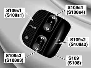 |
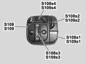 |
|
Rear seat switch
The switch train in the left/right rear individual seat is equipped with a rocker switch for controlling lumbar support cushion pulsation. A further rocker switch is used to control the inflation and deflation of the two seat backrest cushions for lateral support. A "PULSE" button is additionally available for switching the dynamic lumbar support on and off.
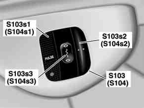 |
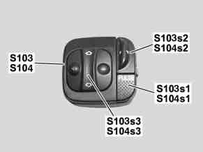 |
|
Adjust front multicontour seats function
Block diagram for multicontour backrest of front seats:
|
Function requirements:
- Circuit 15c or circuit 15R ON
- respective door open for t >20 s
- Multicontour backrest control module activated:
The left front multicontour backrest control module (N32/15)/right front multicontour backrest control module (N32/16) is activated when it receives an enable signal via a discrete line from the left front seat adjustment control module with memory (N32/1)/right front seat adjustment control module with memory (N32/2).
Manual adjusting of the air cushion groups in the multicontour backrest
The switch conditions of the multicontour backrest switch group in the left front seat (S109)/and right front seat (S108) are read in by the left front multicontour backrest control module (N32/15)/right front backrest control module (N32/16). As a result of this the control module fills and empties the corresponding air cushion groups for as long as the switch is pressed and the function prerequisites are met. At the same time data are exchanged between the relevant control module and the left front seat adjustment control module with memory (N32/1)/right front seat adjustment control module with memory (N32/2) via a discrete line so that storage and subsequent calling up of air cushion adjustments performed manually is possible via the memory feature.
Automatic adjustment of the air cushion groups in the multicontour backrest via the memory feature
The storage and calling up of adjustments performed manually is triggered and controlled by the left front door control module (N69/1)/right front door control module (N69/2). To do this, the door control module exchanges information with the relevant seat control module via CAN messages.
If this receives the request to store, the pressure values of the air cushions conveyed from the multicontour backrest control module are stored in its non-volatile memory. If there is a later request from the door control module to call up memory items, the stored air cushion pressure values are provided to the multicontour backrest control module again. Thereupon this control module fills/empties the air cushions as per the stored values.
As of 01/09/2002 codes 344 and 343 the left front dynamic seat control module (N32/19) and right front dynamic seat control module (N32/22) are responsible for the memory feature.
Manual adjustment of air cushions in the multicontour seat
Function requirements:
- Circuit 15R ON
- Circuit 15 ON
The air cushions of the multicontour backrest can be adjusted manually via the right rear/left rear multicontour backrest switch (S103, S104) and right front/left front multicontour backrest switch group (S108, S109) in the seat cushion frame (on the outside) of the respective seat - right rear/left rear/right front/left front. The adjustments of the air cushions assumed for the shoulder region, the lumbar support region and the seat backrest lateral support are stored in a volatile memory by the left front multicontour backrest control module (N32/15)/ and right front multicontour backrest control module (N32/16) and rear multicontour backrest control module (N32/14)
These values can be stored and called up again via the memory feature in the non-volatile memory of the relevant seat control module.
 |
 |
Manual adjustment of the shoulder region (up to 31/05/2001)
Manual adjustment of the shoulder region by switch for the shoulder region (S103s4/S104s4).
For driver's and front passenger's seat only. This provision for adjustment is not realized for the individual rear seats.
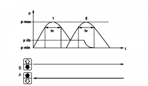 |
|
Pressing the bottom half of the switch: Air cushions 1 and 2 of the shoulder region are filled in sequence from top to bottom up to the maximum pressure and then emptied again down to the minimum pressure. The process stops as soon as air cushion 2 is at minimum pressure.
Pressing the top half of the switch: The air cushions are filled in the reverse order, thus from the bottom upwards and then emptied (see above).
The transfer pressure p üb and the dwell period tv are adjustable.
Manual adjustment of the shoulder region (as of 01/06/2001)
When the rocker switch is pressed towards "+" or "-" the backrest contour in the shoulder region is changed by filling/emptying the air cushions.
This provision for adjustment is not realized for the individual rear seats.
Manual adjustment of the lumbar support region (up to 31/05/2001)
Manual adjustment of the lumbar support region by the rear left/right lumbar support adjustment switch (S103s3/S104s3) and front right/left lumbar support adjustment switch (S108s3/S109s3).
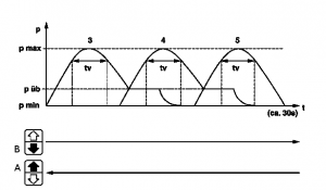 |
|
Pressing the bottom half of the switch: Air cushions 3, 4, 5 of the lumbar support region are filled from top to bottom up to the maximum pressure and then emptied again down to the minimum pressure. The process stops as soon as air cushion 5 has reached the minimum pressure.
Pressing the top half of the switch: The air cushions are filled in the sequence 5, 4, 3, so from top to bottom and then emptied again (see above).
The transfer pressure p üb and the dwell period tv are adjustable.
Manual adjustment of the lumbar support region (as of 01/06/2001)
When the cross rocker is pressed towards "+" or "-" the backrest contour changes in the lumbar support region by filling/emptying the air cushion which is currently active.
When the cross rocker of the bottom half of the switch is pressed the backrest contour in the lumbar support region is changed sequentially. Only one air cushion is actuated actively in this process. When the cross rocker of the top half of the switch is pressed the sequence is the same as when the bottom half of the switch is pressed, only in the reverse order.
Dynamic lumbar support of multicontour backrest
In order to prevent stresses in the back on longer journeys, the multicontour backrest is equipped with the dynamic lumbar support function. The function is controlled in the relevant seat by the multicontour backrest control module. It is triggered by pressing "PULSE" button on the dynamic lumbar support adjustment switch (S103s1/S104s1/S108s1/S109s1) in the left rear/right rear multicontour backrest switch group (S103, S104) and right front/left front multicontour backrest switch group (S108, S109).
Lumbar support: curvature of spine in lumbar region.
Starting with the air cushion which is currently active the pulsation occurs alternately in the two lumbar support cushions in the sequence lower and upper lumbar (sequence is parameterizable). Filling starts with the active lumbar support cushion up to the next pressure level, unless the upper pressure level has already been reached or exceeded. Each air pressure adjustment is held for approx. 10 seconds before the next condition is assumed. After approx. 8 minutes the program is terminated automatically and the original air cushion pressures are reproduced.
Illustration shows function sequence for dynamic lumbar support:
First of all the three lumbar support air cushions of the multicontour backrest are emptied. After this the center air cushion is filled in stages up to the maximum pressure and then emptied again down to the minimum pressure (see Figure). This process (cycle) is repeated for a second time. After this the function is terminated by the control module. The function can be terminated at any time by pressing the switch again.
Retrofitting multicontour backrest
Multicontour backrest option can be easily retrofitted. The only parts needed are multicontour backrest, multicontour control module and switch from the donor vehicle. For installation instructions on facelift vehicle see the instructions below. Installation may require to modify the fitting on the overpressure reservoir.
Dynamic seat function
Dynamic seat (drive-dynamic seat) function available as of 01/09/2002 on vehicles equipped with option code 433 - LEFT DRIVING DYNAMICS SEAT and 434 - RIGHT DRIVING DYNAMICS SEAT.
The drive-dynamic seat automatically adjusts the lateral support provided by the seat backrest to your driving style.
To activate drive-dynamic function press button (1).
The indicator lamp in the switch comes on and the following message appears in the multifunction display for five seconds:
The drive-dynamic seat electronically controls the air pressure in the air chambers of the seat backrest side bolsters. This function improves driving comfort and pleasure.
You can adjust the characteristics of the drive-dynamic seat using the control system.
Illustration shows Dynamic seat (FDS) as of 01/09/2002 with codes 433 and 434:
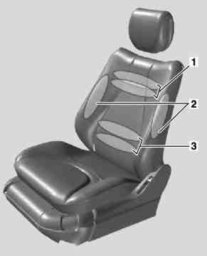
|
|
All the following provisions for adjustment are explained on the driver's seat and also apply to the front passenger's seat.
The dynamic seat comprises the functions:
- Memory multicontour backrest (MMKL)
- Dynamic side support
Memory multicontour backrest (MMKL)
The multicontour backrests enable individual adjustment of the respective seat backrest by filling and emptying up to three air cushion groups:
- Air cushion for the upper and lower shoulder region
- Air cushion for the respective side region
- Air cushion for the upper and lower lumbar support region
The "Dynamic lateral support" function is switched on or off by pressing the FDS "DYNAMIC" button and is controlled by the left front dynamic seat control module (N32/19). If the function is activated, this is displayed by an LED in the FDS "DYNAMIC" button. The left front dynamic seat control module (N32/19) adjusts after that a corresponding basic pressure in the lateral support cushions and, when cornering, ensures better retention in the lateral support by temporarily adding pressure to the lateral support cushions on the outside of the curve. This essentially happens as a function of the instantaneous speed and the lateral acceleration. This information comes from the traction systems control module (N47) and is transmitted by central gateway control module (N93) from CAN-C (engine compartment) to CAN-B (interior). If the data for the FDS function fail for more than 2 seconds, the function is switched off and remains switched off. The extent and speed with which the lateral support cushions for the driver's and front passenger's seat are filled can be adjusted via the second operating level of the instrument cluster (A1).
Priority sequence of the functions
The priorities are set in the sequence:
- Priority 1 Lumbar support
- Priority 2 Shoulder region (not for individual rear seats)
- Priority 3 Lateral support
- Priority 4 Dynamic lumbar support and dynamic lateral support (front seats only)
When pressing multiple rocker switches at the same time, only the adjustment movement with the highest priority is executed.
Abort criteria
All functions are interrupted if there is overvoltage or undervoltage. The relevant function is not performed if a valve has overheated or there is a leakage fault.
Limit stop emptying
If the end point is reached after the lumbar support wave has passed, the inactive air cushion is emptied for as long as the switch is pressed, but for a maximum period of 1 minute.
Control functions
The adjusted specified pressures of the individual cushion areas are controlled by the left front dynamic seat control module (N32/19) and right front dynamic seat control module (N32/22) in each case in a manner which is unnoticeable for the customer provided that the function conditions for manual adjustment are met.
The contour and surface hardness of the seat backrest can be adjusted manually via the:
- Switch group for right front multicontour backrest (S108)
- Switch group for left front multicontour backrest (S109)
- the "dynamic lumbar support" function.
Dynamic lateral support (driver's/front passenger's seat)
Function requirements:
- Circuit 15R ON
- Circuit 15 ON
- No undervoltage or overvoltage
- No overtemperature sensor
- No leakage fault in the lateral support region
Sport (stage 1): Extra pressure is applied more quickly and more intensely to the lateral support cushions on the outside of the curve.
Comfort (stage 2): Extra pressure is applied slowly and less intensely to the lateral support cushions on the outside of the curve.
Definitively the following control modules are involved in the dynamic seat:
- left front dynamic seat control module (N32/19)
- right front dynamic seat control module (N32/22)
- central gateway control module (N93)
- traction systems control module (N47)
Background functions
In the lumbar support region the cushions are arranged overlapping and consequently coupled in their function during the wave sequence. As only one air cushion is active in each case, the adjacent cushions are considered as not active i.e. empty. The following background functions are necessary to ensure this.
Idle time emptying (optional)
While the pressure is kept constant in the active air cushion (residence time), the adjacent non-active air cushions are emptied.
Backgrounds emptying
If the active air cushion is emptied, then the residual pressure in the adjacent non-active air cushions is also reduced, as soon as the air cushions have the same pressure.
The subsequent regulation follows, for example, in the event of pressure deviations caused by:
- The respective person sitting in or leaning on the seat
- Leakage in the seat inflators
- Temperature changes caused by heated seats, insolation, air conditioning and user warmth
Sudden changes in pressure which arise due to the person sitting in on leaning on the seat are adjusted immediately and in a comfort- orientated manner. The control parameters that are listed can be programmed using diagnosis.
Dynamic seat control module
The left front dynamic seat control module (N32/19) and right front dynamic seat control module (N32/22) is located in the respective seat backrests on the driver's/front passenger's side.
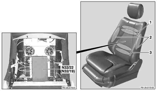
|
|
Tasks:
- To fill and empty the multicontour backrest in accordance with the requirements read in by the switch
- Control of dynamic lumbar support, triggered by the multicontour backrest switch with the inscription: "PULSE"
- Control of dynamic lateral support triggered by the "DYNAMIC" switch
- Detection of the actual pressure values of the air cushions by piezoresistive pressure sensors and keeping these pressures constant
- Reading in the voltage-coded MMKL adjusting switch and the DYNAMIC switch
- Communication with the interior CAN via the respective seat control module
- Adjusting the stored pressure values when calling up the memory feature and storing the actual contours
- Cutout of the respective function if the pressure control valve responsible has overheated
Dynamic seat switch
The right/left front DS [FDS] switch group (S108/1,S109/1) in each case is located under the front multicontour backrest switch group on the seat cushion.
The switch turns the dynamic lateral support function on and off.
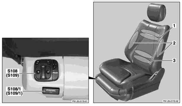
|
|
Manual adjustment of air cushions in the dynamic multicontour seat
All the following provisions for adjustment are explained on the driver's seat and also apply to the front passenger's seat.
Manual adjustment of the shoulder region as of 01/09/2002 with codes 433 and 434
Air cushions 1 and 2 of the shoulder region are coupled and are adjusted with the shoulder region adjustment switch (S109s4).
When the rocker switch is pressed towards "+" or "-" the backrest contour in the shoulder region is changed by filling/emptying the air cushions.
Manual Adjustment of the lumbar support region as of 01/09/2002 with codes 433 and 434
The lumbar support region of the seat is operated by the lumbar support adjustment switch (S109s3). When the cross rocker is pressed towards "+" or "-" the backrest contour changes in the lumbar support region by filling/emptying the air cushion which is currently active.
When the cross rocker of the bottom half of the switch is pressed the backrest contour in the lumbar support region is changed sequentially. First, the lower air cushion is filled/emptied again and then the upper air cushion is filled. Only one air cushion is actuated actively in this process. This sequence starts with the air cushion which has just become active.
When the cross rocker of the top half of the switch is pressed the sequence is the same as when the bottom half of the switch is pressed, only in the reverse order. The upper air cushion is emptied first and then the lower air cushion is filled.
Dynamic lumbar support
All the following provisions for adjustment are explained on the driver's seat and also apply to the front passenger's seat.
In order to prevent stresses in the back on longer journeys, the dynamic seat multicontour backrest is equipped with the dynamic lumbar support function. The function is controlled in the relevant seat by the multicontour backrest control module. It is triggered by pressing "PULSE" button on the dynamic lumbar support adjustment switch (S103s1/S104s1/S108s1/S109s1) in the left rear/right rear multicontour backrest switch group (S103, S104) and right front/left front multicontour backrest switch group (S108, S109).
Lumbar support: curvature of spine in lumbar region.
Starting with the air cushion which is currently active the pulsation occurs alternately in the two lumbar support cushions in the sequence lower and upper lumbar (sequence is parameterizable). Filling starts with the active lumbar support cushion up to the next pressure level, unless the upper pressure level has already been reached or exceeded. Each air pressure adjustment is held for approx. 10 seconds before the next condition is assumed. After approx. 8 minutes the program is terminated automatically and the original air cushion pressures are reproduced.
Illustration shows function sequence of dynamic lumbar support as of 01/09/2002 with codes 433 and 434:
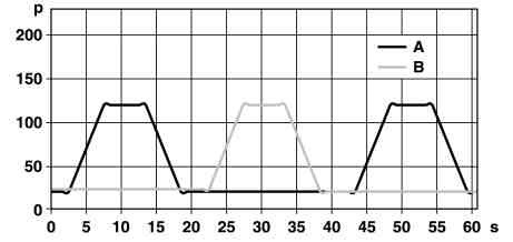
|
|
The function is controlled by the left front dynamic seat control module (N32/19). The program is started and stopped by the dynamic lumbar support adjustment switch (S109s1) "PULSE" button. The active function is displayed by illuminating the LED in the switch. After the switch is pressed, first the air pressures of the air cushion in the lumbar support region are stored by the left front dynamic seat control module (N32/19).
Remove/install front seat belt buckle (up to 31/08/2002)
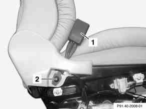
|
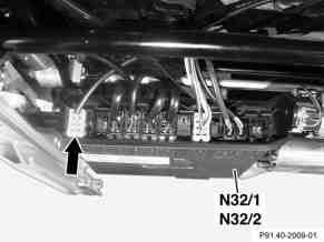
|
|
- Remove front seat
- Open cable straps of seat belt buckle switch cable on underside of seat
- Remove coupling (arrow) from left (N32/1) and right (N32/2) front seat adjustment control unit with memory
- Unscrew seat belt buckle screw (2) and remove seat belt buckle (1)
- Install in the reverse order
Torque specifications:
- Screw/nut on front seat belt buckle: 30 Nm
Remove/install front seat belt buckle (as of 01/09/2002)
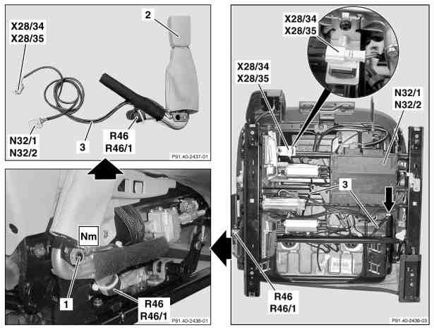
|
|
- Switch ignition off, withdraw ignition key
- Switch off engine, remove transmitter card from the vehicle (with keyless go code 889). Keep transmitter key outside transmission range.
- Remove front seat
- Unscrew nut (1) from seat belt buckle (2)
- Disconnect and expose wiring harness (3) with yellow connectors (see arrow and magnification) to left (N32/1) and right (N32/2) front seat adjustment control unit with memory and to 2-pin driver (X28/34) and front passenger (X28/35) seat buckle emergency tensioning retractor connector separation point
- Remove seat belt buckle (2) with driver (R46) and front passenger (R46/1) buckle ETR (R46) from front seat. If seat belt buckle (2) with driver (R46) and front passenger (R46/1) buckle ETR is replaced, the defective part must be properly disposed.
Torque specifications:
- Screw/nut on front seat belt buckle: 30 Nm
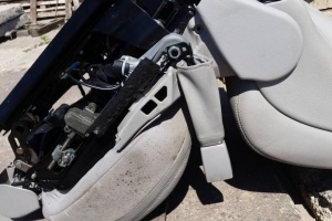 |
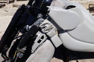 |
Remove/install front seat belt (up to 31/08/2002)
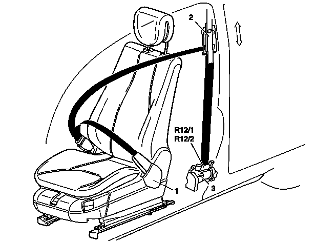
|
|
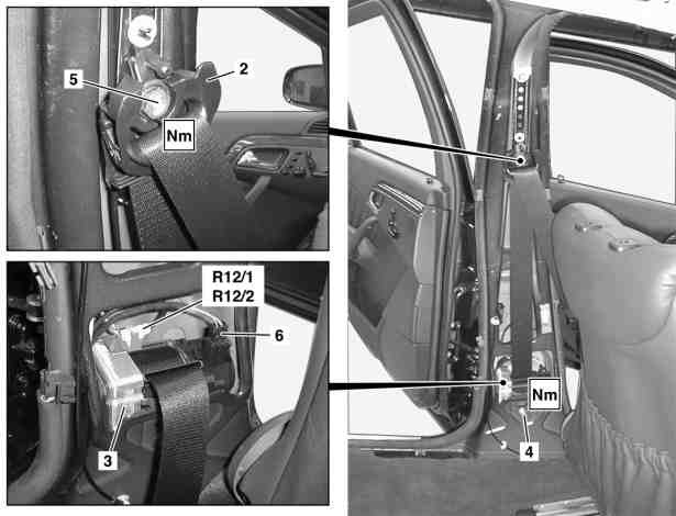
|
|
- Move front seat as far forward as possible with backrest upright
- Switch ignition off, withdraw ignition key
- Switch engine off, remove transmitter key from vehicle. With KEYLESS-GO code 889 keep transmitter key outside transmission range.
- Remove paneling on B-pillar
- Remove cover of belt end fitting (1) and undo screw
- Unscrew nut (5) from seat belt guide bracket (2)
- Release coupling on driver ETR [GUS] ignition squib (R12/1), passenger-side ETR [GUS] ignition squib (R12/2) and coupling (6)
- Remove screw (4) at automatic seat belt retractor (3)
- Remove automatic belt reel (3). Installation: Note different version (left/right) of seat belt emergency tensioning retractor and correct seating in catch. Noises from the automatic belt reel when rolling up belt are normal. The only available response to negative customer feedback regarding unacceptable noise levels is to replace the seat belt assembly with emergency tensioning retractor in its entirety. On no account should oil or grease be used to help eliminate noise. Automatic belt retractors that have been opened are no longer under warranty! If the seat belt with emergency tensioning retractor has been replaced, the defective unit must be disposed of properly.
- Install in the reverse order
- Carry out diagnosis
Torque specification:
- Belt end fitting screw: 30 Nm
- Screw/nut on front seat belt guide bracket: 30 Nm
- Screw on front automatic belt reel: 30 Nm
Remove/install front seat belt (as of 01/09/2002)
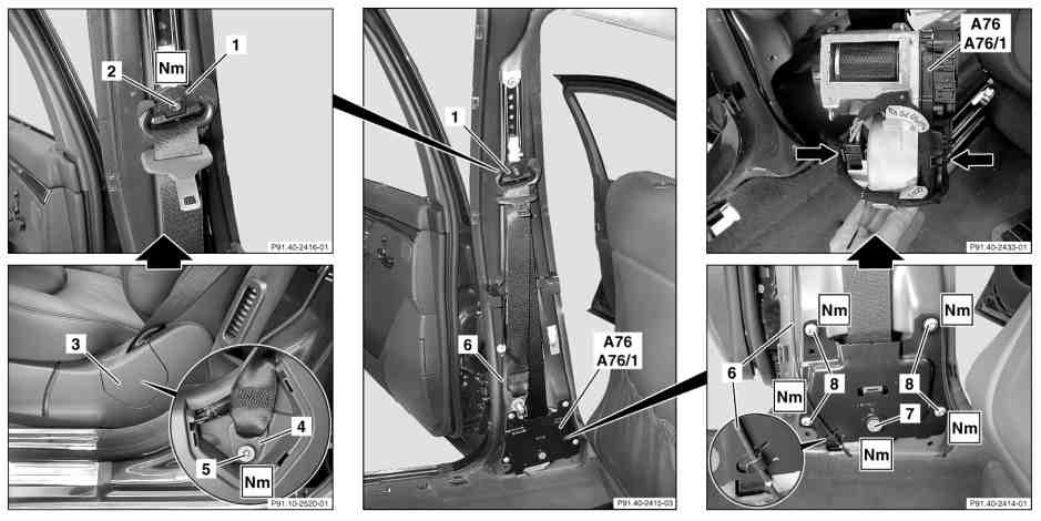
|
|
- Move front seat as far forward as possible with backrest upright
- Switch ignition off, withdraw ignition key
- Switch engine off, remove transmitter key from vehicle. With KEYLESS-GO code 889 keep transmitter key outside transmission range.
- Remove paneling on B-pillar
- Remove cover (3) of belt end fitting (4) and undo screw (5)
- Unscrew screw (2) from seat belt guide bracket (1)
- Unhook Bowden cable (6) on cover plate (see magnifying glass at bottom right)
- Undo TORX screw (8, 4 pieces) on cover plate. Installation: Tighten screw (7) to torque rating.
- Undo screw (7) from cover plate. Installation: Tighten screw (7) finger-tight only to cover plate.
- Detach 6-pin coupling and 2-pin coupling (see arrows) of left front reversible emergency tensioning retractor (A76), and right front reversible emergency tensioning retractor
- (A76/1) Remove left front reversible emergency tensioning retractor (A76), and left front reversible emergency tensioning retractor (A76/1). Installation: Note different version (left/right) of seat belt emergency tensioning retractor and correct seating in cover plate. Noises from the automatic belt reel when rolling up belt are normal. The only available response to negative customer feedback regarding unacceptable noise levels is to replace the seat belt assembly with emergency tensioning retractor in its entirety. On no account should oil or grease be used to help eliminate noise. Automatic belt retractors that have been opened are no longer under warranty!
- Install in the reverse order
- Carry out diagnosis
Torque specification:
- Belt end fitting screw: 30 Nm
- Screw/nut on front seat belt guide bracket: 30 Nm
- Screw on front automatic belt reel: 30 Nm
- Bolt, emergency tensioning retractor cover plate to B-pillar: 10 Nm
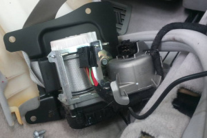
Remove/install front seat belt height adjustment mechanism
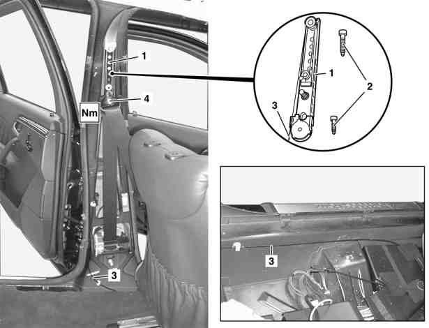
|
|
- Remove front seat
- Remove paneling on B-pillar
- Unclip Bowden cable (3) using Omega clip
- Unclip Bowden cable (3) from deflection in cable duct. Lift floor lining at left front until the deflection for the Bowden cable (3) in the cable duct can be easily accessed.
- Disassemble the Bowden cable (3) up to the belt height adjuster (1)
- Undo nut from seat belt guide bracket (4)
- Undo screw (2, 2 pieces) on belt height adjuster (1)
- Install in the reverse order
Torque specification:
- Screw/nut on front seat belt guide bracket: 30 Nm
- Screw on front automatic belt height adjuster: 25 Nm
Remove/install front seat backrest seat-back lining
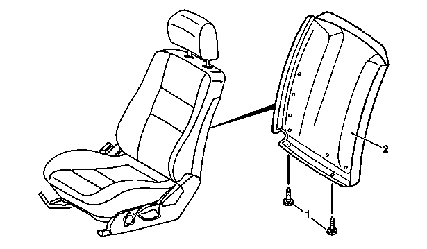
|
|
- Slide the front seat forwards with the longitudinal adjustment mechanism
- Slide backrest forwards with the inclination adjustment mechanism
- Unscrew screws (1)
- Pull seat-back lining (2) down and take off. Installation: slide seat-back lining into top of backrest.
- Install in the reverse order
Backrest seat-back lining is interchangeable between left and right seat backrest.
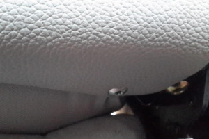 |
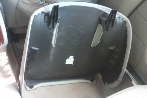 |
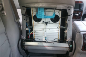 |
Remove/install front seat head restraints
Adjust head restraint so that the center of the head restraint supports the back of the head at eye level. This will reduce the potential for injury to the head and neck in the event of an accident or similar situation. Do not drive the vehicle without the seat head restraints. Head restraints are intended to help reduce injuries during an accident.
Tilt the seat backrest to the rear for easier removal and installation of the head restraints.
Removing front head restraints
Press switch (1) upwards and hold until the head restraint is fully extended. Pull out head restraint.
Installing front head restraints
- Press switch (1) upwards and hold for about five seconds.
- Push the head restraint down until it engages.
- Adjust head restraint to desired position.
Remove/install head restraint upholstery (up to 31/08/2002)
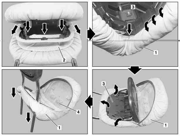
|
|
- Remove head restraint and place on suitable surface
- Completely unfold head restraint
- Remove expansion element (2). Unclip expansion element (2) at first on guide rods on opposite side, then withdraw downwards.
- Remove upholstery (1) in hinge area at left and right on housing (3)
- Remove upholstery (1) from clip groove on housing (3)
- Slide upholstery (1) on guide rods downwards and remove
- Install in the reverse order
Remove/install headrest guide on front seat
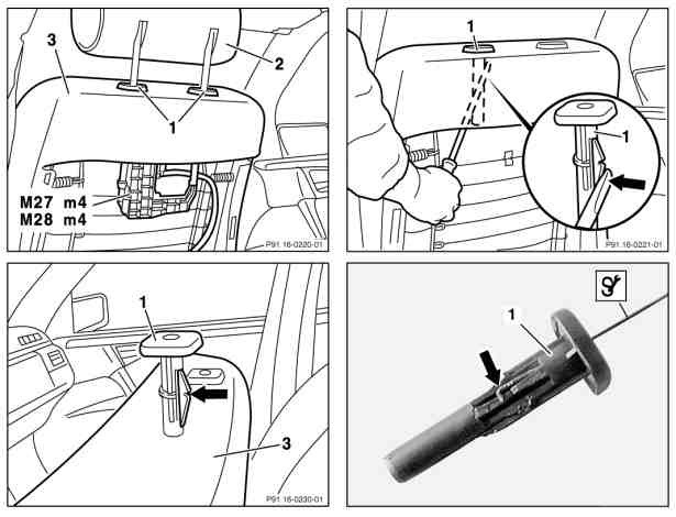
|
|
Remove:
- Remove head restraint (2)
- Remove tensioning element (seat-back lining) from front seat backrest
- Remove head restraint raise/lower motor (M27m4/M28m4). Push motor to right first and then remove downwards.
- Release catch at head restraint guide (1) using screwdriver. Push back catch (arrow) at head restraint guide (1) using screwdriver and pull head restraint (1) out upwards.
- Release catch at head restraint guide (1) using pulling hook. Insert pulling hook into top of head restraint guide (1), push back catch and pull out head restraint upwards.
Install:
- Insert head restraint guide (1) into backrest frame of front seat backrest (3). Do not damage backrest upholstery. Catch (arrow) must point towards rear.
- Engage head restraint guide (1) in backrest frame of front seat backrest (3)
- Install head restraint raise/lower motor (M27m4/M28m4). Insert motor facing upwards and then push to left until it engages in backrest frame.
- Fit seat-back lining to front seat backrest (3)
- Install head restraint (2)
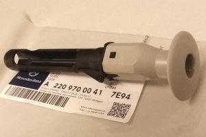
| Error Code | Generated By | Description |
|---|---|---|
| B1203 | ESA-FL - Electronic seat adjustment front left | Hall sensor of component M27m4 (Head restraint raise/lower motor) is faulty |
Facelift head restraint motor A2209700026 fits both sides.
Note: due to normalization requirement, when installing new motor the new motor may be need to be moved manually to the position of the old motor, otherwise it may be encountered that motor is not able to move the full distance.
Remove/install front seat (up to 31/08/2002)
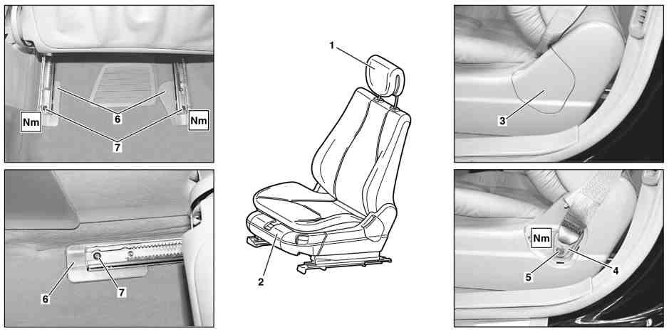
|
|
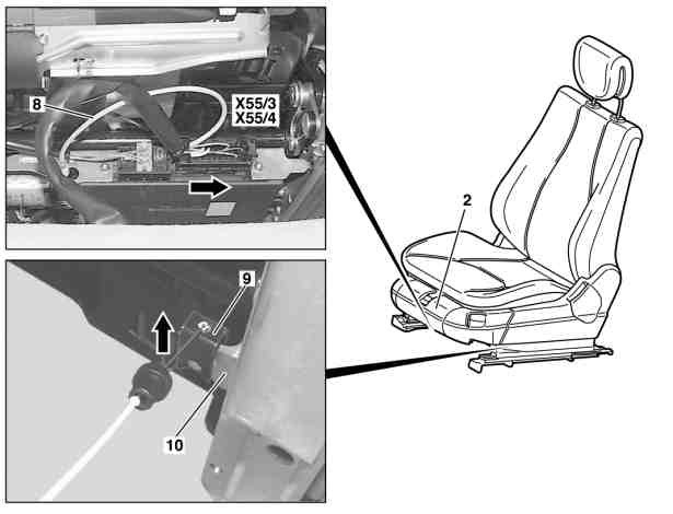
|
|
- Remove head restraint (1)
- Adjust front seat (2) to front
- Remove cover (3) above belt end fitting (4)
- Remove bolt (5) from seat belt end fitting (4)
- Remove screws (7) at the back of the seat rails
- Remove covers (6) at rear of seat rails
- Position front seat (2) to rear
- Remove screws (7) at the front of the seat rails
- Remove covers (6) at front of seat rails
- Detach plug connection from pneumatic line (8) and left front seat connector block (X55/3) and right front seat connector block (X55/4) from front seat cushion. Disconnect plug connection on pneumatic line (8) with 7 mm open end wrench.
- Detach retaining clamp (9) for Bowden cable seat belt height adjustment at seat adjustment mechanism (10) in direction of arrow
- Lift front seat (2) and remove
- Install in the reverse order
Torque specification:
- Bolt to seat runner: 50 Nm (up to 30/11/2001), 45 Nm (as of 01/12/2001)
- Screw on belt end fitting: 30 Nm
Remove/install front seat (as of 01/09/2002)
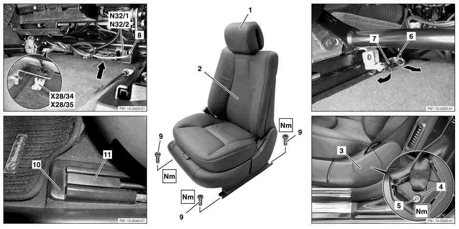
|
|
- Switch off ignition, remove ignition key (vehicles without KEYLESS-GO, code 889).
- Switch off engine, remove transmitter key from vehicle (with KEYLESS-GO, code 889). Keep transmitter key out of transmitter range.
- Remove head restraint (1)
- Adjust front seat (2) to front. Move front and rear seat cushions all the way up. Move backrest into upright position.
- Remove cover (3) at rear side paneling
- Remove screw/bolt (5) at belt end fitting (4). Installation: When screwing on, ensure that belt end fitting (4) remains mobile.
- Remove rear screws/bolts (9) from seat rails. Remove cover (11) from seat rail.
- Turn retaining clamp (7) at Bowden cable in direction of transmission tunnel and remove
- Unhook grommet (6) with Bowden cable from bracket
- Position front seat (2) to rear
- Remove front screw/bolt (9) from seat rails. Remove cover (11) from seat rail.
- Pry off pneumatic line plug coupling (8) with open end wrench, size 7. Slightly incline seat toward rear in vehicle.
- Detach connecting coupling (see arrow) from front seat adjustment control unit with memory, left (N32/1), right (N32/2). Slightly incline seat toward rear in vehicle.
- Disconnect 2-pin driver seat connecting point buckle emergency tensioning retractor connector (X28/34), 2-pin front passenger seat connecting point buckle emergency tensioning retractor connector (X28/35). Slightly incline seat toward rear in vehicle.
- Remove seat rail final cover (10) from seat rails
- Lift front seat (2) and remove
- Install in the reverse order
- Check function of seat adjustment mechanism
Torque specifications:
- Bolt to seat runner: 45 Nm
- Screw on belt end fitting: 30 Nm
Turn retaining clamp (7) at Bowden cable in direction of transmission tunnel and remove Unhook grommet (6) with Bowden cable from bracket
 |
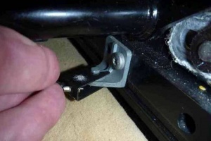 |
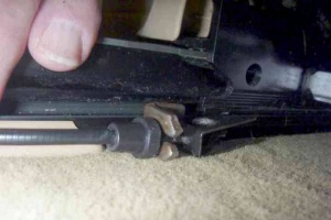 |
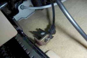 |
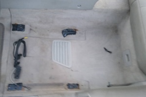 |
 |
Remove/install front seat backrest (up to 31/08/2002)
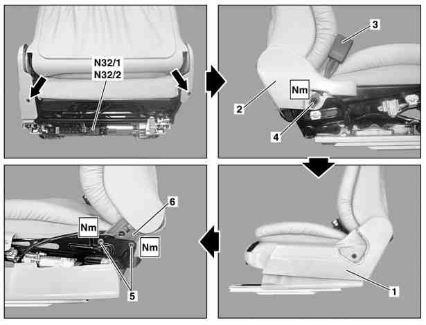
|
|
- Remove front seat
- Remove screw (arrow) on paneling (1)
- Remove trim panel (1)
- Remove bolt (4) and remove seat belt buckle (3)
- Remove screw (arrow) on paneling (2)
- Remove trim panel (2)
- Separate pneumatic line connector for lumbar support air cushion
- Remove multicontour backrest control unit from front seat (on vehicles with driver seat multicontour backrest, code 404b and passenger seat, code 405b).
- Disconnect backrest and head restraint adjustment connector from left front seat adjustment control unit with memory (N32/1) and right front seat adjustment control unit with memory (N32/2)
- Unscrew bolt (5, 2 each) from left and right backrest fitting (6)
- Remove front seat backrest from the seat adjustment mechanism
- Install in the reverse order
Torque specifications:
- Bolt at backrest fitting: 35 Nm (up to 30/11/2001 and as of 01/12/2001)
- Screw/nut on front seat belt buckle: 30 Nm
Remove/install front seat backrest (as of 01/09/2002)
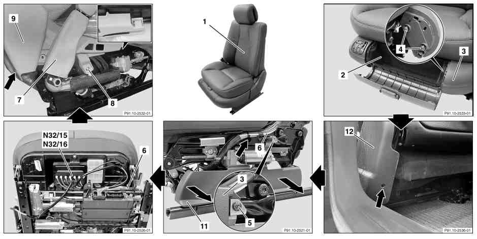
|
|

|
|
- Remove front seat
- Open flap on stowage compartment (2)
- Unclip stowage compartment (2)
- Remove fire extinguisher (for fire extinguisher code 682)
- Remove bolts (4, 2 pieces) on the left side paneling (3)
- Unscrew and remove bolt (see arrow) on the belt end fitting cover (12)
- Unscrew bolt (5) on the left side paneling (3) (see enlarged detail)
- Detach left side paneling (3) in direction of travel
- Unclip lower side paneling (11) in the direction of the arrow (for the multicontour backrest for the driver seat code 404b and front passenger seat code 405b).
- Remove multicontour backrest control unit on front seat (for the multicontour backrest for the driver seat code 404b and front passenger seat code 405b).
- Remove bolt (see arrow) and bolt (8) on seat belt buckle (9) cover
- Unclip retaining lug (see enlarged detail) and remove seat belt buckle (9) cover
- Expose and detach electrical line (10) from the front seat backrest (1) to the front seat adjustment control unit with memory, on the left (N32/1), right (N32/2). Installation: Ensure that routing is chafing-free.
- Remove bolt (14, 2 pieces) on the right and left side from the backrest fitting (13)
- Remove front seat backrest (1) from seat adjustment mechanism
- Install in the reverse order
- Perform function test for the seatrest function
Torque specifications:
- Bolt on backrest fitting: 35 Nm
Seat backrest leather cover is interchangeable between left and right seat. Backrest seat-back lining is interchangeable between left and right seat. Seat backrest frame has different code in EPC depending on the left or right seat, however, backrest rest has the same code and thus is interchangeable.
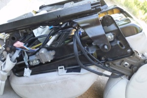 |
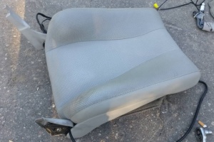 |
Remove/install front seat backrest cover
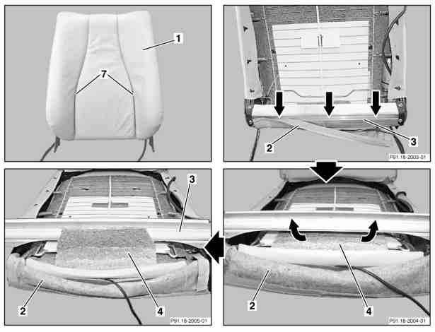
|
|
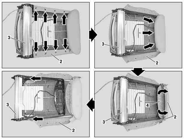
|
|
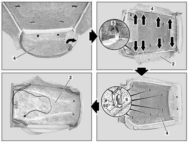
|
|
Remove:
- Remove head restraint guide on front seat
- Remove front seat backrest (1) (up to 31/08/2002). Place front seat backrest (1) with the covering (2) downwards on a suitable base.
- Remove driver's seat cushion (as of 01/09/2002).
- Pull covering (2) out of the insert fold (arrows) on the bottom of the backrest frame (3)
- Pull out shackle of rubberized fiber matting (4) at bottom (arrows) on backrest frame (3)
- Unhook covering (2) all-round at the backrest frame (3) (arrows)
- Disconnect connector for backrest ventilation (with front deluxe seat, incl. heated seat and seat ventilation, code 401a).
- Remove covering (2) with rubberized fiber matting (4) from the backrest frame (3)
- Remove side stapling clips (5) from the stapling wires (7)
- Release stapling clips (6), to do so rotate staple clip through 90° using flat pliers
- Pull the Velcro fabric strips off the rubberized fiber matting (4)
- Pull covering (2) off the rubberized fiber matting (4) and remove
Install:
- Insert stapling clips (6) into rubberized fiber matting (4) and straighten out
- Pull covering (2) at the top over the "head" of the rubberized fiber matting (4)
- Fold upholstery (2) to side, place on rubberized fiber matting (4) and straighten out. When replacing, draw the stapling wires (7) into the fabric sleeves in the covering (2).
- Connect longitudinal stapling wires with the stapling clips (6)
- Align covering (2) with the rubberized fiber matting (4) and fix in position at the side with Velcro fabric strips
- Hook side stapling clips (5) into the stapling wires (7)
- Insert backrest frame (3) into rubberized fiber matting (4)
- Slide shackle of rubberized fiber matting (4) (arrow) at bottom into backrest frame (3)
- Insert covering (2) all way round on backrest frame (3) and at "header piece"
- Install head restraint guide on the front seat
- Install front seat backrest (up to 31/08/2002).
- Install driver seat cushion (as of 01/09/2002).
Remove/install front seat cushion (up to 31/08/2002)
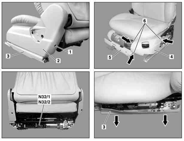
|
|
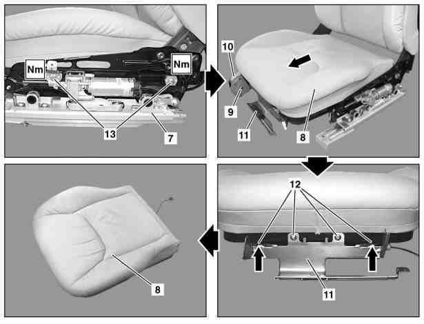
|
|
- Remove front seat
- Remove screw (1) and remove paneling (2)
- Open cap (5) and remove fire extinguisher (with fire extinguisher, code 682).
- Remove screws (6, arrows) and remove paneling (4) and cap (5)
- Pull off paneling (3) in direction of arrow. Ensure that retaining lugs are not damaged.
- Disconnect connector from seat cushion heater on left front seat adjustment control unit with memory (N32/1) and right front seat adjustment control unit with memory (N32/2).
- Remove multicontour backrest control unit from front seat (with driver seat multicontour backrest, code 404b, passenger seat, code 405b).
- Remove screw (9) and remove paneling (10)
- Remove screws (13) and remove seat cushion (8) forwards from the seat adjustment mechanism
- Remove screws (12, arrows) from the seat cushion (8) and remove bracket (11) from the seat cushion (8)
- Install in the reverse order
Torque specifications:
- Bolt, seat cushion to seat adjustment mechanism: 15 Nm (up to 30/11/2001 and as of 01/12/2001)
Remove/install front seat cushion (as of 01/09/2002)
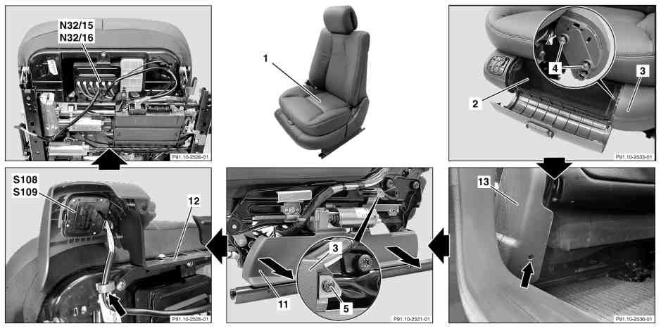
|
|
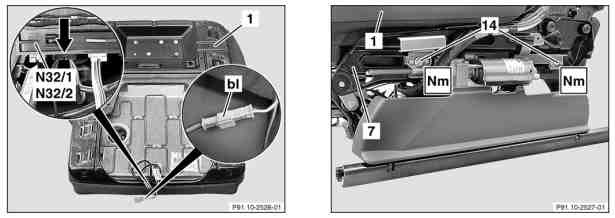
|
|
- Remove front seat. Move seat cushion all the way up and to center position so that rear bolt (14) on belt buckle is accessible.
- Open flap in stowage compartment (2)
- Unclip stowage compartment (2)
- Remove fire extinguisher (with fire extinguisher, code 682).
- Unscrew bolts (4, 2 each) from left side paneling (3)
- Unscrew bolt (see arrow) at rear of paneling (13) on belt end fitting and remove
- Unscrew bolt (5) from left side paneling (3)
- Remove left side paneling (3) in direction of travel
- Unclip bottom side paneling (11) in direction of arrow (with driver seat multicontour backrest, code 404b, passenger seat, code 405b).
- Remove pneumatic lines from lumbar support control valve
- Remove connector coupling from left front multicontour backrest switch group (S109), right front multicontour backrest switch group (S108) (on driver seat multicontour backrest code 404b, passenger seat code 405b or left dynamic seat including multicontour seat code 433, right code 434).
- Remove omega clip (see arrow) from seat cushion frame
- Remove connector coupling from dynamic seat switch (on left dynamic seat incl. multicontour seat code 433, right code 434).
- Remove multicontour backrest control unit from front seat (with driver seat multicontour backrest, code 404b, passenger seat, code 405b).
- Unscrew stowage compartment retaining frame (12) from cushion frame
- Unscrew bolt (14, 2 each) and slide seat cushion (1) on seat adjustment mechanism (7) toward front. Do not yet remove seat cushion (1) from seat adjustment mechanism.
- Disconnect blue connector on fan motor (bl) (for code (401a) front comfort seat, incl. seat heating and seat ventilation).
- Remove coupling for seat cushion heater (see arrow in magnifying glass) from left front seat adjustment control unit with memory (N32/1), right front seat adjustment control unit with memory (N32/2) (for front comfort seats, incl. seat heating and seat ventilation vehicles, code 401a or right and left front seat heaters or code 873).
- Remove seat cushion (1) from seat adjustment mechanism (7)
- Install in the reverse order
- Check seat adjustment for proper function
Torque specifications:
- Bolt, seat cushion to seat adjustment mechanism: 15 Nm
Seat cushion frame is interchangeable between left and right seat cushion. The cushion rest and cushion leather cover, however, have different part numbers in EPC depending on the side. Passenger seat cushion has passenger occupancy sensor installed with extra connector (yellow).
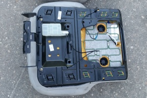 |
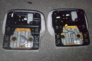 |
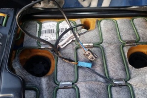 |
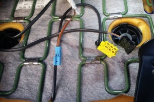 |
Remove/install front seat cushion covering (up to 31/08/2002)
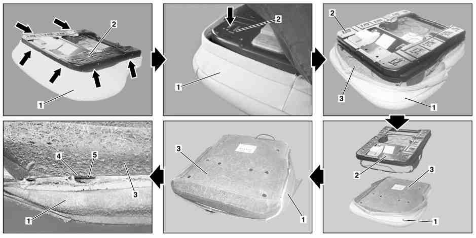
|
|
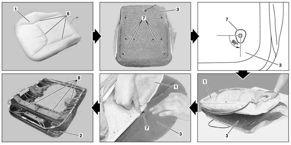
|
|
Remove:
- Remove driver's seat cushion. Place driver's seat cushion on suitable surface with upholstery (1) facing downwards.
- Unclip upholstery all way round (1) from clip groove (arrows) in cushion frame (2). Relieve strain on upholstery (1) by pushing down the cushion frame.
- Remove cushion frame (2) from the rubberized fiber matting (3)
- Remove side upholstery clips (4) from stitching wires (5). Pull upholstery (1) over outer edge of rubberized fiber matting (3).
- Remove upholstery clips (7, 8 pcs.) from stitching wires (6). Do this by rotating upholstery clips (7) 90° using flat nose pliers.
- Remove upholstery (1) from rubberized fiber matting (3).
- Pull stitching wires (5, 6) from upholstery (1). Only when replacing upholstery (1).
Intall:
- Slide stitching wires (5) and (6) into material sleeves on upholstery (1) and straighten out. Only when fitting new upholstery (1).
- Press in upholstery clips (7, 8 pcs.) into rear of rubberized fiber matting (3) and straighten out
- Fold upholstery (1) to side, place on rubberized fiber matting (3) and straighten out
- Use press-in tool to insert stitching wires (6) into upholstery clips (7) Installation tool for stitching wire
- Insert lateral stapling clips (4) into stitching wires (5). Pull upholstery (1) over outer edge of rubberized fiber matting (3) at side and front.
- Insert cushion frame (2) into rubberized fiber matting (3). With foam rubber wedges (8, 4 pcs.) inserted into cushion frame (2).
- Insert upholstery (1) all way round into clip groove. Relieve strain on upholstery (1) by pushing down the cushion frame. Note retaining clamps.
- Install driver's seat cushion
Remove/install front seat cushion covering (as of 01/09/2002)
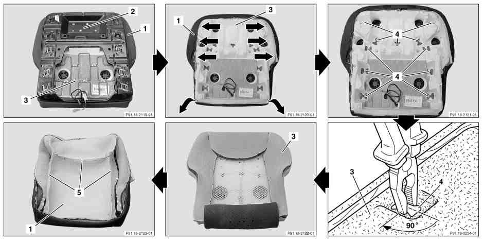
|
|
- Remove driver's seat cushion. Place driver's seat cushion on suitable surface with upholstery (1) facing downwards.
- Unhook covering (1) from clip groove around cushion frame (2). Relieve seat cushion cover (1) tension by pressing cushion frame (2) down.
- Remove cushion frame (2) from foam rubber padding (3)
- Unhook three stapling clips (see arrows) from foam rubber padding (3) at each side. Pull upholstery (1) over outer edge of foam rubber padding (3).
- Remove stapling clips (4, 11 pcs.) from stitching wires (5). Do this by rotating stapling clips (4) 90° using flat nose pliers. Installation: Use push-in tool.
- Remove upholstery (1) from foam rubber padding (3). Installation: Align upholstery (1) on foam rubber padding (3).
- Pull stitching wire (5) out of material sleeves on upholstery (1). Only when replacing upholstery (1).
- Install in the reverse order
Remove/install front seat multicontour backrest control module (code 404b/405b)
|
- Remove front seat
- Unscrew screw (2) and remove frame (3)
- Remove multicontour backrest, front left (N32/15) or right (N32/16)
- Expose control module connecting cable (6) and disconnect from front seat adjustment control module (see arrow)
- Expose switch group connecting cable (7) and disconnect from multicontour backrest switch group
- Open catch (5) and remove pneumatic line connecting rail (1). Open catch (5) using small screwdriver (see arrow).
- Unclip black pneumatic line with diam. of 4 mm (sw) to overpressure reservoir (4) (only if seat cushion or backrest has to be removed).
- Install in the reverse order
- Check multicontour seat backrest for proper function
Remove/install front seat control module (up to 30/06/2001)
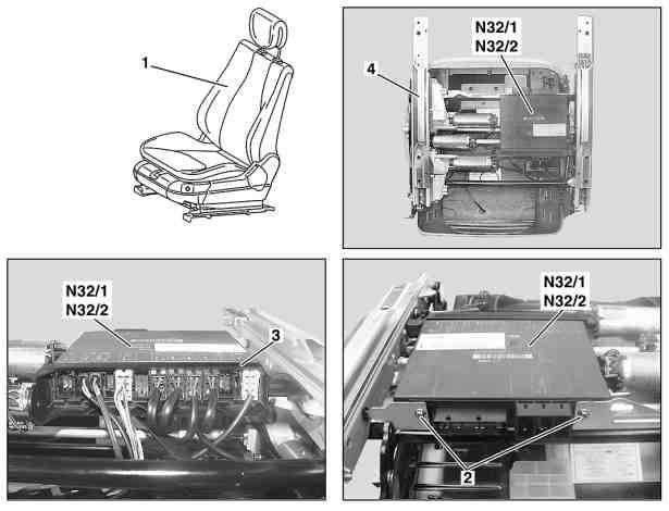
|
|
- Remove front seat (1)
- Disconnect all electrical connectors (3)
- Unscrew internal Torx bolts (2)
- Remove left front seat adjustment control module with memory (N32/1), right (N32/2) from bracket in seat adjuster (4)
- Install in the reverse order
- Perform function check on electric seat adjustment
Remove/install front seat control module (as of 01/07/2001)
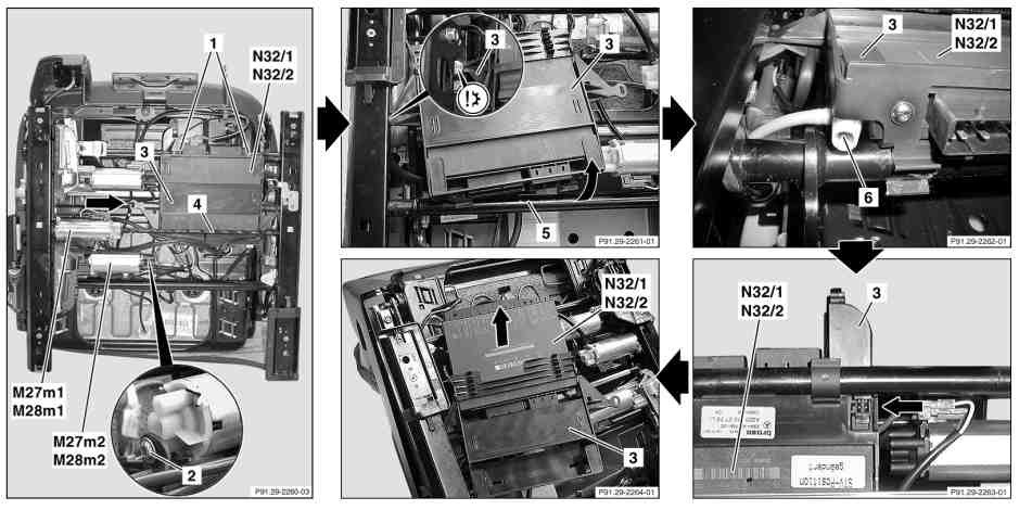
|
|
- Remove front seat
- Remove all connectors to front and rear side of left (N32/1) and right (N32/2) front seat adjustment control module with memory
- Slacken tie straps (see arrow) at control module bracket lug (3). Installation: Use new tie straps.
- Unscrew bolt (1, 2 pcs.) at front of left (N32/1) and right (N32/2) front seat adjustment control module with memory
- Unscrew bolt (2, see magnification) from rear up/down motor (M27m2, M28m2)
- Detach flexible shaft (4) from forward/back motor (M27m1, M28m1)
- Carefully release front control module bracket (3) from transverse rod (5), (see arrow) until both plastic retaining clamps on underside of control module bracket (3) have been unclipped. Control module bracket (3) is fixed to the seat frame with a rivet (see magnification).
- Unclip pneumatic line (6) at front left (N32/1) and right (N32/2) side of left front seat adjustment control module with memory
- Unclip left (N32/1) and right (N32/2) front seat adjustment control module with memory from control module bracket (3) latching lug (see arrow) at front right side
- Push left (N32/1) and right (N32/2) front seat adjustment control module with memory from control module bracket (3)
- Install in the reverse order
- Perform front seat adjustment function test
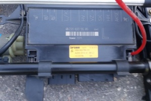
Remove/install front seat adjustment mechanism
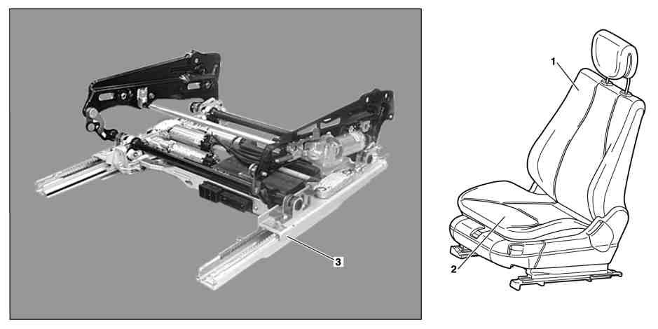
|
|
- Remove front seat backrest (1)
- Remove driver's seat cushion (2)
- Remove front seat control module
- Remove front seat adjustment motor group (seat cushion) - up to 30/06/2001.
- Remove front seat adjustment motor group (seat cushion) (only for front and rear seat cushion and front seat forward and backward) - as of 01.07.2001.
- Remove front seat adjustment motor group (seat cushion) (only for seat cushion forward and backward) - as of 01/07/2001 and up to 31/08/2002, as of 01/09/2002.
- Install in the reverse order
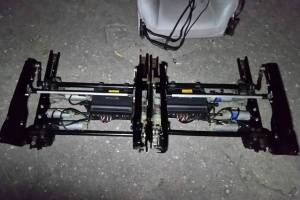 |
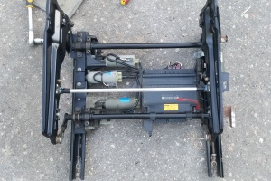 |
Remove/install front seat adjusting motors (up to 30/06/2001)
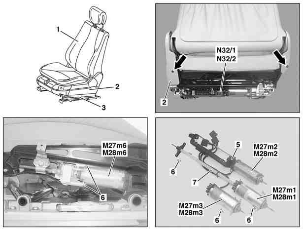
|
|
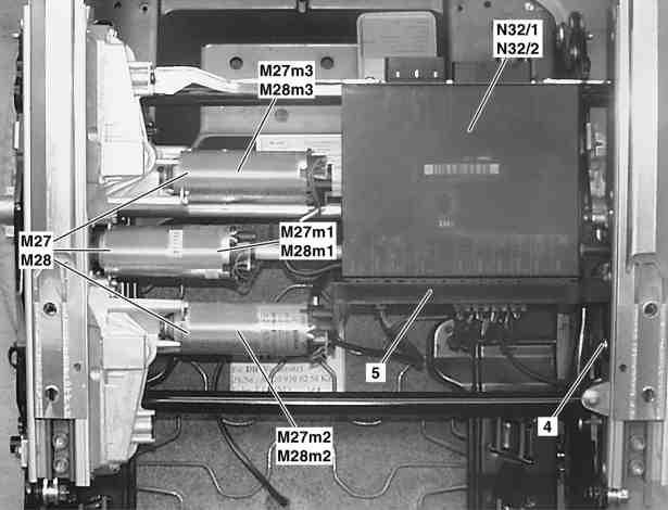
|
|
- Remove front seat (1)
- Undo screws (arrows) on side paneling (2)
- Remove side paneling (2) and (3) from front seat (1)
- Undo bolts (6) on seat cushion fore/aft motor (M27m6) and (M28m6) and remove motor
- Remove left front seat adjustment control unit with memory (N32/1), right front seat adjustment control unit with memory (N32/2)
- Undo bolt (4) from the bracket (5) for the left front seat adjustment control unit with memory (N32/1), right front seat adjustment control unit with memory (N32/2)
- Remove fore/aft motor (M27m1) and (M28m1). Remove screws (6).
- Remove rear up/down motor (M27m2) and (M28m2). Remove screws (6).
- Remove front up/down motor (M27m3) and (M28m3). Remove screws (6).
- Exchange coupling assignment on seat adjustment of fore/aft motors (M27m1) and (M28m1) (only for models 220.0/1 up to chassis end number 189590, when installing new fore/aft motors (M27m1) and (M28m1)).
- Undo bracket (5) for left front seat adjustment control unit with memory (N32/1), right front seat adjustment control unit with memory (N32/2) and the strut (7) of the motor group
- Install in the reverse order
- Check seat adjustment for proper function
Torque specifications:
- Bolt of seat adjustment motor: 4 Nm
Exchange coupling assignment on seat adjustment
- Detach coupling (arrow) on connector assignment.
- Using a suitable tool, slide contact retainer (1) in direction of arrow out of locked position.
- Insert unlocking tool into coupling of contact cavity 5 and remove female contact from coupling by pulling lightly on cable.
- Insert unlocking tool into coupling of contact cavity 6 and remove female contact from coupling by pulling lightly on cable.
- Exchange the female contact from contact cavity 6 with the female contact from contact cavity 5.
- During installation pull lightly on the cables in contact cavities 5 and 6 to check that the female contacts have engaged properly into the housing.
Remove/install front seat (frame forward/back, cushion forward/back, up/down) adjusting motors (as of 01/07/2001)
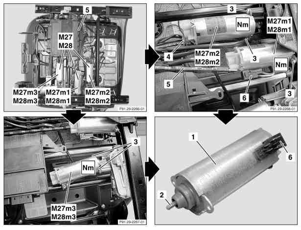
|
|
- Remove front seat (1)
- Unscrew screw (3, 2 pcs.) from front up/down motor (M27m3, M28m3). Only when replacing front up/down motor (M27m3, M28m3).
- Lift front up/down motor (M27m3, M28m3) slightly from transmission, kink over flexible shaft (2) and remove. Only when replacing front up/down motor (M27m3, M28m3).
- Detach seat adjustment shaft (5) from forward/back motor (M27m1, M28m1). Only when replacing forward/back motor (M27m1/M28m1).
- Unscrew screws (3, 2 pcs.) from forward/back motor (M27m1, M28m1). Only when replacing forward/back motor (M27m1/M28m1).
- Detach forward/back motor (M27m1, M28m1) from transmission. Only when replacing forward/back motor (M27m1/M28m1). Flexible shaft (2) remains in transmission.
- Unscrew screw (4) from control module bracket. Only when replacing rear up/down motor (M27m3, M28m3).
- Unscrew screw (3, 2 pcs.) from rear up/down motor (M27m2, M28m2). Only when replacing rear up/down motor (M27m3, M28m3).
- Remove rear raise/lower motor (M27m2/M28m2) from transmission. Only when replacing rear up/down motor (M27m3, M28m3).
- Detach electrical plug (6) from motor (1). Installation: Slide flexible shaft (2) into motor (1) as far as it will go.
- Install in the reverse order
- Perform function check of respective electric seat adjuster
Torque specification:
- Bolt of seat adjustment motor: 4 Nm
Remove/install front seat (seat cushion forward/back) adjusting motors (as of 01/07/2001 up to 31/08/2002)
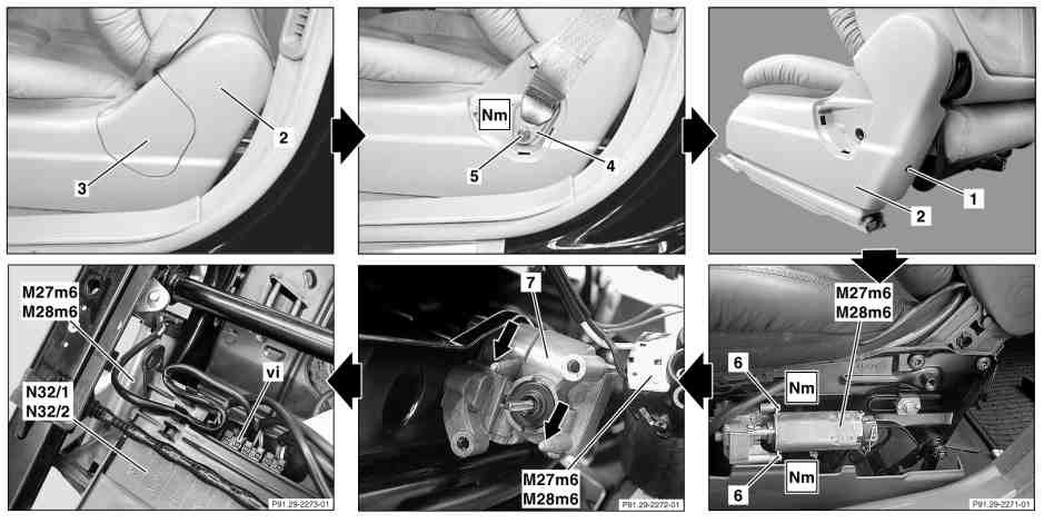
|
|
- Move front seats toward front. Move front and back seat cushions up as far as possible.
- Remove cover (3) from side trim (2)
- Unscrew screw (5) from belt end fitting (4). Installation: When screwing on, please ensure that the belt end fitting (4) remains mobile.
- Unscrew bolt (1) and unclip and remove upper trim (2)
- Unscrew screws (6, 2 screws) from seat cushion forward/back motor (M27m6, M28m6)
- Remove seat cushion forward/back motor (M27m6, M28m6) from transmission (7). Shaft remains in transmission (7). Installation: Motor must be inserted into pilot stud (arrows).
- Unclip connecting cable to underside of left (N32/1) and right (N32/2) front seat adjustment control unit with memory. Installation: Carefully clip connecting cable into retaining clamps on underside of control unit.
- Unplug violet coupling (vi) from left (N32/1) and right (N32/2) front seat adjustment control unit with memory
- Remove seat cushion forward/back motor (M27m6, M28m6) with connecting cable
- Install in the reverse order
- Check seat adjustment for proper function
Torque specification:
- Bolt of seat adjustment motor: 4 Nm
- Screw/nut on front seat belt buckle: 30 Nm
Remove/install front seat (seat cushion forward/back) adjusting motors (as of 01/09/2002)
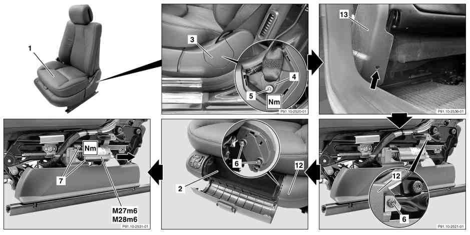
|
|
- Adjust front seat (1) to front. Move front and back seat cushions up as far as possible.
- Remove cover (3) from rear side trim (13)
- Unscrew screw (5) from belt end fitting (4). Installation: When screwing on, please ensure that the belt end fitting (4) remains mobile.
- Remove screw (see arrow) from rear side trim (13)
- Unscrew screw (6, see magnification) from left side trim (12)
- Open stowage compartment flap (2)
- Unclip and remove stowage compartment (2)
- Remove fire extinguisher (for vehicles with fire extinguisher code 682)
- Unscrew screws (6, 2 screws) from left side trim (12)
- Pull off left side trim (12) in direction of travel
- Unscrew screw (7, 2 screws) from seat cushion forward/back motor (M27m6, M28m6)
- Remove seat cushion forward/back motor (M27m6, M28m6) from transmission. Shaft remains in transmission.
- Unplug connector from seat cushion forward/back motor (M27m6, M28m6)
- Install in the reverse order
- Perform function check of seat cushion forward/back facility
Torque specification:
- Bolt of seat adjustment motor: 4 Nm
- Screw/nut on front seat belt buckle: 30 Nm
Remove/install front seat (backrest and head restraint) adjusting motors
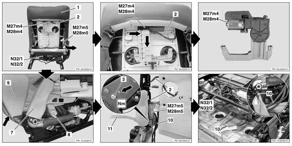
|
|
- Remove front seat
- Remove seat-back lining from seat backrest
- Remove head restraint up/down motor (M27m4/M28m4). Only when replacing. First press head restraint up/down motor (M27m4/M28m4) to right side and then remove downward.
- Expose upholstery (1) around backrest forward/back motor (M27m5, M28m5) (see arrow)
- Remove side paneling (9) from seat belt buckle (7). Screws (8, arrow) and retaining clip (see detail).
- Disconnect head restraint wiring harness (2) from head restraint up/down motor (M27m4, M28m4). Head restraint wiring harness (2) and wiring harness (10) are connected together with the backrest forward/back motor (M27m5, M28m5).
- Expose head restraint wiring harness (2) at right side of backrest frame
- Expose wiring harness (1) of left (N32/1), right (N32/2) front seat adjustment control module with memory as far as backrest forward/back motor (M27m5, M28m5). Installation: Fix wiring harness (10) to existing cables using tie straps.
- Unscrew screw (3) from right backrest frame and pull backrest forward/back motor (M27m5, M28m5) out towards rear
- Install in the reverse order
- Check seat adjustment for proper function
Torque specifications:
- Bolt, backrest adjustment motor: 5 Nm
Remove/install front seat blower regulator for seat ventilation motors (code 401)
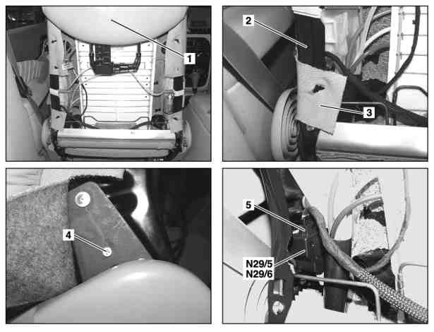
|
|
- Remove tensioning element (front seat backrest seat-back lining) from front seat backrest (1)
- Detach backrest upholstery (3) from backrest frame (2)
- Disconnect connector (5) from left (N29/5) and right (N29/6) front seat ventilators
- Unscrew bolt (4) and remove left (N29/5) and right (N29/6) front seat ventilator blower regulator
- Install in the reverse order
- Perform seat ventilation function test
Remove/install front seat cushion ventilation motors (code 401)
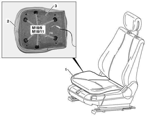
|
|
- Remove driver's seat cushion (1)
- Remove cover of front seat cushion
- Remove defective front left (M18/9) and right (M18/11) seat cushion ventilation motor group together with rubberized fiber matting/foam rubber (3). Individual motors are not replaced - the entire motor group with rubberized fiber matting/foam rubber (3) is replaced.
- Install in the reverse order
- Perform seat ventilation function check
Remove/install front seat backrest ventilation motors
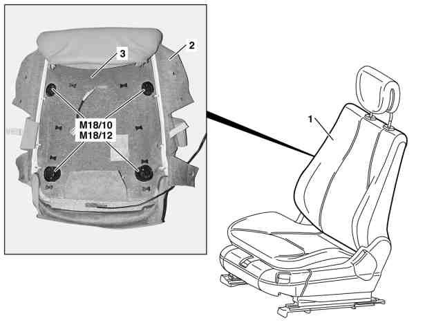
|
|
- Remove covering on front seat backrest
- Remove defective front left (M18/10) and right (M18/12) seat backrest ventilation motor group together with rubberized fiber matting (3). Individual motors are not replaced - the entire motor group with rubberized fiber matting (3) is replaced.
- Install in the reverse order
- Perform seat ventilation function check
Remove/install front seat multicontour backrest control switch (code 404/405) (up to 31/08/2002)
|
- Unclip front right (S108), left (S109) multicontour backrest switch group out of front seat paneling (1) with assembly wedge (2)
- Disconnect electrical connector
- Install in the reverse order
- Perform multicontour backrest function check
Remove/install front seat multicontour backrest control switch (code 404/405) (as of 01/09/2002)
|
- Drive front seat backwards. Move seat cushion upwards as far as possible.
- Push front right (S108), left (S109) multicontour backrest switch group out of cover (2). Move hand beneath cover (2) and push switch group out.
- Detach electrical connecting cable. Omega clip may need to be removed from seat cushion frame (see arrow).
- Install in the reverse order
- Perform function test of front right (S108), left (S109) multicontour backrest switch group
Remove/install multicontour backrest center air cushion (code 404/405)
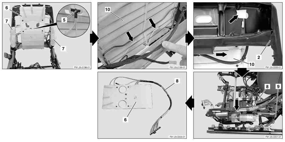
|
|
- Remove driver's seat cushion
- Remove covering on front seat backrest. Only remove backrest covering with rubberized fiber matting from backrest frame
- Pull off all pneumatic line from the T-piece (5, see enlarged section) on the back of the center air cushion (6)
- Pull all pneumatic lines out of the tongues on the back of the center air cushion (6)
- Pull strip of adhesive tape on the top part of the center air cushion (6) off the backrest frame. Installation: Fasten the upper air cushion of the center air cushion (6) with strip of adhesive tape so that they cannot fold down.
- Unfold lower tongues (see arrows) of the reinforcement plate (10) downwards out of the backrest frame. Installation: Secure tongues after turning around on grid.
- Press out the corners (see arrow, top) of the reinforcement plate (10) on the right and left next to the head restraint guides. Do not damage the corners of the reinforcement plate (10). Installation: The upper retainer tabs (see arrow, bottom) of the reinforcement plate (10) must be guided into the second grid brace from above.
- Detach pneumatic lines (8) from seat frame (9) and re-convert up to the center air cushion (6). Ensure that it cannot chafe. Installation: Fasten the pneumatic lines (8) to the seat frame (9) with a tie strap (see arrow).
- Pull center air cushion (6) upwards off the backrest frame
- Install in the reverse order
- Carry out function check of multicontour backrest
Remove/install multicontour backrest side air cushions (code 404/405)
|
- Remove driver's seat cushion
- Remove covering on front seat backrest. Only remove backrest upholstery with rubberized fiber matting from front seat backrest.
- Detach pneumatic line for side air cushion (7) from T-piece (5) at rear of center air cushion (see magnifying glass)
- Pull pneumatic line out of tab on rear of center air cushion
- Undo both tensioning straps (11) around side air cushion (7) from backrest frame (2)
- Unscrew screw (10) from backrest frame (2)
- Push bracket (12) with side air cushion (7) upwards and remove
- Slacken retaining straps (11) on bracket (12)
- Pull side air cushion (7) from bracket (12) and remove
- Install in the reverse order
- Perform multicontour backrest function check
Remove/install front seat backrest frame overpressure reservoir
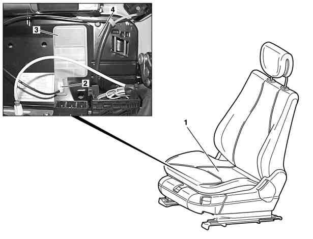
|
|
- Remove front seat (1)
- Removing multicontour backrest control module from front seat (with driver seat multicontour backrest code 404b, passenger seat code 405b).
- Detach pneumatic connecting line (2) from overpressure reservoir (3)
- Push overpressure reservoir (3) from cushion frame (4) using assembly wedge. Installation: When installing the overpressure reservoir (3), ensure that the retaining clamp engages in the hole in the cushion frame.
- Install in the reverse order
- Perform function check of lumbar support or multicontour backrest
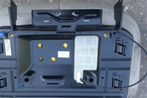
Remove/install front seat backrest lumbar support air cushion (except code 404/405/433/434)
Shown on vehicle without front luxury seat, incl. heated seat and seat ventilation, code 401a:
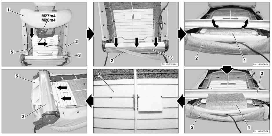
|
|
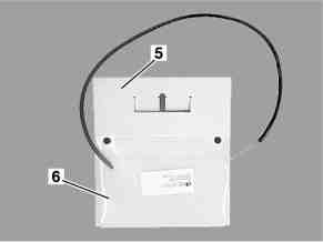
|
|
- Remove front seat backrest (1)
- Remove tensioning element (seat backrest seat-back lining) from front seat backrest
- Remove head restraint raise/lower motor (M27m4/M28m4). Push motor to right first and then remove downwards.
- Place front seat backrest (1) onto a suitable underlay with the backrest cover (2) facing downwards
- Pull backrest upholstery (2) out of clip groove (arrows) at bottom of backrest frame (3)
- Pull out rubberized fiber matting (4) lug (arrows) at bottom of backrest frame (3)
- Detach lugs on reinforcement plate (5) from spring wire of backrest frame (3). Do not damage lugs.
- Pull reinforcement plate (5) with air cushion (6) out of backrest frame (3). Lift backrest frame (3) with spring wire from backrest upholstery (2) with rubberized fiber matting (4).
- Install in the reverse order
- Perform lumbar support function check
Remove/install front seat backrest lumbar support control valve
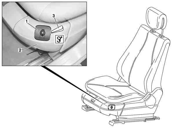
|
|
With model refinement 2003 (as of 01/09/2002) the position of the control valve (1) has been changed to the inboard side of the seat.
- Unclip control valve (1) with assembly wedge (3) from front seat paneling (2)
- Detach pneumatic line and disconnect pneumatic connector. Pay attention to line routing.
- Install in the reverse order
- Perform lumbar support function check
Front passenger seat occupied and child seat recognition sensor (B48)
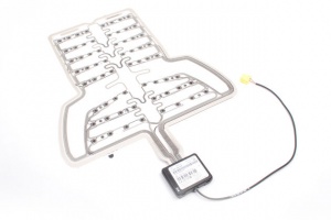 |
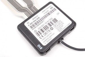 |
If the SRS indicator and warning lamp stays on or comes on intermittently a possible cause is that the passenger seat occupancy sensor (also known as weight sensor or SRS sensor mat) is faulty or failing.
| Error Code | Generated By | Description |
|---|---|---|
| 9028 | AB - Airbag | The coding for component B48 (Front passenger seat occupied and child seat recognition) is faulty. |
There are four options to fix the SRS indicator and warning lamp staying on:
- Replace the front passenger seat occupied and child seat recognition sensor (B48). The sensor costs around EUR 480 and its replacement involves dissecting seat cushion (be warned this is a substantial task). The DAS can be used to test the connection to see if the seat is empty or occupied; it should set off as occupied after 26 lbs" (12Kg).
- Diagnose where the issue is occurring and fix the sensor (see below).
- Disable the passenger seat occupancy sensor in DAS (see section below).
- Replace the sensor with an electronic sensor emulator (see section below).
Fixing seat occupancy sensor
If the Airbag ECU says it can't communicate with the seat occupancy sensor, or open or shorted wiring, then any one of these causes may exist:
- Breakage of electrical cable between the plug connector and the sensor (quite common). If this is the case the wire can be repaired.
- The sensor elements may be dead
- The sensor electronics may be shorted. This can be quickly verified by measuring the voltage between the red and brown wires in the yellow connector, the voltage should be about 12V DC. The sensor mat gets the power from the seat control module located under the passenger seat. If it is around 0.6V, the sensor is short-circuiting the supply voltage to the ground which causes the built-in circuit protection to drop the voltage to 0.6V when the sensor is connected. The electronics are in the white box inside the seat cushion. The white box is filled with some caulk type filler. Nasty job, this box is neither meant to be opened nor repaired. Once opened and the caulk excavated (using knives, screw drivers and a heat gun) to reveal the components, there can be found a 15uF tantalum capacitor which is shorted when voltage is applied to it. It can be replaced with a regular electrolytic capacitor.
Disabling seat occupancy sensor in DAS
To disable passenger seat occupancy sensor in DAS select control unit "AB - Airbag" -> "Development data" -> "Control unit adaptations" -> "Control unit adaptations (Variant coding)" -> "Fahrzeugausstattung kodieren" and change "AKSE/OC Beifahrer" from "ja" to "nein" (see photo below).
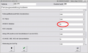
In case "AB - Airbag" control unit has been reset, the "Initial startup" will reset the module to default settings enabling the passenger seat occupancy sensor. If seat occupancy sensor will throw error codes the "Initial startup" will complete only partially showing "Initial startup could only be partially completed. Cause: - There are current fault codes present.". The "Initial startup" can be completed fully by locking the control module using "Development data" -> "Actuations" -> "Complete index of actuations" -> "Steuergerät verriegeln (FN_SG_Verriegeln)". This will lock the ECU and SRS light will go off.
Installing seat occupancy sensor emulator
An electronic emulator may be purchased on eBay for a few dollars and substituted for the SRS Sensor Mat. Search for something like "seat occupation sensor emulator W220" (~EUR 10).
There are two types of sensors available depending on W220 model year:
Safety note: The emulator simulates that there is always someone sitting in the passenger seat, so in case of an accident, the airbag goes on. Do not carry babies or children in the front seat, activating the airbag can cause serious damage in the event of a collision.
The emulator is not a simple device but contains several electronic components.
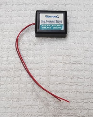 |
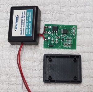 |
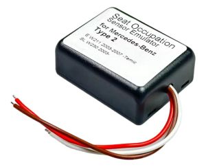 |
Install of the emulator:
- Put the seat fully forward and then lift up the rear section and place on a suitable support to expose the underneath part of the seat.
- Identify the SRS occupancy sensor connector. It is the yellow connector with red, white and brown wires.
- Unplug the SRS occupancy sensor and make the cable accessible. You may have to cut one or two plastic ties to fully release the cable. Then cut the plug off the cable at the point marked with the red arrow.
- The cut-off plug may now be taken to a workbench and the emulator soldered to the plug leads. Observe the correct colors, i.e., red to red (+12V), white to white (data) and brown to brown (Ground). Make sure to place heat shrink sleeving over the emulator wires before connecting them.
- Shrink the protective sleeving and the emulator is now finished.
- Reconnect the SRS occupancy sensor plug to its socket (left red arrow) and secure with plastic tie to the existing bunch of cables (right red arrow).
- Reassemble the passenger seat.
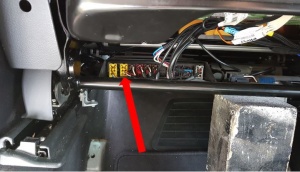 |
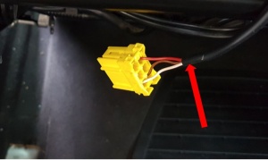 |
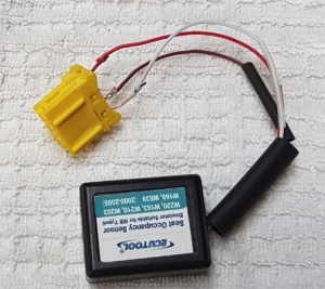 |
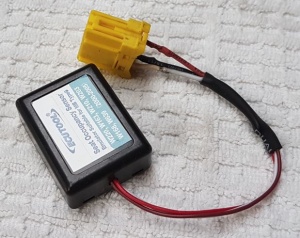 |
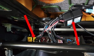 |
Remove/install seat occupied recognition sensor (up to 31/08/2002)
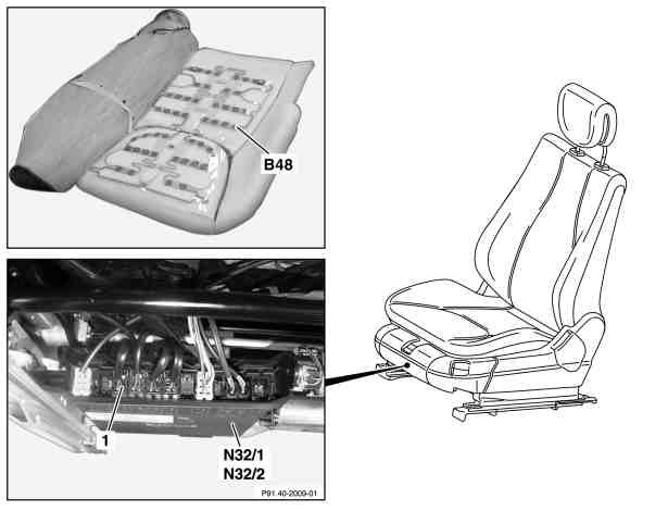
|
|
- Remove cover of front seat cushion. On passenger-side only.
- Switch off ignition, withdraw ignition key
- Switch off engine, remove transmitter key from vehicle (with keyless go code 889). Keep transmitter key outside the transmitter range.
- Guide the connector (1) upwards out of the rubberized fiber matting
- Remove the front passenger seat occupied and child seat recognition sensor (B48) from the rubberized fiber matting. Installation: Lay the front passenger seat occupied and child seat recognition sensor (B48) evenly on the rubberized fiber matting. The woven side must face upwards. Do not kink front passenger seat occupied and child seat recognition sensor (B48).
- Install in the reverse order
- Carry out diagnosis
Remove/install seat occupied recognition sensor (as of 01/09/2002)
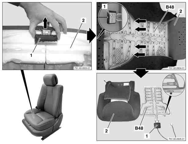
|
|
- Remove cover of front seat cushion. On passenger-side only.
- Pull control module with connection line (1) out of the end face of the foam padding (2) (see arrow). Guide connection line through the slot in the foam padding (2).
- Open foam padding (2) on the seat surface and expose front passenger seat occupied and child seat recognition sensor (B48)
- Pull fastening hooks (see arrows) out of the foam padding (2). Pull out the fastening hooks slowly and carefully so that the foam support (2) is not damaged.
- Pull out the control module with connection line (1) between the core and seat surface of the foam padding (2)
- Remove front passenger seat occupied and child seat recognition sensor (B48) from seating surface of the foam support (2).Installation: It is essential to ensure that the film with the identification "TOP" (see enlarged section) is inserted upwards.
- Install in the reverse order
- Carry out diagnosis
Retrofit front seat height adapter
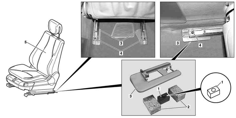
|
|
- Remove bolts (4, 4 pieces) on the front and rear seat rail
- Raise front seat frame, place spacers (1) (part number A2209101736) on the right and left as well as at the front and rear under the under the seat rails and fasten with the bolts contained in the accessories. Do not damage covers (3).
- Clamp foamed material (2) in each case in front of and behind the spacer (1) under the covers (3) of the seat rails
- Check seat adjustment for proper function
- If the package changes, supplement the code or designation of the relevant special equipment on the vehicle data card
Torque specifications:
- Bolt to seat runner: 50 Nm (up to 30/11/2001)
