Overhead Control Panel (OCP) (N70): Difference between revisions
Ricebubbles (talk | contribs) (Rearranged and added new Issue on Failed Air Temperature Sensor (N70/b1)) |
Ricebubbles (talk | contribs) |
||
| (2 intermediate revisions by the same user not shown) | |||
| Line 38: | Line 38: | ||
==DIY Procedures - Overhead Control Panel (OCP) (N70)== | ==DIY Procedures - Overhead Control Panel (OCP) (N70)== | ||
=== | ===Testing - Overhead Control Panel (OCP) (N70)=== | ||
=== | As the testing methods for the Overhead Control Panel (OCP) (N70) are very similar to the testing methods for the Pushbutton Control Module (N22) refer to section [[Pushbutton Control Module (N22)]]. | ||
===Removal - Overhead Control Panel (OCP) (N70)=== | |||
<!-- AR82.20-P-1000M, Removing and installing overhead control panel control module --> | <!-- AR82.20-P-1000M, Removing and installing overhead control panel control module --> | ||
| Line 45: | Line 47: | ||
|[[File:W220_removing_overhead_control_panel_control_module.jpg]] | |[[File:W220_removing_overhead_control_panel_control_module.jpg]] | ||
| | | | ||
* 1 - Light lenses | * 1 - Light lenses | ||
* 2 - Electrical connectors and connections | * 2 - Electrical connectors and connections | ||
* N70 - Overhead control panel control module | * N70 - Overhead control panel control module | ||
|} | |} | ||
# Remove light lenses (1) | # Remove the two light lenses (1) off by prying from the rear. You will then see either two or four steel clips (depending on model) that hold N70 in place. See the yellow arrows in the picture. | ||
# | #: [[File:W220 Overhead Control Panel N70 Mounting Clips.jpg|500px|center]] | ||
# Disconnect electrical connectors (2) and connections (2) | # Pry the steel clips towards the center of the unit and you should be able to pull it down slightly as you work around then fully down when you release the last tab. WIS says to press clips (arrows) in direction of arrow and swing overhead control panel control module (N70) down. | ||
# | #: [[File:W220 Overhead Control Panel N70 Cable Connections.JPG|500px|center]] | ||
#: '''Aspirator Fan Interim Test - Overhead Control Panel (OCP) (N70)''' | |||
#: After you have dropped the console but before you disconnect the wires, just turn the ignition to the on position and with a flashlight you can see the fan spinning in an opening at the end of the unit. | |||
# Disconnect electrical connectors (2) and connections (2). The two largest connectors are locked in place by levers (yellow arrow). Press the tab and move the leavers down and the connection will come out easily. The other wire connectors are friction only. | |||
#: [[File:W220 Overhead Control Panel N70 Cable Connections Partly Removed.JPG|500px|center]] | |||
# Reinstall in opposite order. TIP: Check position and number of cables routed through cable clamp before installing OCP. Photo shows a 2003 Update S500. | |||
[[File:W220 Overhead Control Panel N70 Cable Connections.JPG|600px|center]] | |||
===Dismantle - Overhead Control Panel (OCP) (N70)=== | |||
Once the OCP is on a clean work bench it can be dismatled to access the aspirator fan and the thermistor temperature sensor. | |||
# Remove Light Bulbs. | |||
# Remove Back Cover by removing the nine torx screws. | |||
# Remove Circuit Board by pushing it out of the housing. | |||
# Reinstall in reverse order. | |||
===Repair - Overhead Control Panel (OCP) (N70)=== | |||
[[File:W220 Overhead Control Panel N70 | The OCP has one circuit board that includes lighting control, sunroof control and the inside temperature sensor. The yellow arrow is pointing at the Air Temperature Sensor or Thermistor in the center of the mini fan. | ||
[[File:W220 Overhead Control Panel N70 Thermistor Location on PCB.jpg|500px|center]] | |||
# Inspect Fan Shroud. The fan shroud is just clipped to the fan base and is, by design, a little loose which can cause it to rattle. Not really loose, but you can jiggle it a little bit with almost no force. During reinstallation add four small blobs of silicon adhesive to each corner of the fan shroud to secure it to the pcb. | |||
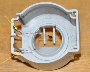
# Inspect the thermistor which is attached by its wires which are melted in place to the fan housing. The thermistor wires are marked with yellow arrows in the photo. They are very brittle and will often be found broken thus causing an issue. The thermistor leads often break due to: | |||
#: * Contact with the fan (they run right up beside it). | |||
#: * Fatigue from micro motion of the fan cover or | |||
#: * Corrosion of the leads or | |||
#: * A combination of the above. | |||
#: [[File:W220 Overhead Control Panel N70 Thermistor Location in Shroud.jpg|300px|center]] | |||
# If the wires are not broken they must be unsoldered before removing the fan shroud (with the thermistor connected inside the shroud). This is very difficult to do and it is much easier to cut the wires half way along the vertical length. The thermistor wires marked with yellow arrows are soldered to the printed circuit board near the base of the fan. | |||
#: [[File:W220 Overhead Control Panel N70 Thermistor Soldering Points.jpg|500px|center]] | |||
# During reassembly thoroughly clean any dust from the aspirator motor and thermistor housing. | |||
==Resistance Specification - Sensor N70/b1 which is in Overhead Control Panel N70== | ==Resistance Specification - Sensor N70/b1 which is in Overhead Control Panel N70== | ||
Latest revision as of 03:32, 16 December 2017
Back to: WIS 83.40 Automatic Climate Control (ACC) or Heating Ventilation and Air Conditioning (HVAC)
Issues - Overhead Control Panel (OCP) (N70)
Failed Air Temperature Sensor (N70/b1) - Overhead Control Panel (OCP) (N70)
The Auto Climate Control (ACC) Air Temperature Sensor (N70/b1) in the Overhead Control Panel (OCP) (N70) often fails and causes the ACC to malfunction. This is easily diagnosed by utilising the ACC Hidden Menu Feature (See Automatic Climate Control (ACC) Service Menus which allows an access/review/read of the ACC actual parameter values during normal operation. Parameter NR.01: In Car Temperature Sensor (N70/b1), ACC Overhead Control Panel (OCP) (N70) should indicate the in cabin air temperature near the roof of the vehicle, eg 27C. If it reads 0C and the cabin is not freezing then there is a fault. The solution is to test the thermistor and aspirator function and then if necessary replace it. As this sensor is very similar to the In Cabin Air Temperature Sensor (N22/b1) in the Pushbutton Control Module (N22) see section Testing - In Cabin Air Temperature Sensor (N22/b1). To replace it see section DIY Procedures - Overhead Control Panel (OCP) (N70) below.
Noisy Aspirator - Overhead Control Panel (OCP) (N70)
Inside the Overhead Control Panel (OCP) (N70) is the aspirator which draws cabin air over a temperature sensor. This signal is used by the Automatic Climate Control (ACC) to condition the cabin space. Note air is also drawn over a temperature sensor in the ACC Pushbutton Cotrol Module also for ACC temperature control.
A common issue is the aspirator housing rattles. The solution is to dismantle the OCP and add small blobs of silicon at the four corners to secure the aspirator shroud to the printed circuit board.
Dirty Sensor and Aspirator - Overhead Control Panel (OCP) (N70)
Often in an attempt to quieten a noisy aspirator owners will spray a silicon based lubricant in through the ventilation slots. DO NOT DO THIS! The aspirator blower is a self lubricated part, so spraying some Silicone or Teflon on it may keep it quiet for a short while but it will allow dust to accumulate and gunk it up to the point of having to replace the part. The solution is to dismantle the OCP and clean the Sensor and Aspirator.
Electrical Connector - Overhead Control Panel (OCP) (N70)
Warning: if attempting DIY repairs be aware that one of the OCP electrical connectors is particularly difficult to reinstall and if not done correctly can be a nightmare to diagnose.
The connector can feel seated when it clicks into place but if not properly seated will give error codes and malfunctions.
Refer to the excellent article by BenzWorld Member jwells at Post #8: http://www.benzworld.org/forums/w220-s-class/1460424-need-help-c-diag.html
The Issue
If you remove the OCP and remove the four or five electrical plugs (depending on model), then reinstall the electrical plugs, you need to pay special attention to the second plug in from the left. It is the one with a light gray swing clip on it that you pull to the left to cause the plug to slide itself out. When plugging it back in, if you just plug it in and move the lever back to the right, it will not seat itself all the way back in.
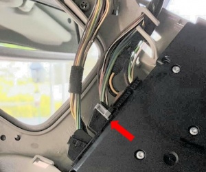
It might look and feel like it is connected, but often it is not.
You will receive an error or malfunction warning saying "Light Sensor Visit Workshop", and it will cause three issues:
- The headlights will stay on when in AUTO mode on the light switch, no matter if it is day or night.
- The automatic headlight delayed shut off will not work in Auto mode, the lights just turn off when you turn off the key instead of having a delayed turn off.
- The Rain Sensing wipers will not work in the first click position, they just act as intermittent wipers wiping every five seconds no matter how much rain is sensed.
The Solution
You MUST push in that second plug until it clicks in, then pull the lever back to the right to lock it in place. You will see on the black part of the plug a half circle tract that the light gray clip follows. The left side of that half circle must be right up against the module you are plugging into.
DIY Procedures - Overhead Control Panel (OCP) (N70)
Testing - Overhead Control Panel (OCP) (N70)
As the testing methods for the Overhead Control Panel (OCP) (N70) are very similar to the testing methods for the Pushbutton Control Module (N22) refer to section Pushbutton Control Module (N22).
Removal - Overhead Control Panel (OCP) (N70)
|
|
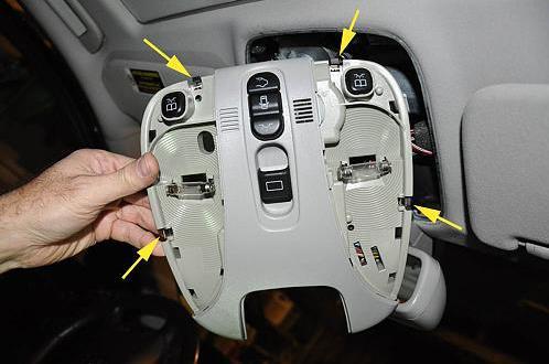
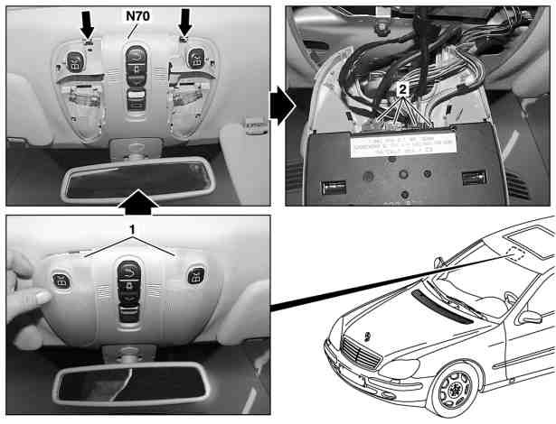
- Remove the two light lenses (1) off by prying from the rear. You will then see either two or four steel clips (depending on model) that hold N70 in place. See the yellow arrows in the picture.
- Pry the steel clips towards the center of the unit and you should be able to pull it down slightly as you work around then fully down when you release the last tab. WIS says to press clips (arrows) in direction of arrow and swing overhead control panel control module (N70) down.
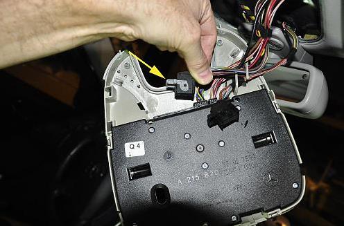
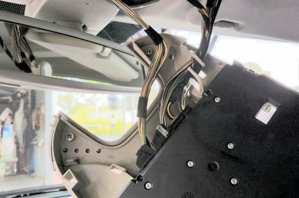
- Disconnect electrical connectors (2) and connections (2). The two largest connectors are locked in place by levers (yellow arrow). Press the tab and move the leavers down and the connection will come out easily. The other wire connectors are friction only.
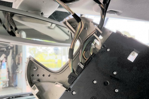
- Reinstall in opposite order. TIP: Check position and number of cables routed through cable clamp before installing OCP. Photo shows a 2003 Update S500.
Dismantle - Overhead Control Panel (OCP) (N70)
Once the OCP is on a clean work bench it can be dismatled to access the aspirator fan and the thermistor temperature sensor.
- Remove Light Bulbs.
- Remove Back Cover by removing the nine torx screws.
- Remove Circuit Board by pushing it out of the housing.
- Reinstall in reverse order.
Repair - Overhead Control Panel (OCP) (N70)
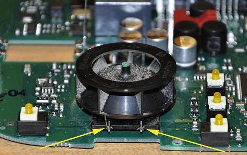
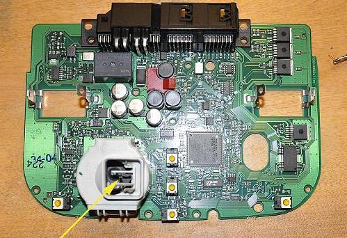
The OCP has one circuit board that includes lighting control, sunroof control and the inside temperature sensor. The yellow arrow is pointing at the Air Temperature Sensor or Thermistor in the center of the mini fan.
- Inspect Fan Shroud. The fan shroud is just clipped to the fan base and is, by design, a little loose which can cause it to rattle. Not really loose, but you can jiggle it a little bit with almost no force. During reinstallation add four small blobs of silicon adhesive to each corner of the fan shroud to secure it to the pcb.
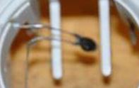
- Inspect the thermistor which is attached by its wires which are melted in place to the fan housing. The thermistor wires are marked with yellow arrows in the photo. They are very brittle and will often be found broken thus causing an issue. The thermistor leads often break due to:
- If the wires are not broken they must be unsoldered before removing the fan shroud (with the thermistor connected inside the shroud). This is very difficult to do and it is much easier to cut the wires half way along the vertical length. The thermistor wires marked with yellow arrows are soldered to the printed circuit board near the base of the fan.
- During reassembly thoroughly clean any dust from the aspirator motor and thermistor housing.
Resistance Specification - Sensor N70/b1 which is in Overhead Control Panel N70
Refer to section Resistance Specification - In Cabin Air Temperature Sensor which applies to both In Cabin Air Temperature Sensors ie Sensor N22/b1 which is in Pushbutton Control Module (N22) and Sensor N70/b1 which is in Overhead Control Panel N70. The OEM sensors were found to be not identical in appearance although their electrical properties were very similar.
- Sensor N70/b1 which is in Overhead Control Panel N70,
