Engine mounts: Difference between revisions
Ricebubbles (talk | contribs) (→DIY Replace - Engine Mount Front: Added link to axtra method for engine mount replacement.) |
(→Replacement of front engine mounts (alternative method): instructions and photos for V6 (S350) engine.) |
||
| (31 intermediate revisions by 3 users not shown) | |||
| Line 1: | Line 1: | ||
== Engine mounts== | |||
[[File:W220_engine_mounts_location.jpg|600px]] | |||
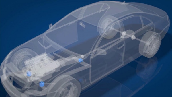
An engine mount is the part that holds the engine in your car. In W220 the engine and transmission are bolted together and held in place by three mounts. There are two engine mounts in the front and one on the rear holding transmission (also called the transmission mount). | |||
One part of the engine mount is bolted to the car body or frame. Another part holds the engine. An engine is a source of vibration, as it has many moving and rotating parts. The job of an engine mount is not only to hold the engine in place, but to reduce the engine vibration felt inside the car. | |||
Engine mounts are made with a rubber material so that there is no direct metal-to-metal contact between the engine and the car body. | |||
To further dampen the vibration, front engine mounts are filled with liquid. A liquid-filled engine mount works like a shock absorber. | |||
An engine mount doesn't need any maintenance or regular servicing. It only needs to be replaced when it fails or wears out. | |||
== | The most common problem with the engine mount is when the rubber part breaks or separates or when liquid starts leaking out of the liquid-filled mount. | ||
=== | Common symptoms of a failed engine mount is the increase in engine noise and vibration felt inside the car. | ||
* WIS specifies removing | Often, the excessive vibration is more noticeable at idle with the transmission engaged. | ||
engine block. This worked fine on the RIGHT mount, but on the LEFT, a hose prevented taking the mount out/or installing, in one piece. This required a combination "Bottom-Side" and "Top-Side" approach. | |||
== How a failed engine mount is diagnosed == | |||
Visible signs of a failed engine mount include cracks, tears and separation in the rubber, as well as leaking liquid. See the photos above. A worn-out engine mount may appear sagging. | |||
Before a bad engine mount is confirmed, all other causes must be eliminated. For example, when one of the exhaust pipe hangers is broken, it may create the same symptoms as a bad engine mount. | |||
When a bent or damaged exhaust pipe touches one of the chassis components, it also creates vibration and rattling noise when shifted to Drive or Reverse noticeable inside the car. | |||
Often, when one of the mounts is bad, an engine may appear seating lower on the side of the bad mount. | |||
Often when one engine mount goes bad, it adds more strain on all other mounts. For this reason, it's not uncommon to see two mounts that need replacement at the same time. | |||
Many Mercedes-Benz owners experience vibrations through the interior of the car, the steering wheel and the seat which is the first sign that your engine mounts are failing or have failed. Sometimes a very common "shaking at idle" issue can be solved by replacing the engine mounts. | |||
Other Mercedes-Benz owners have reported having a smooth idle until you put the car into gear, then a vibration is noticed. | |||
Below is an example of new and old W220 engine mounts (V12 engine). Notice how the old mount has collapsed by about one third its height. | |||
The other picture shows a complete split in two with zero hydraulic fluid remaining after 143,000 miles (230,000Km). | |||
{| | |||
|[[File:W220 New and Old Engine Mounts.JPG|thumb|none|New and old (collapsed) front engine mounts]] | |||
|[[File:M275 New and Old Engine Mounts.JPG|thumb|none|New and old (leaked) front engine mounts]] | |||
|} | |||
Failed front engine mounts can be diagnosed by following these steps: | |||
# Park the car with the front pointing in a "SAFE" direction, i.e., with no one in front and a considerable distance from objects. | |||
# Open the hood. | |||
# Have someone apply the service AND foot brakes. | |||
# Stand in a position to the side of the car such that you can observe the engine movement. Do not stand in front of the car. | |||
# Ask the Helper to gently "REV" the engine on and off. | |||
# Observe how much rotational rolling movement there is in the engine. | |||
# Decide if the amount of engine movement is excessive. You will know what "excessive" is. If the engine was rocking and rolling SEVERAL inches up and down you have bad engine mounts! | |||
{| | |||
|{{#ev:youtube|https://www.youtube.com/watch?v=tjEZJ4MLiEM|320|left|Testing front engine mounts|frame}} | |||
|} | |||
== Part numbers == | |||
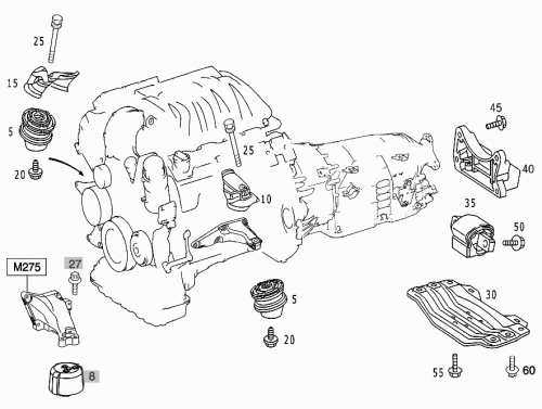
[[File:W220_epc_engine_suspension.png|500px]] | |||
The original mounts on the Mercedes-Benz are made by LEMFÖRDER. Even though genuine mounts are expensive, the general opinion is to NOT buy aftermarket brands | |||
=== Engine mounts (front) === | |||
Both mounts (left and right) have the same part number. | |||
S280/S320/S350: | |||
* A2032410413 (installed at factory) | |||
* A2032411313 | |||
* LEMFÖRDER 25390 01 | |||
S430/S500/S55 AMG (2004): | |||
* A2202403317 | |||
* LEMFÖRDER 22407 01 | |||
S600/S65 AMG 2004: | |||
* A2202400917 | |||
* LEMFÖRDER 35796 01 | |||
=== Engine mounts (rear) === | |||
All models: | |||
* A2202400218 | |||
* LEMFÖRDER 33875 01 | |||
* MEYLE 014 024 1054 (original quality) | |||
* MEYLE 014 024 1100/HD ([https://youtu.be/Ko14ENtXfNM high durability]) | |||
{| | |||
|[[File:Lemforder_25390_01.jpg|thumb|none|Front mount (LEMFÖRDER 25390 01)]] | |||
|[[File:Lemforder_33875_01.jpg|thumb|none|Rear mount (LEMFÖRDER 33875 01)]] | |||
|} | |||
{| | |||
|[[File:New Lemforder Engine Mounts 01.jpg|thumb|none|LEMFÖRDER 35796 01]] | |||
|[[File:New Lemforder Engine Mounts 02.jpg|thumb|none|LEMFÖRDER 35796 01]] | |||
|} | |||
{| | |||
|[[File:New Lemforder Engine Mounts 03.jpg|thumb|none|LEMFÖRDER 35796 01]] | |||
|[[File:New Lemforder Engine Mounts 04.jpg|thumb|none|LEMFÖRDER 35796 01]] | |||
|} | |||
== Engine mount replacement (front) == | |||
=== Remove/install front engine mounts and/or engine support === | |||
<!-- AR22.10-P-1260A Remove/install front engine mounts and/or engine support 3.11.09 | |||
ENGINES 112, 113 / (except 112.975, 113.948 /966) in MODEL 220 --> | |||
{| | |||
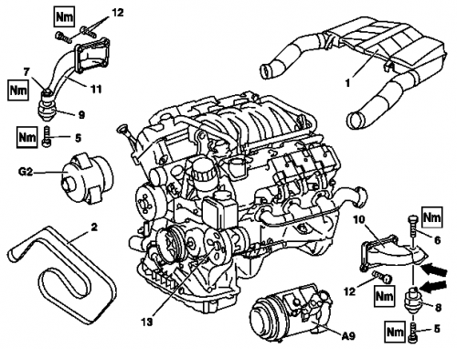
|[[File:W220_remove_install_front_engine_mounts_engine_support.png|500px]] | |||
| | |||
* 1 - Air filter housing with intake pipes | |||
* 2 - Poly-V-belt | |||
* 5 - Bolts, engine mount to front-axle carrier | |||
* 6 - Bolt for left engine mount | |||
* 7 - Bolt for right engine mount | |||
* 8 - Left engine mount | |||
* 9 - Right engine mount | |||
* 10 - Left engine support | |||
* 11 - Right engine support | |||
* 12 - Bolts on engine supports | |||
* 13 - Power steering pump | |||
* A9 - Refrigerant compressor | |||
* G2 - Alternator | |||
|} | |||
Right engine side (removal of engine mount and engine support): | |||
# Disconnect/connect battery ground line | |||
# Remove lower engine compartment paneling | |||
# Unclip cover on front end of engine | |||
# Remove air filter housing with air intake pipes (1) | |||
# Remove poly-V belt (Except engine 113.991) | |||
# Disconnect electrical lines at generator (G2). Installation: Note installation position of lines. | |||
# Detach alternator (G2) and place in the engine compartment to the side | |||
# Put on engine carrier arm | |||
# Remove engine mount (5) bolts to front axle carrier. Remove on both sides. The anti-twist locks in front axle beam must latch in retaining grooves of engine mount (8, 9). | |||
# Raise engine at front lifting eye. Ensure that rear of engine does not touch the body. | |||
# Detach right engine support (11) at crankcase, for this step unscrew bolts (12) and take out right engine support (11) with engine mount (9) toward front. Installation: Replace bolts (12). | |||
# Detach engine mount (9) from right engine support (11). Installation: The anti-twist lock () at the engine mount (9) must latch in the retaining groove in the engine support (11) (arrow). | |||
Left engine side (removal of engine mount or engine mount with engine support): | |||
# Remove power steering pump (13) | |||
# Detach refrigerant compressor (A9) from bracket and place to the side. Adjust Torx double end box wrench for lower front screw. (Tool: Torx double end box wrench for removal of refrigerant compressor) | |||
# Detach engine mount (8) from left engine support (10). Removal of engine mount (8). | |||
# Installation: The anti-twist lock () at the engine mount (8) must latch in the retaining groove in the engine support (10) (arrow). | |||
# Detach left engine support (10) at crankcase, for this step unscrew bolts (12) and take out left engine support (10) with engine mount (8) toward front. Removal of left engine support (10) and engine mount (8). Installation: Replace bolts (12). | |||
# Install in the reverse order | |||
''Note: WIS specifies removing both the engine mount AND the engine support (the portion that connects it to the engine block). This worked fine on the RIGHT mount, but on the LEFT, a hose prevented taking the mount out/or installing, in one piece. This required a combination "Bottom-Side" and "Top-Side" approach.'' | |||
=== Replacement of front engine mounts (alternative method) === | |||
Notes: | |||
* The main difference between this method and the method described in WIS is that WIS method requires removal of alternator and power steering pump. In this method the mounts are removed from underneath the car. | |||
* Caution; when you turn the left engine mount over to remove the mount-to-bracket bolt, be careful of the fluid in the mount. If the rubber has deteriorated badly, when the mount is flipped over, the fluid can pour onto your face. | * Caution; when you turn the left engine mount over to remove the mount-to-bracket bolt, be careful of the fluid in the mount. If the rubber has deteriorated badly, when the mount is flipped over, the fluid can pour onto your face. | ||
* | * If a vehicle lift is not available, put the car up on jack stands and remove the front wheels for better access under the car. | ||
* Have a hydraulic jack available to support the engine and to lift it slightly during the replacement procedure. | |||
* Disconnect the battery before starting as you do not want to short out the starter motor connection etc. | |||
* Before you start, consider purchasing a long 40mm length M8 x 1.25 bolt to be used as an alignment tool. During the procedure you will be lifting the engine slightly after releasing both engine mount bolts. If you do not want to remove both engine mounts simultaneously in order to keep the engine perfectly aligned, thread the 40mm bolt into the bottom right side mount hole 2-3 turns. This allows the right side to stay aligned while lifting the engine and replacing the left side mount. | |||
<!-- | |||
An excellent write-up for replacing the front engine mounts on an S430 by BenzWorld Member zz4x4 is here; | |||
http://www.benzworld.org/forums/showthread.php?t=1388342 | http://www.benzworld.org/forums/showthread.php?t=1388342 | ||
And is reproduced with minor editing here; | |||
--> | |||
Steps: | |||
# Open hood and remove the air intake ducts to allow room to work. | |||
# Disconnect the battery due to shock hazard working near the hot starter terminal. | |||
# Loosen front wheel nuts. | |||
# Jack up or lift vehicle to a moderate height that can allow access to the engine from the top as well as bottom. | |||
# Support the vehicle on jack stands. | |||
# Remove front wheels for better access. | |||
# Remove the lower engine cover panel under the vehicle. | |||
# Using a 13mm socket, remove both lower engine mount bolts and set aside. | |||
# Using a floor jack or suitable lifting device, raise the engine via a piece of wood under the oil pan (see photo below). The engine can be lifted about 75mm or three inches before the AC hoses begin to show signs of stress. Do not lift much further than this! | |||
# Lower the steering rack about 50mm or two inches. | |||
# Using a deep well 18mm socket, retain the nut inside the subframe channel on the two rear bolts. Using another 18mm impact socket or wrench loosen the two rear bolts. TIP: Do not fully remove the rear two bolts but make them as loose as possible while still keeping the nut on the bolt. | |||
# Completely remove the two front steering rack bolts using an 18mm open end wrench and impact socket. TIP: This will allow the rack to hang down and move forward but still allow easy re-installation. | |||
# Remove the upper engine mount bolts. TIP: On the V6 (except 4MATIC) and V8, there is little room for a socket due to the exhaust manifold. With the engine raised it is much easier to do this step though. From the top use a 16mm (or 5/8 SAE) ratcheting box end wrench and loosen the bolts (see the tools section below). They will not come out due to their length, but the engine mounts will drop off the bolts when they are loosened enough. | |||
# '''Remove the left side engine mount''' towards the front between the steering rack and subframe (see photo below). | |||
# From the bottom of the car, '''remove the right side engine mount''' rearward and pull out between the catalytic converter, bellhousing, and subframe. TIP: You may need to raise the engine a tad if it will not come out easily. It may take a little finessing and tugging to remove. TIP: On V6 engines (e.g., S350) there is enough space to remove and install right mount from the top of engine (see photo below). | |||
# Press the new mounts into the same areas the old ones came from. TIP: Get into a position under the car where you are supported and can hold the engine mount against the upper bracket with one hand and still reach the upper bolt with a couple fingers of the other hand. As you press the mount against the upper bracket, screw the bolt into the mount. Just a couple threads is all you need. Now spin the mount clockwise to tighten while keeping a finger on the bolt. After several spins, you will feel there is a place where the mount locating pin will pop into the recess on the upper mount bracket. At this point the mount will no longer spin. | |||
# You can now go to the top of the engine and fully tighten the bolt to ~55NM. TIP: Tightening the upper bolt is much easier while the engine is still lifted. | |||
# Reinstall the two front steering rack bolts / nuts and tighten all four bolts to spec. | |||
# Lower the engine slowly watching for the engine mount threaded holes to stay in alignment with the subframe holes. TIP: If side to side adjustment is necessary use a crow bar. | |||
# Reinstall lower mount bolts using Loctite and torque to ~35NM. | |||
# Reinstall air ducts, lower engine cover, connect battery and your done! | |||
Universal instruction for Mercedes-Benz cars with the V6 and V8 engine: http://www.mercedesmedic.com/diy-engine-mount-replacement-with-pictures-video-mercedes-benz/ | |||
{| | |||
|{{#ev:youtube|https://www.youtube.com/watch?v=AYqEVVxi934|320|center|W220 4MATIC (S350) engine mount replacement. On 4MATIC (S350) the engine mount replacement is easier because engine mount bolts are easily accessible. | |||
|frame}} | |||
|} | |||
{| | |||
|[[File:W220_left_engine_mount_installation_V6.jpg|thumb|none|Pushing up the new left mount between the lowered steering rack and subframe. Shown on S350.]] | |||
|[[File:W220_left_engine_mount_installed_V6.jpg|thumb|none|The new left mount installed. Shown on S350.]] | |||
|[[File:W220_right_engine_mount_installation_V6.jpg|thumb|none|Pushing down the new right mount from the top (V6 engines only). Shown on S350.]] | |||
|} | |||
== Rear engine mount (transmission mount) replacement == | |||
A rear engine mount (transmission mount) replacement is a super easy job - it takes less than 2 hours to do the job without jacking the car at all four jacking points. It actually takes more time to get the car lifted, as it does to remove and replace the mount, plus, as opposed to the "expensive" front mounts, the rear mount costs ~ 20 EUR. The procedure shown in this video is on W220 S500 (2000), but may be as applicable to many other Mercedes models of the same year and even other years. | |||
=== Remove/install rear engine mount === | |||
<!-- AR22.10-P-1160AB Remove/install rear engine mount 9.11.09 | |||
ENGINE | |||
112 (except 112.975) in MODEL 220 | |||
ENGINE | |||
137 in MODEL 215, 220 | |||
ENGINE | |||
613, 628 in MODEL 220 | |||
ENGINE | |||
113.963 in MODEL 230.475 | |||
ENGINE | |||
113.992 in MODEL 230.474 | |||
ENGINE | |||
113.991 in MODEL 215.374 | |||
ENGINE | |||
113.991 in MODEL 220.074 | |||
ENGINE | |||
275 in MODEL 215, 220, 230 | |||
ENGINE | |||
113 / (except 113.948 /966) in MODEL 215, 220 | |||
ENGINE | |||
113.995 in MODEL 230.472 | |||
--> | |||
{| | |||
|[[File:W220_remove_install_rear_engine_mount.jpg|300px]] | |||
| | |||
* 1 - Passenger car transmission platform | |||
* 2 - Rear engine mount | |||
* 3 - Engine crossmember | |||
* 4 - Bolts | |||
|} | |||
# Raise vehicle | |||
# Remove rear part of engine compartment paneling | |||
# Remove bolts (4) | |||
# Support transmission and lift somewhat | |||
# Detach rear engine mount (2) from transmission. Installation: Attach ground strap at engine mount, in order to avoid damage to electrical system. | |||
# Install in the reverse order | |||
''One suggested "variation" from the WIS technique is to not remove the crossmember. You can loosen it sufficiently to get the mount in/out if you minimally (1 or 2 cm) raise the transmission pan. This does not work on facelift vehicles as facelift has longer crossmember bolted with 4 bolts on each side (see photo below).'' | |||
{| | |||
|{{#ev:youtube|https://www.youtube.com/watch?v=8PKtLJbFVhY|320|center|Transmission mount replacement by removing the crossmember (pre-facelift).|frame}} | |||
|{{#ev:youtube|https://www.youtube.com/watch?v=L4RXNl2nkQo|320|center|Transmission mount replacement without removing the crossmember (not on W220).|frame}} | |||
|} | |||
{| | |||
|[[File:W220_engine_crossmember_facelift.jpg|thumb|none|Crossmember (facelift)]] | |||
|[[File:W220_engine_crossmember_removed_transmission_mount.jpg|thumb|none|Transmission mount (crossmember removed)]] | |||
|[[File:W220_engine_crossmember_removed_transmission_mount_removed.jpg|thumb|none|Crossmember and engine mount removed]] | |||
|} | |||
== Tools == | |||
=== Offset wrench/spanner=== | |||
A special offset wrench/spanner is available to assist with replacing engine mounts on Mercedes Benz vehicles. See [https://w220.ee/Special_Tools#Engine_Mounts_-_Special_Offset_Spanner]. | |||
Without this tool it will be very hard to unscrew the top bolt, because the bolt is under exhaust manifold. | |||
On S350 4MATIC this tool is not needed - the bolts are directly accessible. | |||
[[File:Offset_Wrench_Spanner_for_Engine_Mounts.JPG|thumb|none|16mm offset wrench]] | |||
===Engine support/raising block=== | |||
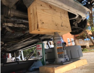
Below is a self-made lifting block that was made for supporting the V12 engine on S600 whilst changing the front engine mounts. | |||
It is a very thick (rigid) wood block to fit between the subframe rails. It should be designed to cover the entire engine | |||
sump so that the load is spread evenly across the whole sump. | |||
Then the engine may be supported and even raised slightly using an hydraulic jack. | |||
Final dimensions should be; | |||
* | * Thickness: 4 1/2” or about 115mm | ||
* Depth: 7” or about 180mm | |||
* Length: 12” or about 300mm | |||
It should be made out of three separate pieces of wood which are glued together to avoid the grain cracking. | |||
[[File:DIY Engine Raising Block.JPG|thumb|none|DIY engine support/raising block]] | |||
Latest revision as of 02:45, 18 March 2020
Engine mounts
An engine mount is the part that holds the engine in your car. In W220 the engine and transmission are bolted together and held in place by three mounts. There are two engine mounts in the front and one on the rear holding transmission (also called the transmission mount).
One part of the engine mount is bolted to the car body or frame. Another part holds the engine. An engine is a source of vibration, as it has many moving and rotating parts. The job of an engine mount is not only to hold the engine in place, but to reduce the engine vibration felt inside the car.
Engine mounts are made with a rubber material so that there is no direct metal-to-metal contact between the engine and the car body. To further dampen the vibration, front engine mounts are filled with liquid. A liquid-filled engine mount works like a shock absorber. An engine mount doesn't need any maintenance or regular servicing. It only needs to be replaced when it fails or wears out.
The most common problem with the engine mount is when the rubber part breaks or separates or when liquid starts leaking out of the liquid-filled mount. Common symptoms of a failed engine mount is the increase in engine noise and vibration felt inside the car. Often, the excessive vibration is more noticeable at idle with the transmission engaged.
How a failed engine mount is diagnosed
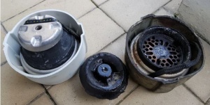
Visible signs of a failed engine mount include cracks, tears and separation in the rubber, as well as leaking liquid. See the photos above. A worn-out engine mount may appear sagging.
Before a bad engine mount is confirmed, all other causes must be eliminated. For example, when one of the exhaust pipe hangers is broken, it may create the same symptoms as a bad engine mount. When a bent or damaged exhaust pipe touches one of the chassis components, it also creates vibration and rattling noise when shifted to Drive or Reverse noticeable inside the car. Often, when one of the mounts is bad, an engine may appear seating lower on the side of the bad mount. Often when one engine mount goes bad, it adds more strain on all other mounts. For this reason, it's not uncommon to see two mounts that need replacement at the same time.
Many Mercedes-Benz owners experience vibrations through the interior of the car, the steering wheel and the seat which is the first sign that your engine mounts are failing or have failed. Sometimes a very common "shaking at idle" issue can be solved by replacing the engine mounts.
Other Mercedes-Benz owners have reported having a smooth idle until you put the car into gear, then a vibration is noticed.
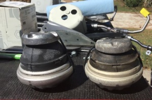
Below is an example of new and old W220 engine mounts (V12 engine). Notice how the old mount has collapsed by about one third its height. The other picture shows a complete split in two with zero hydraulic fluid remaining after 143,000 miles (230,000Km).
 |
 |
Failed front engine mounts can be diagnosed by following these steps:
- Park the car with the front pointing in a "SAFE" direction, i.e., with no one in front and a considerable distance from objects.
- Open the hood.
- Have someone apply the service AND foot brakes.
- Stand in a position to the side of the car such that you can observe the engine movement. Do not stand in front of the car.
- Ask the Helper to gently "REV" the engine on and off.
- Observe how much rotational rolling movement there is in the engine.
- Decide if the amount of engine movement is excessive. You will know what "excessive" is. If the engine was rocking and rolling SEVERAL inches up and down you have bad engine mounts!
Part numbers
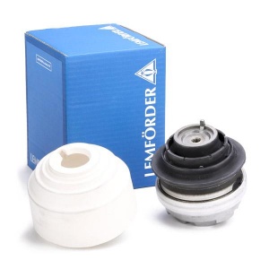
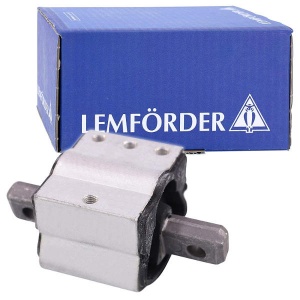
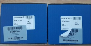
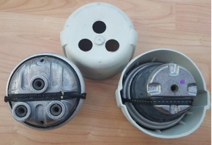
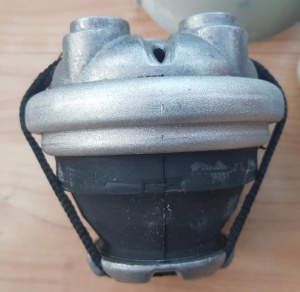
The original mounts on the Mercedes-Benz are made by LEMFÖRDER. Even though genuine mounts are expensive, the general opinion is to NOT buy aftermarket brands
Engine mounts (front)
Both mounts (left and right) have the same part number.
S280/S320/S350:
- A2032410413 (installed at factory)
- A2032411313
- LEMFÖRDER 25390 01
S430/S500/S55 AMG (2004):
- A2202403317
- LEMFÖRDER 22407 01
S600/S65 AMG 2004:
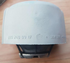
- A2202400917
- LEMFÖRDER 35796 01
Engine mounts (rear)
All models:
- A2202400218
- LEMFÖRDER 33875 01
- MEYLE 014 024 1054 (original quality)
- MEYLE 014 024 1100/HD (high durability)
 |
 |
 |
 |
 |
 |
Engine mount replacement (front)
Remove/install front engine mounts and/or engine support
Right engine side (removal of engine mount and engine support):
- Disconnect/connect battery ground line
- Remove lower engine compartment paneling
- Unclip cover on front end of engine
- Remove air filter housing with air intake pipes (1)
- Remove poly-V belt (Except engine 113.991)
- Disconnect electrical lines at generator (G2). Installation: Note installation position of lines.
- Detach alternator (G2) and place in the engine compartment to the side
- Put on engine carrier arm
- Remove engine mount (5) bolts to front axle carrier. Remove on both sides. The anti-twist locks in front axle beam must latch in retaining grooves of engine mount (8, 9).
- Raise engine at front lifting eye. Ensure that rear of engine does not touch the body.
- Detach right engine support (11) at crankcase, for this step unscrew bolts (12) and take out right engine support (11) with engine mount (9) toward front. Installation: Replace bolts (12).
- Detach engine mount (9) from right engine support (11). Installation: The anti-twist lock () at the engine mount (9) must latch in the retaining groove in the engine support (11) (arrow).
Left engine side (removal of engine mount or engine mount with engine support):
- Remove power steering pump (13)
- Detach refrigerant compressor (A9) from bracket and place to the side. Adjust Torx double end box wrench for lower front screw. (Tool: Torx double end box wrench for removal of refrigerant compressor)
- Detach engine mount (8) from left engine support (10). Removal of engine mount (8).
- Installation: The anti-twist lock () at the engine mount (8) must latch in the retaining groove in the engine support (10) (arrow).
- Detach left engine support (10) at crankcase, for this step unscrew bolts (12) and take out left engine support (10) with engine mount (8) toward front. Removal of left engine support (10) and engine mount (8). Installation: Replace bolts (12).
- Install in the reverse order
Note: WIS specifies removing both the engine mount AND the engine support (the portion that connects it to the engine block). This worked fine on the RIGHT mount, but on the LEFT, a hose prevented taking the mount out/or installing, in one piece. This required a combination "Bottom-Side" and "Top-Side" approach.
Replacement of front engine mounts (alternative method)
Notes:
- The main difference between this method and the method described in WIS is that WIS method requires removal of alternator and power steering pump. In this method the mounts are removed from underneath the car.
- Caution; when you turn the left engine mount over to remove the mount-to-bracket bolt, be careful of the fluid in the mount. If the rubber has deteriorated badly, when the mount is flipped over, the fluid can pour onto your face.
- If a vehicle lift is not available, put the car up on jack stands and remove the front wheels for better access under the car.
- Have a hydraulic jack available to support the engine and to lift it slightly during the replacement procedure.
- Disconnect the battery before starting as you do not want to short out the starter motor connection etc.
- Before you start, consider purchasing a long 40mm length M8 x 1.25 bolt to be used as an alignment tool. During the procedure you will be lifting the engine slightly after releasing both engine mount bolts. If you do not want to remove both engine mounts simultaneously in order to keep the engine perfectly aligned, thread the 40mm bolt into the bottom right side mount hole 2-3 turns. This allows the right side to stay aligned while lifting the engine and replacing the left side mount.
Steps:
- Open hood and remove the air intake ducts to allow room to work.
- Disconnect the battery due to shock hazard working near the hot starter terminal.
- Loosen front wheel nuts.
- Jack up or lift vehicle to a moderate height that can allow access to the engine from the top as well as bottom.
- Support the vehicle on jack stands.
- Remove front wheels for better access.
- Remove the lower engine cover panel under the vehicle.
- Using a 13mm socket, remove both lower engine mount bolts and set aside.
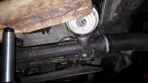
- Using a floor jack or suitable lifting device, raise the engine via a piece of wood under the oil pan (see photo below). The engine can be lifted about 75mm or three inches before the AC hoses begin to show signs of stress. Do not lift much further than this!
- Lower the steering rack about 50mm or two inches.
- Using a deep well 18mm socket, retain the nut inside the subframe channel on the two rear bolts. Using another 18mm impact socket or wrench loosen the two rear bolts. TIP: Do not fully remove the rear two bolts but make them as loose as possible while still keeping the nut on the bolt.
- Completely remove the two front steering rack bolts using an 18mm open end wrench and impact socket. TIP: This will allow the rack to hang down and move forward but still allow easy re-installation.
- Remove the upper engine mount bolts. TIP: On the V6 (except 4MATIC) and V8, there is little room for a socket due to the exhaust manifold. With the engine raised it is much easier to do this step though. From the top use a 16mm (or 5/8 SAE) ratcheting box end wrench and loosen the bolts (see the tools section below). They will not come out due to their length, but the engine mounts will drop off the bolts when they are loosened enough.
- Remove the left side engine mount towards the front between the steering rack and subframe (see photo below).
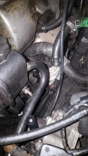
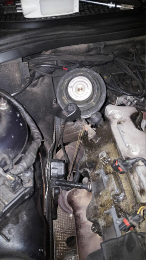
- From the bottom of the car, remove the right side engine mount rearward and pull out between the catalytic converter, bellhousing, and subframe. TIP: You may need to raise the engine a tad if it will not come out easily. It may take a little finessing and tugging to remove. TIP: On V6 engines (e.g., S350) there is enough space to remove and install right mount from the top of engine (see photo below).
- Press the new mounts into the same areas the old ones came from. TIP: Get into a position under the car where you are supported and can hold the engine mount against the upper bracket with one hand and still reach the upper bolt with a couple fingers of the other hand. As you press the mount against the upper bracket, screw the bolt into the mount. Just a couple threads is all you need. Now spin the mount clockwise to tighten while keeping a finger on the bolt. After several spins, you will feel there is a place where the mount locating pin will pop into the recess on the upper mount bracket. At this point the mount will no longer spin.
- You can now go to the top of the engine and fully tighten the bolt to ~55NM. TIP: Tightening the upper bolt is much easier while the engine is still lifted.
- Reinstall the two front steering rack bolts / nuts and tighten all four bolts to spec.
- Lower the engine slowly watching for the engine mount threaded holes to stay in alignment with the subframe holes. TIP: If side to side adjustment is necessary use a crow bar.
- Reinstall lower mount bolts using Loctite and torque to ~35NM.
- Reinstall air ducts, lower engine cover, connect battery and your done!
Universal instruction for Mercedes-Benz cars with the V6 and V8 engine: http://www.mercedesmedic.com/diy-engine-mount-replacement-with-pictures-video-mercedes-benz/
Rear engine mount (transmission mount) replacement
A rear engine mount (transmission mount) replacement is a super easy job - it takes less than 2 hours to do the job without jacking the car at all four jacking points. It actually takes more time to get the car lifted, as it does to remove and replace the mount, plus, as opposed to the "expensive" front mounts, the rear mount costs ~ 20 EUR. The procedure shown in this video is on W220 S500 (2000), but may be as applicable to many other Mercedes models of the same year and even other years.
Remove/install rear engine mount
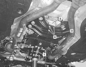
|
|
- Raise vehicle
- Remove rear part of engine compartment paneling
- Remove bolts (4)
- Support transmission and lift somewhat
- Detach rear engine mount (2) from transmission. Installation: Attach ground strap at engine mount, in order to avoid damage to electrical system.
- Install in the reverse order
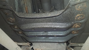
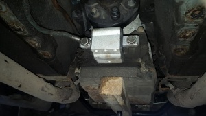
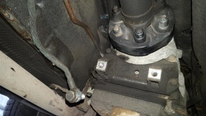
One suggested "variation" from the WIS technique is to not remove the crossmember. You can loosen it sufficiently to get the mount in/out if you minimally (1 or 2 cm) raise the transmission pan. This does not work on facelift vehicles as facelift has longer crossmember bolted with 4 bolts on each side (see photo below).
 |
 |
 |
Tools
Offset wrench/spanner
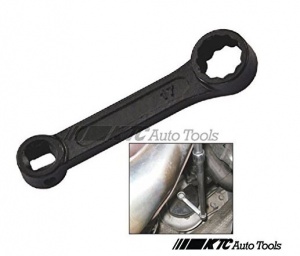
A special offset wrench/spanner is available to assist with replacing engine mounts on Mercedes Benz vehicles. See [1].
Without this tool it will be very hard to unscrew the top bolt, because the bolt is under exhaust manifold. On S350 4MATIC this tool is not needed - the bolts are directly accessible.
Engine support/raising block
Below is a self-made lifting block that was made for supporting the V12 engine on S600 whilst changing the front engine mounts. It is a very thick (rigid) wood block to fit between the subframe rails. It should be designed to cover the entire engine sump so that the load is spread evenly across the whole sump.
Then the engine may be supported and even raised slightly using an hydraulic jack.
Final dimensions should be;
- Thickness: 4 1/2” or about 115mm
- Depth: 7” or about 180mm
- Length: 12” or about 300mm
It should be made out of three separate pieces of wood which are glued together to avoid the grain cracking.
