Door control module: Difference between revisions
| Line 40: | Line 40: | ||
[[File:W220_door_control_module_connected.jpg|thumb|none|Front left door control module connected.]] | [[File:W220_door_control_module_connected.jpg|thumb|none|Front left door control module connected.]] | ||
== Seat heating and ventilation == | == Seat heating and ventilation == | ||
Revision as of 20:13, 14 February 2017
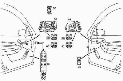
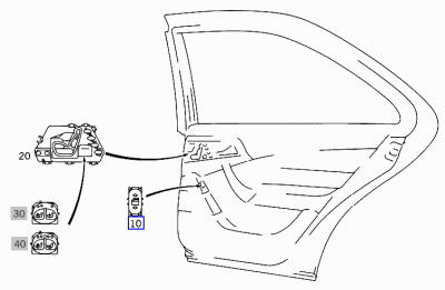
Door control module (in WIS) or Electric Seat Adjuster Switch (in EPC) is electrical part responsible for several tasks. When looking for part in catalogs, you may need to add color code to end of the part number (e.g., A22082106587C45).
Functionality
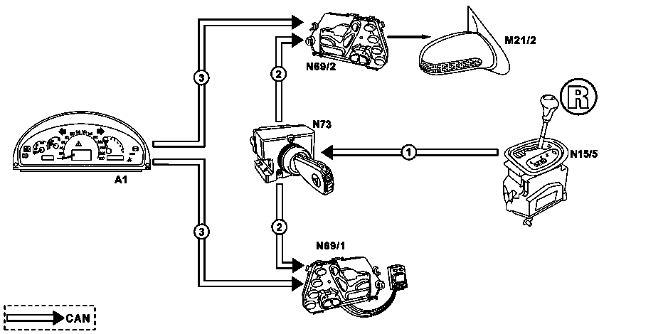
The door control module in itself is a pretty dumb device. All key presses are sent over CANBUS to SAM. SAM then broadcasts message to all modules and module which understands the message acts appropriately (whether lighting up some bulb, engaging seat heating, moving seat, etc.).
DCM is responsible for:
- External mirror:
- Lighting up mirror turn signal light
- Lighting up mirror courtesy light
- Mirror heating
- Mirror angle altering
- Mirror fold-in
- Receiving signal from infrared receiver
- Engaging door power close
- Opening door window
- Receiving signal from window control switch
- receiving signal from trunk open switch
- Receiving signal from mirror control switch
- Powering door handle LED
- Powering door courtesy light
- Receiving signal from seat regulation switch
Power for driver side front DCM is controlled by fuse X.
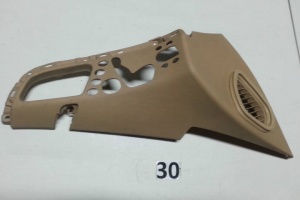
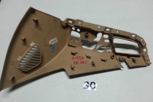
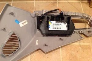
Location
DCM is located in door trim held by plastic clips.
 |
 |
 |
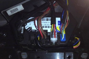
Connectors
Seat heating and ventilation
Seat heating
All W220s are equipped with seat heating feature for front seats.
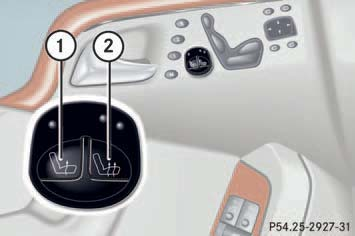
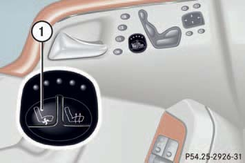
Seat heating has three modes:
- Rapid heating (two lamps on)
- Normal heating (one lamp on)
- No heating (lamps off)
The system switches from the rapid heating mode to normal heating mode after approximately five minutes. The seat heating will be automatically switched off after approximately 30 minutes.
Seat ventilation
Vehicles with option code 401 are equipped also with the seat ventilation feature.
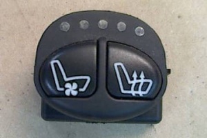
The blue indicator lamps on the switch show the ventilation level selected.
Seat ventilation can be activated manually with the SmartKey in starter switch position 1 or 2.
The driver's seat ventilation can be activated to the highest level automatically by the summer opening feature.
Rear seats are heated in vehicles with option code 872. In vehicles with option code 402 rear seats are heated and ventilated.
Note: If one or all of the lamps on the seat ventilation switch are flashing, there is insufficient voltage since too many electrical consumers are switched on. The seat ventilation and heating switches off automatically. The seat ventilation and heating will switch back on again automatically as soon as sufficient voltage is available.
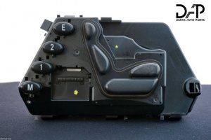
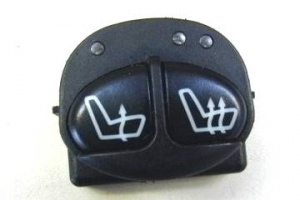
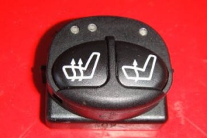
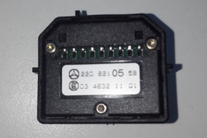
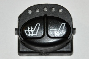
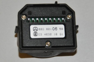
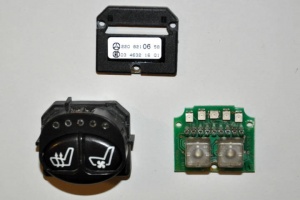
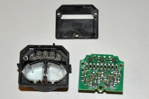
Heated and/or ventilated seat buttons
Seat ventilation functionality does not depend on the specific DCM used. Appropriate buttons are not part of DCM and can be bought separately.
It is possible to use heated and ventilated button for engaging heating on vehicle without ventilation. It is possible to use heated button on vehicle with seat ventilation, however, not all heating and ventilating states can be engaged.
 |
 |
 |
 |
 |
 |
 |
 |
 |
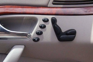
Memory function
The settings for the left and right exterior mirrors, the interior
rearview mirror and the steering column are also stored together
with the driver's seat setting.
Up to 31.05.01
- Driver's side: For each transmitter key, two complete seat settings can be stored and called up again on the driver's side. A total of eight memory areas are available.
- Front passenger's side: On the front passenger's side, two complete seat settings can be stored and called up again.
As of 01.06.01
- Driver's side: For each transmitter key, three complete seat settings can now be stored and called up again on the driver's side. A total of twelve memory areas are available.
- Front passenger's side: On the front passenger's side, three complete seat settings can now be stored and called up again.
- Rear (only model 220 with electrically adjustable individual rear seats): Three complete seat settings can be stored and called up again.
Calling up stored positions function
Calling up stored positions (driver, front passenger)
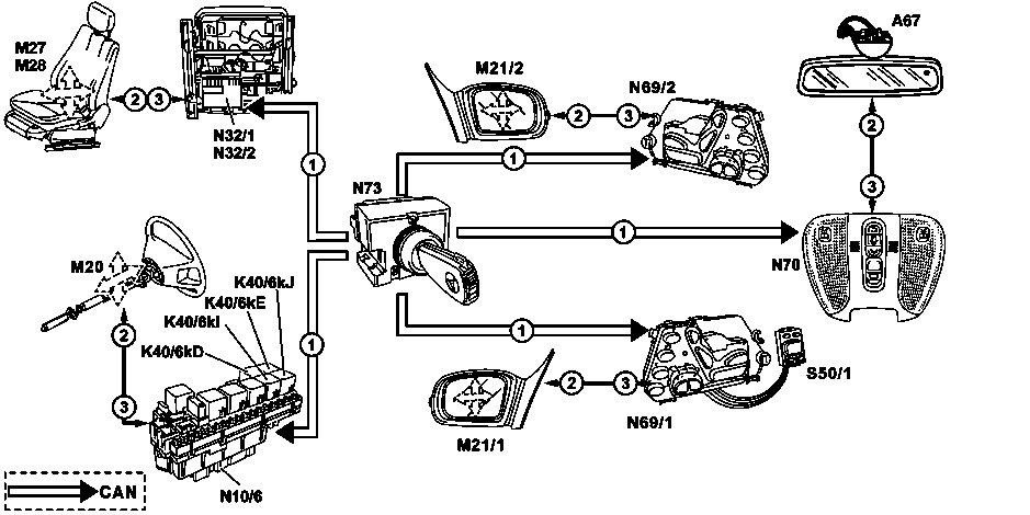
|
|
Function requirements:
- No overvoltage or undervoltage
- Term.15R or 15 ON
- Driver's door/front passenger's door open
- No button for manual seat adjustment, mirror adjustment or steering column adjustment pressed
- Normalization carried out properly
Calling up memory and Ergo positions (driver) up to 31.5.01. When calling up the memory function or Ergo function by pressing the memory 1 switch (N69/1s6), memory 2 switch (N69/1s7) or ERGONOMICS switch (N69/1s8) in the left door control module (N69/1) the positions stored in the relevant control modules are actuated:
- Inside rearview mirror
- Front passenger's exterior mirror
- Steering column
- Driver seat
The left front door control module (N69/1) recognizes that a switch is pressed and sends the following message via the CAN: "Left front memory - Assume position 1/2/Ergo". Memory 3 (N69/1s15), in the left front door control module (N69/1).
This message is received from the left front SAM control module (N10/6), from the overhead control panel control module (N70), from the right front door control module (N69/2) and from the left front seat adjustment control module with memory (N32/1).
Consequently these control modules, and also the left front [[door control module]] (N69/1), actuate the respective motors (see Figure), when the button is pressed further, until it is recognized via the local position recognitions that the stored positions are reached.
As of 1.6.01 the Ergo position is not used anymore, it is replaced by a further memory button. This memory location is called up by pressing the switch for memory 3 (N69/1s9) in the left front door control module (N69/1).
Calling up memory/Ergo positions (front passenger) up to 31.5.01. When the memory feature is called up by pressing the memory 1 switch (N69/2s6), memory 2 switch (N69/2s7) ERGONOMY switch (N69/2s9) in the right front door control module (N69/2), the positions of the front passenger's seat stored in the right front seat adjustment control module with memory (N32/2) are approached. The right front door control module (N69/2) recognizes that a switch is pressed and places the following message on the CAN: "Right front memory - Assume position 1/2/Ergo". This message is received from right front seat adjustment control module with memory (N32/2) which then, when the button is pressed further, actuates the motors of the right front seat adjustment motor group with memory (M28) until it is recognized via local position recognitions that the stored positions are reached.
As of 1.6.01 the Ergo position is not used anymore, it is replaced by a further memory button. This memory location is called up by pressing the memory 3 switch (N69/2s15) in the right front control module (N69/2).
Calling up memory positions (rear). (On model 220 with electrically adjustable individual rear seats with memory)
Left rear side: When the memory feature is called up by pressing the memory 1 switch (N69/3s3) or memory 2 switch (N69/4s4) or memory 3 switch(N69/3s5) in the driver's side door control module (N69/3) the positions of the left rear seat stored in the rear seats control module (N25/6) are approached.
Right rear side: When the memory feature is called up by pressing the memory 1 switch (N69/4s3) or memory 2 switch (N69/3s4) or memory 3 switch (N69/4s5) in the right rear door control module (N69/4) the respective door control module recognizes that a switch is pressed and places the following message on the CAN "Left and right rear memory - Assume position 1/2/3". This message is received by the rear seats control module (N25/6) which then, if the button is pressed further, actuates the respective adjustment motors until it is recognized via local position recognitions that the stored positions are reached.
Storing memory positions function
Function prerequisites:
- Circuit 15R or 15 ON
Together with the storage of the driver's seat position in addition the inside rearview mirror, the outside mirror as well as the steering column position are stored in the relevant control module key-related.
Memory locations up to 31.5.01. The positions of the driver's seat and front passenger's seat including the adjustments of the multicontour backrest (special equipment) can be stored on two memory locations.
Memory locations as of 1.6.01 The positions of the driver's seat and front passenger's seat including the adjustments of the multicontour backrest (special equipment) can be stored on three memory locations.
The positions are stored in the following control modules:
Driver side:
- Seat position: Left front seat adjustment control module with memory (N32/1)
- Inside rearview mirror position: Overhead control panel control module (N70)
- Left outside mirror: Left front door control module (N69/1)
- Right outside mirror: Right front door control module (N69/2)
- Steering column position: Left front SAM control module (N10/6)
Passenger side:
- Seat position: Right front seat adjustment control module with memory (N32/2)
Rear seats (model 220 with electrically adjustable individual rear seats only):
- Seat position: Rear seats control module (N25/6)
Up to 31.5.01 storing driver's seat position with associated mirror and steering column positions. The currently adjusted positions are stored by pressing the memory switch (N69/1s9) in the left front door control module (N69/1) and then within 3 seconds, the memory 1 switch (N69/1s6) or memory 2 switch (N69/1s7).
If at the same time no other switch in this switch group is pressed, the left front door control module (N69/1) sends a message to the CAN. The respective control modules receive this request for position storage and check whether valid values are supplied via local position measurements. If this is the case, the current positions are stored in the non-volatile memory.
Up to 31.5.01 storing front passenger's seat position. The currently adjusted front passenger's seat position is stored in the same way as the driver's seat position. It is triggered by pressing the memory switch (N69/2s9) in the right front door control module (N69/2) and then, within 3 seconds, memory 1 switch (N69/2s6) or memory 2 switch (N69/2s7)
Storing left rear seat position (model 220 with electrically adjustable individual rear seats only). The currently adjusted rear seat position is stored by pressing the memory switch (N69/3s10) in the left rear door control module (N69/3) and then memory switch 1 within 3 seconds (N69/3s3) or memory 2 switch (N69/3s4) or memory 3 switch (N69/3s5).
The storage process for the right rear side is analog to the left rear side. In the process the memory switch (N69/4s10) in the right rear door control module (N69/4) and memory 1 switch (N69/4s3) or memory 2 switch (N69/4s4) or memory 3 switch (N69/4s5) are used.
As of 1.6.01 revised storage process. There are two ways of storing the respective positions:
For the driver's side: a) If the memory switch (N69/1s9) is kept pressed and additionally one of the memory 1 switches (N69/1s6), memory 2 switches (N69/1s7); memory 3 switches (N69/1s15) is pressed for t>=40 ms, the storage process is thereby concluded.
b) Press the memory switch (N69/1s9) for t=>40 ms and then release again, then within t<3 seconds, press the desired memory location via memory 1 switch (N69/1s6); memory 2 switch (N69/1s7), memory 3 switch (N69/1s15) for t>=40 ms so that the storage process is concluded.
In order to avoid faults during storage it is necessary that the voltage supply is applied to the control module for a further five seconds at least.
If during the storage process no other switch from the switch group is pressed, the values are sent from the respective door control module to the relevant control modules via the CAN. These control modules check whether the local position measurement supplies valid values. If this is the case the current positions are stored in the non-volatile memory.
The storage process for the front passenger's side is analog to the driver's side. In the process the memory 1 switch (N69/2s6), memory 2 switch (N69/2s7), memory 3 switch (N69/2s15) and memory switch (N69/2s9) are used.
The driver's seat position (memory feature) is stored in the left front seat adjustment control module with memory (N32/1) (vehicle with right hand steering (N32/2)) on a key-related basis.
The electronic ignition switch control module (N73) recognizes the inserted transmitter key (A8/1) and notifies the left front seat adjustment control module with memory (N32/1) (vehicles with right hand steering: right front seat adjustment control module with memory (N32/2)) which of the four memory blocks are to be activated via the CAN. One memory block consists of two memory areas. One complete seat position can be stored for each memory area. The memory area is selected via the memory 1 switch (N69/1s6)/memory 2 switch (N69/1s7) in the left front door control module (N69/1) (vehicle with right hand steering: Corresponding switches in the right front door control module (N69/2)).
| Key track | 1 | 2 | 5/6 | 3/4/7/8 |
|---|---|---|---|---|
| Memory block number (CAN message from electronic ignition switch) | 1 | 2 | 3 | 4 |
| Position key on left front door control module (N69/1) | 1 2 | 1 2 | 1 2 | 1 2 |
| Memory area in the left front seat adjustment control module with memory (N32/1) (LHS) | 1 2 | 3 4 | 5 6 | 7 8 |
Parking position for exterior rearview mirror on passenger side function
Moving the exterior rearview mirror on the passenger side to the parking position when reverse gear is engaged (illustrated on vehicle with left-hand steering)
Function prerequisites
- Voltage not too low or too high
- C.15 ON
- Reverse gear engaged
- Exterior mirror changeover left/right switch (S50/1s3) in passenger-side rearview mirror position
- Position measurement supplying valid values
Purpose of parking position. After the exterior rearview mirror on the passenger side has moved to the parking position the driver can observe the distance between the associated rear wheel and edge of the curb in the mirror when backing up to park the car.
Function. The right front door control module (N69/2) (vehicles with right-hand steering: left front door control module (N69/1) ) receives the CAN message "Reverse gear engaged", causing the exterior rearview mirror on the passenger side to be moved to the parking position stored for ignition/starter key in use.
One parking position can be stored in the right front door control module (N69/2) (vehicles with right-hand steering: left front door control module (N69/1)) per ignition/starter key.
Termination of function. The exterior rearview mirror is automatically moved back to the original position when:
- The transmission is shifted to a forward gear, after expiration of a time of approx. 10s
- or the vehicle speed increases to about 10 km/h or
- the exterior mirror changeover left/right switch (S50/1s3) in the exterior mirror adjustment switch with mirror fold-in/out feature (S50/1) on the left front door control module (N69/1) (vehicles with right-hand steering: right front door control module (N69/2)) has been actuated.
The mirror is also moved back to the original position even when it was adjusted manually in the parking position with the adjustment switch.
Storing parking position for exterior rearview mirror function
Function prerequisites:
- C. 15R or c.15 ON
- Vehicle speed v=0 km/h
The parking position for the exterior mirror on the passenger side can be stored in relation to the key with the left front door control module (N69/1) (vehicles with right-hand steering: right front door control module (N69/2)).
For this purpose it is first necessary to adjust the rearview mirror to the desired parking position manually with the mirror adjustment switches in the exterior mirror adjustment switch group with mirror fold-in/out feature (S50/1).
Then press the memory switch (N69/1s9) (vehicles with right-hand steering: (N69/2s9)), and within 3 seconds the bottom half of the rocker switch of the exterior mirror adjustment up/down switch (S50/1s1). When this combination of buttons is pressed the left front door control module (N69/1) transmits the CAN message "Store parking position" to the right front door control module (N69/2) (vehicles with right-hand steering: vice versa). The momentary exterior rearview mirror position is then stored as the parking position.
Retrofitting memory function
It seems that at least facelift W220 comes with seats/mirrors that support memory function. The only missing part to enable memory function is DCM with memory buttons. Even more, installing switch board with buttons from DCM that has them will allow to use memory function without need for whole DCM replacement.
For example, it has been tested that vehicle originally equipped with DCM A2208214179 in drivers doors can be replaced with DCM A2208211579 and memory seats will work out of the box. To mount DCM with memory buttons into the doors, the door panel with holes for memory buttons must also be retrofitted.
Mirror Adjustment
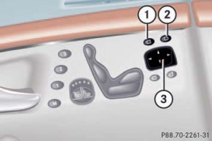
- Driver’s side exterior rear view mirror button
- Passenger-side exterior rear view mirror button
- Adjustment button
Mirror adjustment switch is not part of DCM, but connects to it.
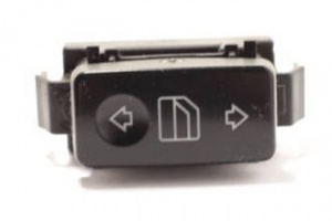
Window control switch
Driver's door switch
For facelift vehicles driver's doors have part number A2208213179 (for both left hand and right hand drive vehicles). Although visually the same EPC lists part A2208213279 for vehicles equipped with remote trunk locking (option code 881).
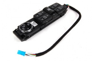
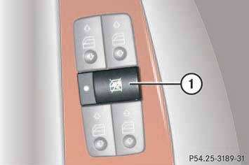
Override switch
You can disable the following functions in the rear passenger compartment for instance when you have children riding in the rear passenger compartment):
- rear door window operation
- adjustment of front passenger seat from the rear (option code 247)
- cigarette lighter in rear
To activate slide override switch (1) to the right. A dot becomes visible. The functions in the rear are disabled.
Note: Operation of the rear door windows with the switches located in the driver's door is still possible.
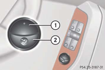
Trunk lid switch
You can open the trunk from the inside if the vehicle is stationary. Pull remote trunk lid switch (2) until trunk begins to open. The trunk lid opens. The indicator lamp (1) comes on and remains lit until the trunk is closed.
You can close the trunk from the inside if the vehicle is equipped with option code 881. To close press remote trunk lid switch (2) until the indicator lamp (1) goes out and trunk lid is closed.
Other door switch
In all doors except driver's door, the switch with part number A2208213379 is used.
Using right hand drive DCM in left hand drive vehicle
It has been tested that RHD DCM A2208212179 installed on left side of LHD vehicle originally equipped with A2208214179 will work fine, however, the mirror controlling switch will not work and window controlling switch will be able open only driver's door window. Similarly, RHD DCM A2208211879 installed on left side of LHD vehicle originally equipped with A2208214979 will work fine, however, the window opening switch will open left side driver's door window.
Using left DCM on the right side
The physical location of DCM is programmed into DCM. E.g., if left DCM is connected to right side, the DCM will still move left seat.
Using pre-facelift DCM in facelift vehicle
Has not been tested.
List of door control modules
Early DCM had weak protection against moisture and therefore could be easily damaged if the door window was left open while raining. In later DCMs MB has improved protection against moisture. When looking for replacement DCM buy the latest compatible DCM in the category.
Facelift (from 30/09/2002)
Front Left
| Part No. | Front | Back |
|---|---|---|
| A2208214179 (left hand drive vehicles) | photo | photo |
| A2208211579 (left hand drive vehicles) with memory | photo | photo |
| A2208214479 (right hand drive vehicles) | photo | photo |
| A2208212179 (right hand drive vehicles) with memory | photo | photo |
Front Right
| Part No. | Front | Back |
|---|---|---|
| A2208214979 (left hand drive vehicles) | photo | photo |
| A2208211679 (left hand drive vehicles) with memory | photo | photo |
| A2208215079 (right hand drive vehicles) | ||
| A2208211879 (right hand drive vehices) with memory | photo | photo |
Rear Left
| Part No. | Front | Back |
|---|---|---|
| A2208216279 | photo | photo |
| A2208215779 | photo | photo |
| A2208212379 | photo | photo |
| A2208212779 (right hand drive vehicles) | photo | photo |
Rear Right
| Part No. | Front | Back |
|---|---|---|
| A2208216879 | photo | photo |
| A2208216379 | photo | photo |
| A2208212479 | photo | photo |
| A2208212879 (left hand drive vehicles) | photo | photo |
Pre-facelift (to 01/09/2002)
Front Left
| Part No. | Front | Back |
|---|---|---|
| A2208208710 (left hand drive vehicles, to date 29/07/1999, replaced by A2208218751) | photo | |
| A2208218751 (left hand drive vehicles, to date 30/06/2011) | photo | photo |
| A2208212958 (left hand drive vehicles, from date 30/06/2001 to date 01/09/2002) | ||
| A2208200110 (left hand drive vehicles, to date 29/07/1999, replaced by A2208219351) | photo | photo |
| A2208219351 (left hand drive vehicles, to date 30/06/2001) | photo | photo |
| A2208213358 (left hand drive vehicles, from date 30/06/2001 to date 01/09/2002) | photo | photo |
| A2208208910 (right hand drive vehicles, to date 30/06/2001, replaced by A2208219151) | photo | |
| A2208219151 (right hand drive vehicles, to date 30/06/2001) | photo | photo |
| A2208213158 (right hand drive vehicles, from date 30/06/2001 to date 01/09/2002) | photo | photo |
| A2208202610 (right hand drive vehicles, to date 30/06/2001, replaced by A2208219751) | photo | photo |
| A2208219751 (right hand drive vehicles, to date 30/06/2001) | photo | photo |
| A2208213758 (right hand drive vehicles, from date 30/06/2001 to date 01/09/2002) | photo | photo |
Front Right
| Part No. | Front | Back |
|---|---|---|
| A2208208810 (left hand drive vehicles, to date 30/06/2001, replaced by A2208219251) | photo | photo |
| A2208219251 (left hand drive vehicles, to date 30/06/2001) | photo | photo |
| A2208213258 (left hand drive vehicles, from date 30/06/2001 to date 01/09/2002) | photo | photo |
| A2208200110 (left hand drive vehicles, to date 30/06/2011, replaced by A2208219851) | photo | photo |
| A2208219851 (left hand drive vehicles, to date 30/06/2011) | photo | photo |
| A2208213858 (left hand drive vehicles, from date 30/06/2001 to date 01/09/2002) | photo | photo |
| A2208209010 (right hand drive vehicles, to date 29/06/1999, replaced by A2208218851) | photo | photo |
| A2208218851 (right hand drive vehicles, to date 01/09/2002) | photo | photo |
| A2208202710 (right hand drive vehicles, to date 30/06/2011, replaced by A2208219451) | photo | photo |
| A2208219451 (right hand drive vehicles, to date 30/06/2011) | photo | photo |
| A2208213458 (right hand drive vehicles, from date 30/06/2001 to date 01/09/2002) | photo | photo |
Rear Left
| Part No. | Front | Back |
|---|---|---|
| A2208214351 (to date 30/06/2001, replaced by A2208211558) | photo | photo |
| A2208211558 (to date 30/06/2001, replaced by A2208214958) | photo | photo |
| A2208214958 | photo | photo |
| A2208203310 (to date 30/06/2011, replaced by A2208210958) | photo | photo |
| A2208210958 (to date 30/06/2011, replaced by A2208214758) | photo | photo |
| A2208214758 | photo | photo |
| A2208200310 (to date 30/06/2011, replaced by A2208211358) | photo | photo |
| A2208211358 (to date 30/06/2011, replaced by A2208215158) | photo | photo |
| A2208215158 | photo | photo |
| A2208214551 (right hand drive vehicles, replaced by A2208218351) | photo | photo |
| A2208218351 (right hand drive vehicles, replaced by A2208215558) | photo | |
| A2208215558 (right hand drive vehicles) | photo | photo |
Rear Right
| Part No. | Front | Back |
|---|---|---|
| A2208214451 (to 30/06/2001, replaced by A2208211658) | photo | photo |
| A2208211658 (to 30/06/2001, replaced by A2208215058) | photo | photo |
| A2208215058 | photo | photo |
| A2208203410 (to 30/06/2001, replaced by A2208211058) | photo | photo |
| A2208211058 (to 30/06/2001, replaced by A2208214858) | photo | photo |
| A2208214858 | photo | photo |
| A2208200410 (to 30/06/2001, replaced by A2208211458) | photo | photo |
| A2208211458 (to 30/06/2001, replaced by A2208215258) | photo | photo |
| A2208215258 | photo | photo |
| A2208214651 (left hand drive vehicles, replaced by A2208218451) | photo | photo |
| A2208218451 (left hand drive vehicles, replaced by A2208215658) | photo | photo |
| A2208215658 (left hand drive vehicles) | photo | photo |
Resources
Making your own DCM control buttons: http://www.benzworld.org/forums/w220-s-class/1624796-seeking-rh-headrest-adjuster-button.html
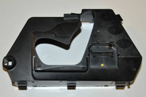
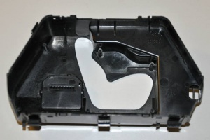
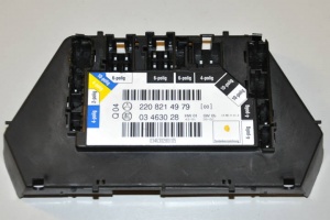
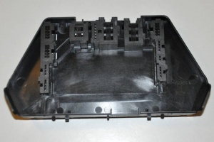
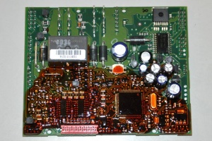
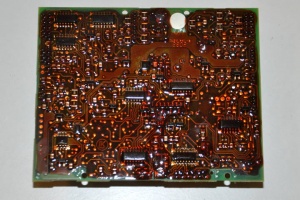
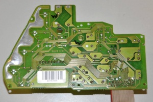
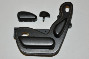
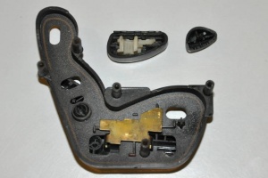
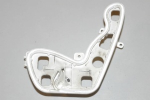
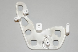
Dissecting DCM (A2208214979)
Left-hand-drive right front DCM (without memory function) dissected. The process of disassembling did not cause damage - all parts pictured can be reassembled back.
 |
 |
 |
 |
 |
 |
 |
 |
 |
 |
 |
 |
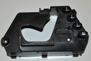
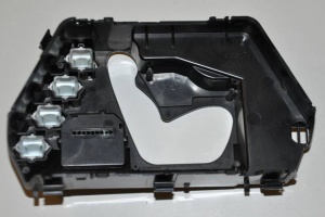
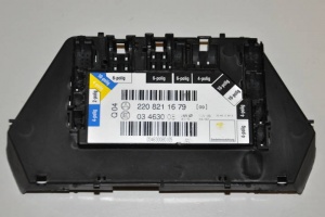
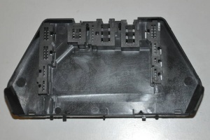
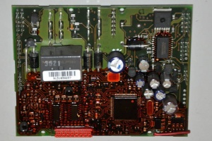
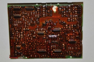
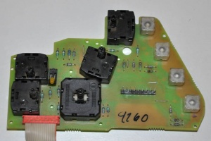
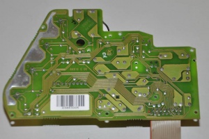
Dissecting DCM (A2208211679)
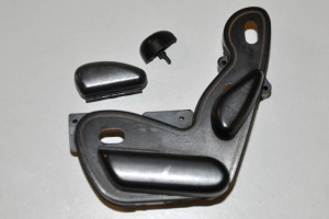
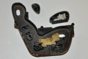
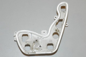
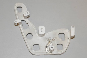
Left-hand-drive right front DCM (with memory function) dissected. The process of disassembling did not cause damage - all parts pictured can be reassembled back.
 |
 |
 |
 |
 |
 |
 |
 |
 |
 |
 |
 |
