Connects2 CT90-MC04: Difference between revisions
(General description) |
(Installation) |
||
| Line 21: | Line 21: | ||
== Kit Contents == | == Kit Contents == | ||
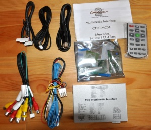
[[File:W220_CT90-MC04_kit_contents.jpg|thumb|none|CT90-MC04 package contents.]] | |||
{| | {| | ||
| Line 40: | Line 42: | ||
== Interface Connections == | == Interface Connections == | ||
[[File:W220_CT90-MC04_Interface_Connections.jpg|600px|none]] | [[File:W220_CT90-MC04_Interface_Connections.jpg|600px|none]] | ||
== Installation == | |||
{| | |||
|[[File:W220_CT90-MC04_install_1.jpg|thumb|none|W220 COMAND.]] | |||
|[[File:W220_CT90-MC04_install_2.jpg|thumb|none|Remove the screws from the indicated positions.]] | |||
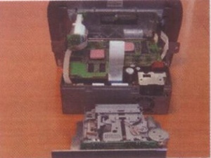
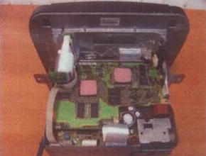
|[[File:W220_CT90-MC04_install_3.jpg|thumb|none|Take apart the case and unplug the indicated flat cable.]] | |||
|} | |||
{| | |||
|[[File:W220_CT90-MC04_install_4.jpg|thumb|none|Remove the screws from the indicated positions.]] | |||
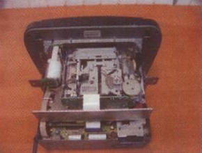
|[[File:W220_CT90-MC04_install_5.jpg|thumb|none|Remove the cassette mechanism.]] | |||
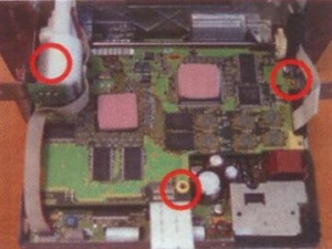
|[[File:W220_CT90-MC04_install_6.jpg|thumb|none|Remove the 3 screws from the indicated positions.]] | |||
|} | |||
{| | |||
|[[File:W220_CT90-MC04_install_7.jpg|thumb|none|Remove the PCB.]] | |||
|[[File:W220_CT90-MC04_install_8.jpg|thumb|none|Remove the indicated screw to reveal the brown flat cable.]] | |||
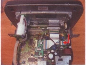
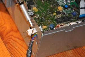
|[[File:W220_CT90-MC04_install_9.jpg|thumb|none|Unplug the revealed brown flat cable ('''do not use the force - push up the clip which tightens the cable''') and the indicated white flat cable.]] | |||
|} | |||
{| | |||
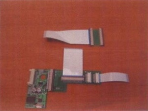
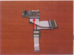
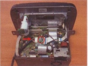
|[[File:W220_CT90-MC04_install_10.jpg|thumb|none|Assemble the supplied PCBs and flat cables as shown.]] | |||
|[[File:W220_CT90-MC04_install_11.jpg|thumb|none|Connect the 2 PCBs together with the flat cable as shown.]] | |||
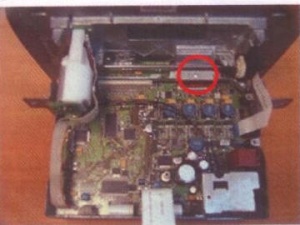
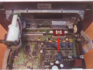
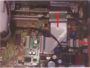
|[[File:W220_CT90-MC04_install_12.jpg|thumb|none|Connect the inserted flat cables to the head unit and the original brown cable to the PCB.]] | |||
|} | |||
{| | |||
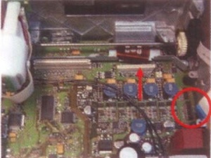
|[[File:W220_CT90-MC04_install_13.jpg|thumb|none|Connect the original flat cable to PCB.]] | |||
|[[File:W220_CT90-MC04_install_14.jpg|thumb|none|Connect the RGB cable to the PCB. The PCB should be located with the hole over a resistor.]] | |||
|[[File:W220_CT90-MC04_install_15.jpg|thumb|none|Reassemble the head unit.]] | |||
|} | |||
{| | |||
|[[File:W220_CT90-MC04_install_16.jpg|thumb|none|Leave the RGB cable outside to connect to the interface.]] | |||
|[[File:W220_CT90-MC04_RGB_cable_installation.jpg|thumb|none|To pull the RGB cable through the hole in COMAND case the wires must be disconnected from the connector.]] | |||
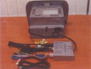
|[[File:W220_CT90-MC04_install_17.jpg|thumb|none|Reassembled head unit.]] | |||
|} | |||
With all connections made, securely mount the interface module and head unit back into the vehicle. | |||
== Operation == | |||
{| | |||
|[[File:W220_CT90-MC04_operation_NAV_button.jpg|thumb|none|Operate by NAV button.]] | |||
|[[File:W220_CT90-MC04_Remote_Control.jpg|thumb|none|Operate using remote control.]] | |||
|} | |||
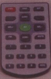
Test the unit; the 'NAV' button should now switch through the AV sources. Use the remote control to adjust pictures: | |||
* PWR: Power. | |||
* AV: Switch between: AV1/AV2/V3/RGB/MMI. | |||
* OSD: Function key to setup program and adjust picture. | |||
* SEL+/SEL-: Move between main menu and sub menu. | |||
* CON+/CON-: Select menu and change picture values. | |||
== Audio == | == Audio == | ||
Revision as of 19:24, 26 December 2015
See page 69 on http://issuu.com/talkaudio/docs/connects2_catalogue_2009__all_products_

Video input interface for Mercedes S-Class W220 '04-'05 / CL-Class C216 '06>. This interface allows additional video inputs to the original COMAND screen; 2 Video inputs / Automatically switchable camera input / RGB Navigation input. There are also 2 video outputs and an audio output. Selection can be made by infra-red remote control or by the NAV button in the vehicle. The Remote control can also be used to adjust the picture via an on screen menu. If a camera and reverse signal wire are connected it will automatically switch when the vehicle is put into reverse gear.
The head unit shown in the installation instructions is taken from a 2006 Mercedes S-Class W220 LHD. The modification of the monitor unit will be similar in the CL-Class. During the installation it is advised that the keys are removed from the ignition, until all components are reconnected.
Disclaimer: Please observe the law in the country where this product is installed. It may be illegal for TV/DVD pictures to be in view of the driver whilst the vehicle is moving.
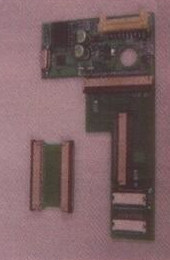
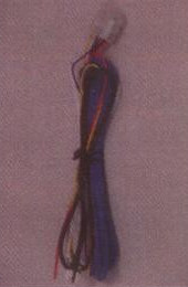
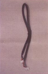
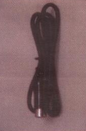
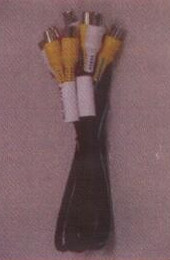
Kit Contents
 |
 |
 |
 |
 |
 |
 |
 |
 |
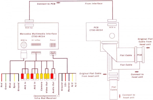
Interface Connections
Installation
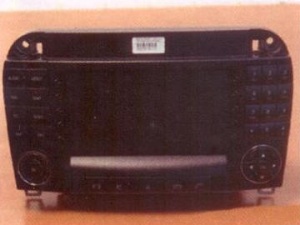 |
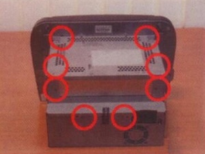 |
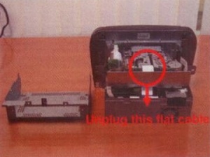 |
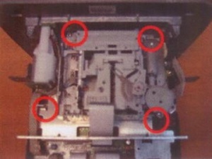 |
 |
 |
 |
 |
 |
 |
 |
 |
With all connections made, securely mount the interface module and head unit back into the vehicle.
Operation
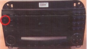 |
 |
Test the unit; the 'NAV' button should now switch through the AV sources. Use the remote control to adjust pictures:
- PWR: Power.
- AV: Switch between: AV1/AV2/V3/RGB/MMI.
- OSD: Function key to setup program and adjust picture.
- SEL+/SEL-: Move between main menu and sub menu.
- CON+/CON-: Select menu and change picture values.
Audio
The kit supports video input only. To input the audio an FM transmitter or modulator will be required. The interface will act as an audio switch. The output will repeat AV1 or AV2, depending on which picture is selected.
