Exterior mirrors: Difference between revisions
(memory function) |
|||
| Line 337: | Line 337: | ||
(CAN message from the left front SAM control module (N10/6)) | (CAN message from the left front SAM control module (N10/6)) | ||
and the dew point (CAN message from automatic A/C pushbutton control module (N22)). | and the dew point (CAN message from automatic A/C pushbutton control module (N22)). | ||
== Memory function == | |||
<!-- GF91.29-P-0001S | |||
Memory switch function, MODELS 215, 220 (except , 220.063), | |||
MODEL 220.063 with CODE (275a) Memory package (driver's seat, steering column, mirrors) | |||
16.4.98 | |||
--> | |||
The settings for the left and right exterior mirrors, the interior | |||
rearview mirror and the steering column are also stored together | |||
with the driver's seat setting. | |||
'''Up to 31.05.01''' | |||
* Driver's side: For each transmitter key, ''two'' complete seat settings can be stored and called up again on the driver's side. A total of eight memory areas are available. | |||
* Front passenger's side: On the front passenger's side, ''two'' complete seat settings can be stored and called up again. | |||
'''As of 01.06.01''' | |||
* Driver's side: For each transmitter key, ''three'' complete seat settings can now be stored and called up again on the driver's side. A total of twelve memory areas are available. | |||
* Front passenger's side: On the front passenger's side, three complete seat settings can now be stored and called up again. | |||
* Rear (only model 220 with electrically adjustable individual rear seats): Three complete seat settings can be stored and called up again. | |||
=== Calling up stored positions function === | |||
<!-- GF91.29-P-2011S | |||
Calling up stored positions, function | |||
MODELS 215, 220 (except , 220.063) | |||
MODEL 220.063 with CODE (275a) Memory package (driver's seat, steering column, mirrors) | |||
29.4.98 | |||
--> | |||
Calling up stored positions (driver, front passenger) | |||
{| | |||
|[[File:W220_Calling_up_stored_positions_function.png]] | |||
| | |||
* 1 - CAN message: "Current storage block" (depends on ignition/starter key) | |||
* 2 - Actuation of the respective motors | |||
* 3 - Feedback of the current position | |||
* A67 - Inside mirror unit | |||
* K40/6 - Left front fuse and relay module | |||
* K40/6kD - Relay 1 Jacket tube longitudinal adjustment | |||
* K40/6kE - Relay 2 Jacket tube longitudinal adjustment | |||
* K40/6kI - Relay 1 Jacket tube height adjustment | |||
* K40/6kI - Relay 1 Jacket tube height adjustment | |||
* K40/6kJ - Relay 2 Jacket tube height adjustment | |||
* M20 - ESC [ELV] motor | |||
* M21/1 - Left electrically adjustable and heated exterior mirror | |||
* M21/2 - Right electrically adjustable and heated exterior mirror | |||
* M27 - Left front seat adjustment motor group with memory | |||
* M28 - Right front seat adjustment motor group with memory | |||
* N10/6 - Left front SAM control module | |||
* N10/6 - Left front SAM control module | |||
* N32/1 - Left front seat adjustment control module with memory | |||
* N32/2 - Right front seat adjustment control module with memory | |||
* N69/1 - Left front [[door control module]] | |||
* N69/2 - Right front [[door control module]] | |||
* N70 - Overhead control panel control module | |||
* N73 - EIS control module | |||
* S50/1 - Outside mirror switch with mirror fold-in/fold-out facility | |||
|} | |||
Function requirements: | |||
* No overvoltage or undervoltage | |||
* Term.15R or 15 ON | |||
* Driver's door/front passenger's door open | |||
* No button for manual seat adjustment, mirror adjustment or steering column adjustment pressed | |||
* Normalization carried out properly | |||
'''Calling up memory and Ergo positions (driver) up to 31.5.01.''' | |||
When calling up the memory function or Ergo function by pressing | |||
the memory 1 switch (N69/1s6), memory 2 switch (N69/1s7) or | |||
ERGONOMICS switch (N69/1s8) in the left [[door control module]] | |||
(N69/1) the positions stored in the relevant control modules are actuated: | |||
* Inside rearview mirror | |||
* Front passenger's exterior mirror | |||
* Steering column | |||
* Driver seat | |||
The left front door control module (N69/1) recognizes that a switch | |||
is pressed and sends the following message via the CAN: | |||
"Left front memory - Assume position 1/2/Ergo". | |||
Memory 3 (N69/1s15), in the left front door control module (N69/1). | |||
This message is received from the left front SAM control module (N10/6), | |||
from the overhead control panel control module (N70), | |||
from the right front door control module (N69/2) and from the left | |||
front seat adjustment control module with memory (N32/1). | |||
Consequently these control modules, and also the left front [[door | |||
control module]] (N69/1), actuate the respective motors (see Figure), | |||
when the button is pressed further, until it is recognized via the | |||
local position recognitions that the stored positions are reached. | |||
'''As of 1.6.01 the Ergo position is not used anymore, it is | |||
replaced by a further memory button.''' | |||
This memory location is called up by pressing the switch for | |||
memory 3 (N69/1s9) in the left front door control module (N69/1). | |||
'''Calling up memory/Ergo positions (front passenger) up to 31.5.01.''' | |||
When the memory feature is called up by pressing the memory 1 switch (N69/2s6), | |||
memory 2 switch (N69/2s7) ERGONOMY switch (N69/2s9) in the right front [[door control module]] (N69/2), | |||
the positions of the front passenger's seat stored in the right front seat | |||
adjustment control module with memory (N32/2) are approached. | |||
The right front door control module (N69/2) recognizes that a | |||
switch is pressed and places the following message on the CAN: | |||
"Right front memory - Assume position 1/2/Ergo". This message is | |||
received from right front seat adjustment control module with | |||
memory (N32/2) which then, when the button is pressed further, | |||
actuates the motors of the right front seat adjustment motor group with memory (M28) | |||
until it is recognized via local position recognitions that the stored positions are reached. | |||
'''As of 1.6.01 the Ergo position is not used anymore, it is | |||
replaced by a further memory button.''' | |||
This memory location is called up by pressing the memory 3 switch | |||
(N69/2s15) in the right front control module (N69/2). | |||
'''Calling up memory positions (rear).''' | |||
(On model 220 with electrically adjustable individual rear seats with | |||
memory) | |||
Left rear side: | |||
When the memory feature is called up by pressing the memory 1 | |||
switch (N69/3s3) or memory 2 switch (N69/4s4) or memory 3 | |||
switch(N69/3s5) in the driver's side [[door control module]] (N69/3) | |||
the positions of the left rear seat stored in the rear seats control | |||
module (N25/6) are approached. | |||
Right rear side: | |||
When the memory feature is called up by pressing the memory 1 | |||
switch (N69/4s3) or memory 2 switch (N69/3s4) or memory 3 | |||
switch (N69/4s5) in the right rear [[door control module]] (N69/4) | |||
the respective door control module recognizes that a switch is | |||
pressed and places the following message on the CAN "Left and right rear memory - Assume position 1/2/3". | |||
This message is received by the rear seats control module (N25/6) | |||
which then, if the button is pressed further, actuates the respective | |||
adjustment motors until it is recognized via local position | |||
recognitions that the stored positions are reached. | |||
===Storing memory positions function=== | |||
<!-- GF91.29-P-2012S | |||
Storing memory positions, function | |||
MODEL 215.###, 220.### (except , 220.063) 1# | |||
MODEL 220.063 1# with CODE (275a) Memory package (driver's seat, steering column, mirrors) | |||
29.4.98 | |||
--> | |||
Function prerequisites: | |||
* Circuit 15R or 15 ON | |||
Together with the storage of the driver's seat position in addition | |||
the inside rearview mirror, the outside mirror as well as the | |||
steering column position are stored in the relevant control module key-related. | |||
'''Memory locations up to 31.5.01.''' | |||
The positions of the driver's seat and front passenger's seat | |||
including the adjustments of the multicontour backrest (special | |||
equipment) can be stored on ''two'' memory locations. | |||
'''Memory locations as of 1.6.01''' | |||
The positions of the driver's seat and front passenger's seat | |||
including the adjustments of the multicontour backrest (special equipment) | |||
can be stored on ''three'' memory locations. | |||
The positions are stored in the following control modules: | |||
Driver side: | |||
* Seat position: Left front seat adjustment control module with memory (N32/1) | |||
* Inside rearview mirror position: Overhead control panel control module (N70) | |||
* Left outside mirror: Left front [[door control module]] (N69/1) | |||
* Right outside mirror: Right front [[door control module]] (N69/2) | |||
* Steering column position: Left front SAM control module (N10/6) | |||
Passenger side: | |||
* Seat position: Right front seat adjustment control module with memory (N32/2) | |||
Rear seats (model 220 with electrically adjustable individual rear seats only): | |||
* Seat position: Rear seats control module (N25/6) | |||
'''Up to 31.5.01 storing driver's seat position with associated mirror and steering column positions.''' | |||
The currently adjusted positions are stored by pressing the | |||
memory switch (N69/1s9) in the left front [[door control module]] | |||
(N69/1) and then within 3 seconds, the memory 1 switch (N69/1s6) | |||
or memory 2 switch (N69/1s7). | |||
If at the same time no other switch in this switch group is pressed, | |||
the left front [[door control module]] (N69/1) sends a message to the | |||
CAN. The respective control modules receive this request for | |||
position storage and check whether valid values are supplied via | |||
local position measurements. | |||
If this is the case, the current positions are stored in the non-volatile memory. | |||
'''Up to 31.5.01 storing front passenger's seat position.''' | |||
The currently adjusted front passenger's seat position is stored in | |||
the same way as the driver's seat position. | |||
It is triggered by pressing the memory switch (N69/2s9) in the right | |||
front door control module (N69/2) and then, within 3 seconds, | |||
memory 1 switch (N69/2s6) or memory 2 switch (N69/2s7) | |||
'''Storing left rear seat position''' | |||
(model 220 with electrically adjustable individual rear seats only). | |||
The currently adjusted rear seat position is stored by pressing the | |||
memory switch (N69/3s10) in the left rear door control module | |||
(N69/3) and then memory switch 1 within 3 seconds (N69/3s3) or | |||
memory 2 switch (N69/3s4) or memory 3 switch (N69/3s5). | |||
The storage process for the right rear side is analog to the left | |||
rear side. In the process the memory switch (N69/4s10) in the right | |||
rear door control module (N69/4) and memory 1 switch (N69/4s3) | |||
or memory 2 switch (N69/4s4) or memory 3 switch (N69/4s5) are | |||
used. | |||
'''As of 1.6.01 revised storage process.''' | |||
There are two ways of storing the respective positions: | |||
For the driver's side: | |||
a) If the memory switch (N69/1s9) is kept pressed and | |||
additionally one of the memory 1 switches (N69/1s6), | |||
memory 2 switches (N69/1s7); memory 3 switches | |||
(N69/1s15) is pressed for t>=40 ms, the storage process is | |||
thereby concluded. | |||
b) Press the memory switch (N69/1s9) for t=>40 ms and then | |||
release again, then within t<3 seconds, press the desired | |||
memory location via memory 1 switch (N69/1s6); memory 2 | |||
switch (N69/1s7), memory 3 switch (N69/1s15) for t>=40 ms | |||
so that the storage process is concluded. | |||
In order to avoid faults during storage it is necessary that the | |||
voltage supply is applied to the control module for a further | |||
five seconds at least. | |||
If during the storage process no other switch from the switch | |||
group is pressed, the values are sent from the respective door | |||
control module to the relevant control modules via the CAN. | |||
These control modules check whether the local position | |||
measurement supplies valid values. If this is the case the current | |||
positions are stored in the non-volatile memory. | |||
The storage process for the front passenger's side is analog to | |||
the driver's side. In the process the memory 1 switch (N69/2s6), | |||
memory 2 switch (N69/2s7), memory 3 switch (N69/2s15) and | |||
memory switch (N69/2s9) are used. | |||
===Code-related storage block selection=== | |||
<!-- GF91.29-P-3004S, Code-related storage block selection | |||
MODELS 215, 220 (except , 220.063) | |||
MODEL 220.063 with CODE (275a) Memory package (driver's seat, steering column, mirrors) | |||
25.5.98 | |||
--> | |||
The driver's seat position (memory feature) is stored in the left | |||
front seat adjustment control module with memory (N32/1) (vehicle | |||
with right hand steering (N32/2)) on a key-related basis. | |||
The electronic ignition switch control module (N73) recognizes the | |||
inserted transmitter key (A8/1) and notifies the left front seat | |||
adjustment control module with memory (N32/1) (vehicles with right | |||
hand steering: right front seat adjustment control module with | |||
memory (N32/2)) which of the four memory blocks are to be | |||
activated via the CAN. | |||
One memory block consists of two memory areas. One complete | |||
seat position can be stored for each memory area. The memory | |||
area is selected via the memory 1 switch (N69/1s6)/memory 2 | |||
switch (N69/1s7) | |||
in the left front door control module (N69/1) (vehicle with right hand | |||
steering: Corresponding switches in the right front door control | |||
module (N69/2)). | |||
{| class="wikitable" | |||
! Key track | |||
! 1 | |||
! 2 | |||
! 5/6 | |||
! 3/4/7/8 | |||
|- | |||
|Memory block number (CAN message from electronic ignition switch) | |||
|1 | |||
|2 | |||
|3 | |||
|4 | |||
|- | |||
|- | |||
|Position key on left front [[door control module]] (N69/1) | |||
|1 2 | |||
|1 2 | |||
|1 2 | |||
|1 2 | |||
|- | |||
|Memory area in the left front seat adjustment control module with memory (N32/1) (LHS) | |||
|1 2 | |||
|3 4 | |||
|5 6 | |||
|7 8 | |||
|} | |||
Revision as of 22:00, 13 February 2017
Facelift
Parts
 |
 |
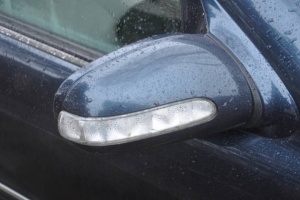
Outside rearview mirror
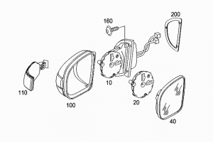
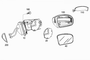
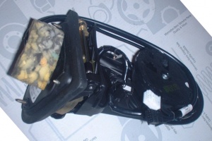
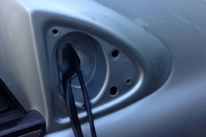
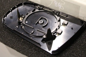
Part number A2208100576 (left) and A2208100876 (right). The part comes without glass and cover as shown in the picture below. The part is attached to front door using 3 A0029843729 (M4X22) bolts.
 |
 |
Mirror cover
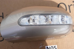
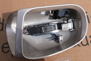
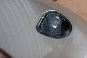
Part number for mirror cover is A2208100964 (left) and A2208101064 (right). The part comes without turn signal light module.
 |
 |
 |
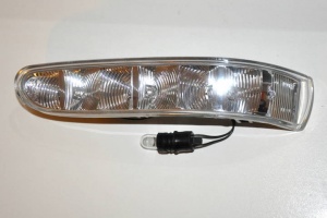
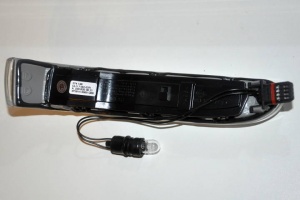
Turn signal light
Turn signal light (blinker lamp) has part number A2208200521 (left) and A2208200621 (right).
For the vanity light bulb there is LED upgrade available.
 |
 |
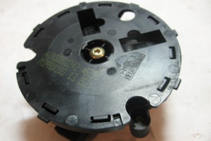
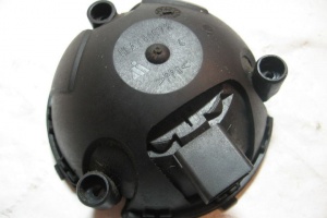
Adjustment motor
Electronic adjustment motor A2038202242 is used on both sides.
 |
 |
 |
| Error Code | Generated By | Description |
|---|---|---|
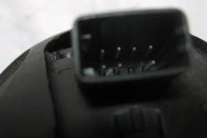
| B1208 | DCM-FL - Door control module front left | The signal from component M21/1r3 (Mirror in/out adjustment potentiometer) is faulty. |
Seals
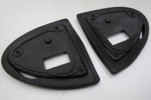
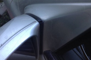
Mirror seals (gaskets) have part number A2208110198 (left) and A2208110298 (right).
 |
 |
Glass
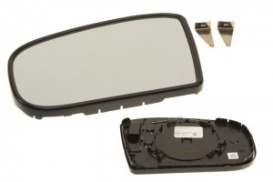
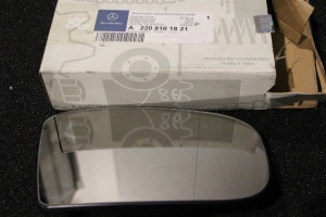
Original mirror glass is expensive high theft risk part (especially driver's side mirror for option code 249 - INSIDE AND OUTSIDE MIRROR AUTOMATIC DIMMING).
Aftermarket mirrors with heating are available in ebay for as cheap as 15 EUR.
 |
 |
 |
DIY
Pre-facelift
DIY
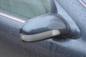
- Remove the mirror cover by pressing in a small spring clip at the top.
- Release the mirror housing cover by also pressing in a spring clip near the outer edge.
Driver-side exterior rearview mirror automatic dimming feature
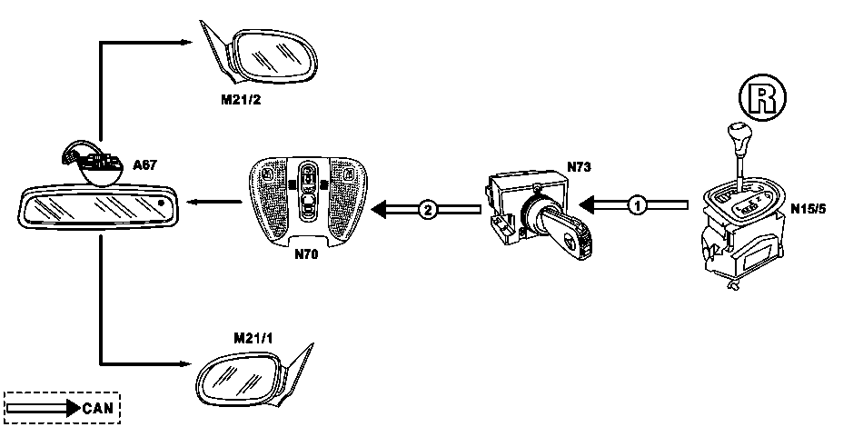
The inside rearview mirror (A67) in combination with the overhead control panel control module (N70) serves as master for dimming the electrically adjustable and heated left outside mirror (M21/1) (special equipment).
Function prerequisites:
- Voltage not too low or too high
- C.15R or C.15 ON
The light reaching the surface of the mirror is reflected to a greater or lesser extent depending on the magnitude of the control voltage. The control voltage is regulated by the interior rearview mirror unit (A67) (master) and the overhead control panel control module (N70). Two discrete leads are connected to the left front door control module (N69/1) for this purpose (vehicles with right-hand steering: right front door control module ((N69/2)).
Regulation is accomplished depending on the ambient light and the light reaching the mirror. These two variables are measured by the ambient light sensor (A67h2) in the interior rearview mirror housing (rear) and the automatic dimming interior rearview mirror sensor (A67h1) in the mirror glass in the interior rearview mirror unit.
If one of the interior lights is switched on or the CAN message "Reverse gear engaged" is received from the electronic ignition/ starter switch control module (N73), the exterior rearview mirror as well as interior rearview mirror become brighter.
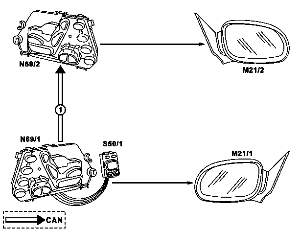
Adjust left/right exterior mirror function
(Shown on LHS vehicle)
|
|
Function requirements:
- no overvoltage/undervoltage
- Term.15R or 15 ON
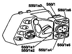
The left and right exterior mirrors can be electrically adjusted via the switches in the switch train for exterior mirror adjustment with fold in/out function (S50/1) in the front left door control module (N69/1) (RHS vehicle: Front right door control module (N69/2)). The following settings are possible:
- Horizontal mirror glass adjustment
- Vertical mirror glass adjustment
- Mirror housing folding-in (garage position) and folding-out (driving position)
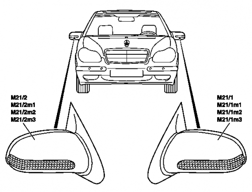
The adjustments are carried out by the motors in the left electrically adjustable and heated exterior mirror (M21/1) and the right electrically adjustable and heated exterior mirror (M21/2). The motors are actuated via the front left door control module (N69/1) and the front right door control module (N69/2).
The memory function (special equipment) can be used to call up stored mirror settings. Setting the parking position of the exterior mirror on the front passenger's side enables the driver to check the distance of the relevant rear wheel from the edge of the curb when reversing into a parking space.
Fold in left/right exterior mirror function
The left and right exterior mirror housings can be electrically folded in and out. Via the switches in the switch train for exterior mirror adjustment with fold in/out function (S50/1) in the front left door control module (N69/1) (RHS vehicle: Front right door control module (N69/2) ), the left/right exterior mirror housing can be moved to the garage position (mirror housings folded in) or the driving position (mirror housings folded out). The switch statuses of the switches for folding the exterior mirror in (S50/1s4) and the switches for folding the exterior mirror out (S50/1s5) are read in by the front left [[door control module]] (N69/1) (RHS vehicle: Front right door control module (N69/2)) inserted and placed onto the CAN as a message for the door control module on the front passenger's side.
The front left door control module (N69/1) and the front right door control module (N69/2) then actuate the motor for folding the mirror in (M21/1m3) and the motor for folding the mirror in (M21/2m3) in the left and right exterior mirror housings.
Up to 31.05.01 the fold in exterior mirror switch (S50/1s4) or the fold out exterior mirror switch (S50/1s5) must be actuated until the mirror housings are in the desired position.
As of 01.06.01 the fold in exterior mirror switch (S50/1s4) or the fold out exterior mirror switch (S50/1s5) merely have to be touched, and the mirror housings are automatically moved to the desired position.
Exterior rearview mirror adjustment switch
The switches for adjusting the exterior rearview mirrors are located in a separate assembly in the exterior mirror adjustment switch with mirror fold-in/out (S50/1) on the left front door control module (N69/1) (vehicles with right-hand steering : right front door control module (N69/2)).
Left front door control module (N69/1) (left-hand steering)
The left and right exterior rearview mirror glass can be adjusted in the vertical and horizontal directions with the exterior mirror up/down adjustment switch (S50/1s1) and exterior mirror in/out adjustment switch (S50/1s2). The switch can be set to the exterior rearview mirror to be adjusted with the
All switches for adjusting the exterior rearview mirrors are located in the exterior rearview mirror switch group with fold-in/out feature (S50/1). This switch group is connected to the door control module on the driver's side by a discrete wiring harness.
The switching status of the switches for adjustment of the exterior rearview mirrors is read in by the door control module on the driver's side evaluated and transferred to the CAN bus as a message.
Exterior rearview mirror adjustment motor
The motors for adjusting the mirror glass and housing are located in the left electrically adjustable and heated exterior rearview mirror (M21/1)/right electrically adjustable and heated exterior rearview mirror (M21/2).
The left exterior rearview mirror glass can be adjusted vertically and horizontally with the vertical mirror adjustment motor (up/down) (M21/1m1) and horizontal mirror adjustment motor (in/out) (M21/1m2) in the left electrically adjustable and heated exterior rearview mirror (M21/1). The right exterior rearview mirror glass can be adjusted vertically and horizontally with the vertical mirror adjustment motor (up/down) (M21/2m1) and horizontal mirror adjustment motor (in/out) (M21/2m2) in the right electrically adjustable and heated exterior rearview mirror (M21/2). The housing of the left/right exterior rearview mirror can be folded in (garage position) and out (driving position) with the mirror fold-in motors (M21/1m3)/(M21/2m3).
The motors are DC motors. Two potentiometers each are located on the motor shafts (M21/1m1)/(M21/2m1) and (M21/1m2)/(M21/2m2) for position recognition. The motors for outside rearview mirror (with fold-in/out feature) (M21/1m3)/(M21/2m3) are not equipped with a position recognition feature.
The motors turn to the left or right depending on the polarity of the actuating voltage. Actuation is accomplished by the left front door control module (N69/1)/right front door control module (N69/2).
Exterior rearview mirror position measurement function
A potentiometer for measuring the position is located on each of the shafts for the vertical mirror adjustment motors (up/down) (M21/1m1)/(M21/2m1) and horizontal mirror adjustment motors (in/out) (M21/1m2)/(M21/2m2) in the left and right exterior mirrors.
Heating left/right exterior rearview mirrors function
Function prerequisites:
- Voltage not too low or too high
- C.61 ON
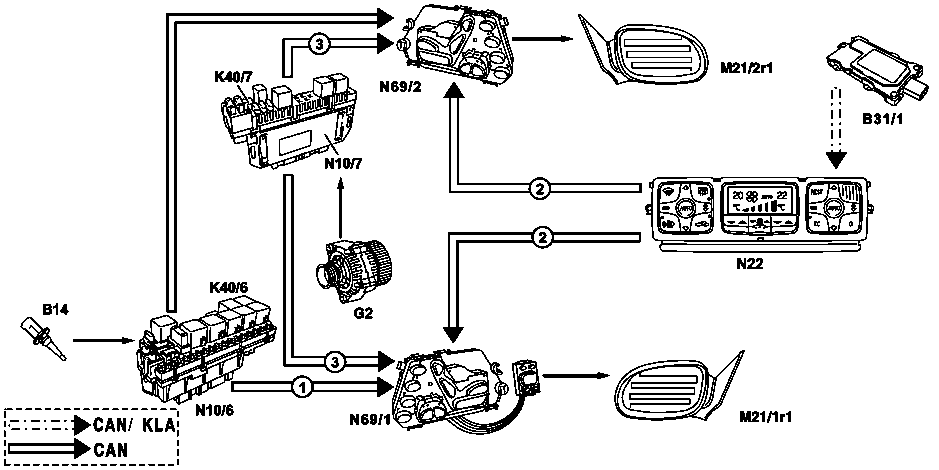
The left mirror heater (M21/1r1) in the left electrically adjustable and heated exterior rearview mirror (M21/1) and the right mirror heater (M21/1r1) in the right electrically adjustable and heated exterior rearview mirror (M21/2) consist of a heater resistor connected in series with a PTC resistor. The heater resistor is located on the rear of the mirror glass to which it is permanently bonded. The power supply and regulated switching on and switching off of the heater resistors is accomplished by the left front door control module (N69/1)/right front door control module (N69/2). The mirror heater is controlled in relation to the outside air temperature (CAN message from the left front SAM control module (N10/6)) and the dew point (CAN message from automatic A/C pushbutton control module (N22)).
Memory function
The settings for the left and right exterior mirrors, the interior rearview mirror and the steering column are also stored together with the driver's seat setting.
Up to 31.05.01
- Driver's side: For each transmitter key, two complete seat settings can be stored and called up again on the driver's side. A total of eight memory areas are available.
- Front passenger's side: On the front passenger's side, two complete seat settings can be stored and called up again.
As of 01.06.01
- Driver's side: For each transmitter key, three complete seat settings can now be stored and called up again on the driver's side. A total of twelve memory areas are available.
- Front passenger's side: On the front passenger's side, three complete seat settings can now be stored and called up again.
- Rear (only model 220 with electrically adjustable individual rear seats): Three complete seat settings can be stored and called up again.
Calling up stored positions function
Calling up stored positions (driver, front passenger)
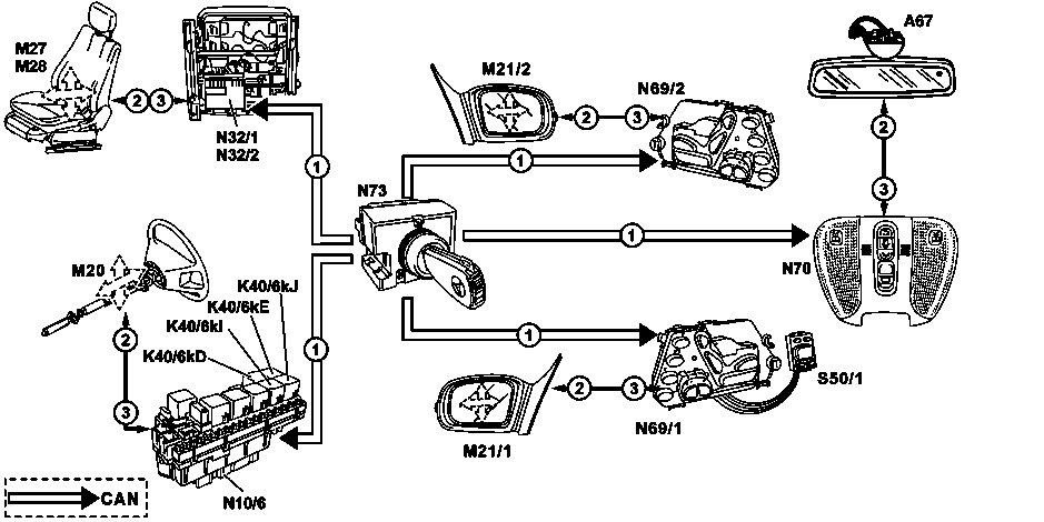
|
|
Function requirements:
- No overvoltage or undervoltage
- Term.15R or 15 ON
- Driver's door/front passenger's door open
- No button for manual seat adjustment, mirror adjustment or steering column adjustment pressed
- Normalization carried out properly
Calling up memory and Ergo positions (driver) up to 31.5.01. When calling up the memory function or Ergo function by pressing the memory 1 switch (N69/1s6), memory 2 switch (N69/1s7) or ERGONOMICS switch (N69/1s8) in the left door control module (N69/1) the positions stored in the relevant control modules are actuated:
- Inside rearview mirror
- Front passenger's exterior mirror
- Steering column
- Driver seat
The left front door control module (N69/1) recognizes that a switch is pressed and sends the following message via the CAN: "Left front memory - Assume position 1/2/Ergo". Memory 3 (N69/1s15), in the left front door control module (N69/1).
This message is received from the left front SAM control module (N10/6), from the overhead control panel control module (N70), from the right front door control module (N69/2) and from the left front seat adjustment control module with memory (N32/1).
Consequently these control modules, and also the left front [[door control module]] (N69/1), actuate the respective motors (see Figure), when the button is pressed further, until it is recognized via the local position recognitions that the stored positions are reached.
As of 1.6.01 the Ergo position is not used anymore, it is replaced by a further memory button. This memory location is called up by pressing the switch for memory 3 (N69/1s9) in the left front door control module (N69/1).
Calling up memory/Ergo positions (front passenger) up to 31.5.01. When the memory feature is called up by pressing the memory 1 switch (N69/2s6), memory 2 switch (N69/2s7) ERGONOMY switch (N69/2s9) in the right front door control module (N69/2), the positions of the front passenger's seat stored in the right front seat adjustment control module with memory (N32/2) are approached. The right front door control module (N69/2) recognizes that a switch is pressed and places the following message on the CAN: "Right front memory - Assume position 1/2/Ergo". This message is received from right front seat adjustment control module with memory (N32/2) which then, when the button is pressed further, actuates the motors of the right front seat adjustment motor group with memory (M28) until it is recognized via local position recognitions that the stored positions are reached.
As of 1.6.01 the Ergo position is not used anymore, it is replaced by a further memory button. This memory location is called up by pressing the memory 3 switch (N69/2s15) in the right front control module (N69/2).
Calling up memory positions (rear). (On model 220 with electrically adjustable individual rear seats with memory)
Left rear side: When the memory feature is called up by pressing the memory 1 switch (N69/3s3) or memory 2 switch (N69/4s4) or memory 3 switch(N69/3s5) in the driver's side door control module (N69/3) the positions of the left rear seat stored in the rear seats control module (N25/6) are approached.
Right rear side: When the memory feature is called up by pressing the memory 1 switch (N69/4s3) or memory 2 switch (N69/3s4) or memory 3 switch (N69/4s5) in the right rear door control module (N69/4) the respective door control module recognizes that a switch is pressed and places the following message on the CAN "Left and right rear memory - Assume position 1/2/3". This message is received by the rear seats control module (N25/6) which then, if the button is pressed further, actuates the respective adjustment motors until it is recognized via local position recognitions that the stored positions are reached.
Storing memory positions function
Function prerequisites:
- Circuit 15R or 15 ON
Together with the storage of the driver's seat position in addition the inside rearview mirror, the outside mirror as well as the steering column position are stored in the relevant control module key-related.
Memory locations up to 31.5.01. The positions of the driver's seat and front passenger's seat including the adjustments of the multicontour backrest (special equipment) can be stored on two memory locations.
Memory locations as of 1.6.01 The positions of the driver's seat and front passenger's seat including the adjustments of the multicontour backrest (special equipment) can be stored on three memory locations.
The positions are stored in the following control modules:
Driver side:
- Seat position: Left front seat adjustment control module with memory (N32/1)
- Inside rearview mirror position: Overhead control panel control module (N70)
- Left outside mirror: Left front door control module (N69/1)
- Right outside mirror: Right front door control module (N69/2)
- Steering column position: Left front SAM control module (N10/6)
Passenger side:
- Seat position: Right front seat adjustment control module with memory (N32/2)
Rear seats (model 220 with electrically adjustable individual rear seats only):
- Seat position: Rear seats control module (N25/6)
Up to 31.5.01 storing driver's seat position with associated mirror and steering column positions. The currently adjusted positions are stored by pressing the memory switch (N69/1s9) in the left front door control module (N69/1) and then within 3 seconds, the memory 1 switch (N69/1s6) or memory 2 switch (N69/1s7).
If at the same time no other switch in this switch group is pressed, the left front door control module (N69/1) sends a message to the CAN. The respective control modules receive this request for position storage and check whether valid values are supplied via local position measurements. If this is the case, the current positions are stored in the non-volatile memory.
Up to 31.5.01 storing front passenger's seat position. The currently adjusted front passenger's seat position is stored in the same way as the driver's seat position. It is triggered by pressing the memory switch (N69/2s9) in the right front door control module (N69/2) and then, within 3 seconds, memory 1 switch (N69/2s6) or memory 2 switch (N69/2s7)
Storing left rear seat position (model 220 with electrically adjustable individual rear seats only). The currently adjusted rear seat position is stored by pressing the memory switch (N69/3s10) in the left rear door control module (N69/3) and then memory switch 1 within 3 seconds (N69/3s3) or memory 2 switch (N69/3s4) or memory 3 switch (N69/3s5).
The storage process for the right rear side is analog to the left rear side. In the process the memory switch (N69/4s10) in the right rear door control module (N69/4) and memory 1 switch (N69/4s3) or memory 2 switch (N69/4s4) or memory 3 switch (N69/4s5) are used.
As of 1.6.01 revised storage process. There are two ways of storing the respective positions:
For the driver's side: a) If the memory switch (N69/1s9) is kept pressed and additionally one of the memory 1 switches (N69/1s6), memory 2 switches (N69/1s7); memory 3 switches (N69/1s15) is pressed for t>=40 ms, the storage process is thereby concluded.
b) Press the memory switch (N69/1s9) for t=>40 ms and then release again, then within t<3 seconds, press the desired memory location via memory 1 switch (N69/1s6); memory 2 switch (N69/1s7), memory 3 switch (N69/1s15) for t>=40 ms so that the storage process is concluded.
In order to avoid faults during storage it is necessary that the voltage supply is applied to the control module for a further five seconds at least.
If during the storage process no other switch from the switch group is pressed, the values are sent from the respective door control module to the relevant control modules via the CAN. These control modules check whether the local position measurement supplies valid values. If this is the case the current positions are stored in the non-volatile memory.
The storage process for the front passenger's side is analog to the driver's side. In the process the memory 1 switch (N69/2s6), memory 2 switch (N69/2s7), memory 3 switch (N69/2s15) and memory switch (N69/2s9) are used.
The driver's seat position (memory feature) is stored in the left front seat adjustment control module with memory (N32/1) (vehicle with right hand steering (N32/2)) on a key-related basis.
The electronic ignition switch control module (N73) recognizes the inserted transmitter key (A8/1) and notifies the left front seat adjustment control module with memory (N32/1) (vehicles with right hand steering: right front seat adjustment control module with memory (N32/2)) which of the four memory blocks are to be activated via the CAN. One memory block consists of two memory areas. One complete seat position can be stored for each memory area. The memory area is selected via the memory 1 switch (N69/1s6)/memory 2 switch (N69/1s7) in the left front door control module (N69/1) (vehicle with right hand steering: Corresponding switches in the right front door control module (N69/2)).
| Key track | 1 | 2 | 5/6 | 3/4/7/8 |
|---|---|---|---|---|
| Memory block number (CAN message from electronic ignition switch) | 1 | 2 | 3 | 4 |
| Position key on left front door control module (N69/1) | 1 2 | 1 2 | 1 2 | 1 2 |
| Memory area in the left front seat adjustment control module with memory (N32/1) (LHS) | 1 2 | 3 4 | 5 6 | 7 8 |
