Starter: Difference between revisions
Jump to navigation
Jump to search
(parts) |
|||
| Line 24: | Line 24: | ||
== Remove starter, install == | == Remove starter, install == | ||
The complexity of starter removal depends on model (see below for more details): | |||
* In case of [[4Matic]] complete exhaust system has to be removed. | |||
* In case of S400 CDI/S600/S65L AMG right catalytic converter has to be removed. | |||
* In case of S600/S600 PULLMAN front right exhaust system has to be removed. | |||
* In case of S280/S320/S320 CDI/S350/S430/S500 starter can be removed without major problems. | |||
=== S280/S320/S350/S430/S500/S500 PULLMAN === | |||
<!-- AR15.30-P-7100I | <!-- AR15.30-P-7100I | ||
Remove starter, install | Remove starter, install | ||
| Line 38: | Line 45: | ||
* ENGINE 112.944 in MODEL 220.065/165 ([[S320]], except [[S320]] CDI) | * ENGINE 112.944 in MODEL 220.065/165 ([[S320]], except [[S320]] CDI) | ||
* ENGINE 113.941 in MODEL 220.070/170 ([[S430]], except [[S430]] [[4Matic]]) | * ENGINE 113.941 in MODEL 220.070/170 ([[S430]], except [[S430]] [[4Matic]]) | ||
* ENGINE 113.960 in MODEL 220.075/175/875 ([[S500]], except [[S500]] [[4Matic]]) | * ENGINE 113.960 in MODEL 220.075/175/875 ([[S500]]/S500 PULLMAN, except [[S500]] [[4Matic]]) | ||
* ENGINE 112.972 in MODEL 220.067/167 ([[S350]], except [[S350]] [[4Matic]]) | * ENGINE 112.972 in MODEL 220.067/167 ([[S350]], except [[S350]] [[4Matic]]) | ||
| Line 68: | Line 75: | ||
* Bolt of starter to crankcase - Nm 42. | * Bolt of starter to crankcase - Nm 42. | ||
=== Removal/installation on S350 === | ==== Removal/installation on S350 ==== | ||
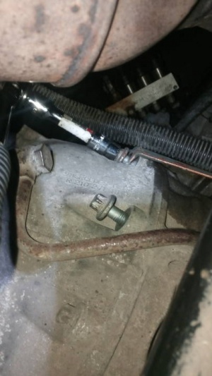
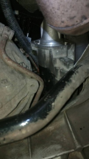
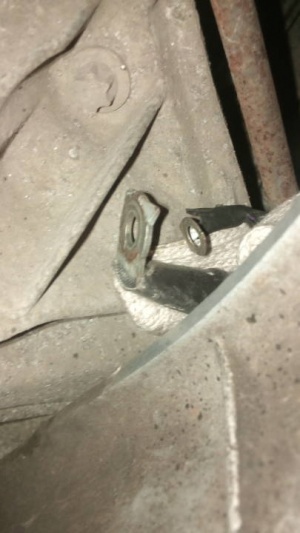
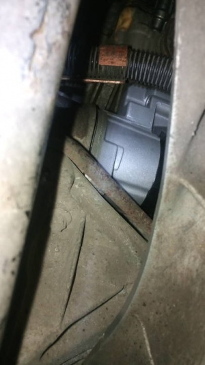
Starter is attached to transmission and crankcase with two E14 torx bolts. | Starter is attached to transmission and crankcase with two E14 torx bolts. | ||
| Line 88: | Line 95: | ||
|[[File:W220_new_starter_installed_look_through_other_hole.jpg|thumb|none|New starter installed (look through other hole).]] | |[[File:W220_new_starter_installed_look_through_other_hole.jpg|thumb|none|New starter installed (look through other hole).]] | ||
|} | |} | ||
=== S600/S65 AMG === | |||
<!-- AR15.30-P-7100H, Remove/install starter, | |||
ENGINES 275 in MODEL 215, 220, 230 | |||
ENGINES 285 in MODEL 240 | |||
30.10.08 | |||
--> | |||
Valid for: | |||
* ENGINE 275 in MODEL 220 ([[S600]]/[[S65 AMG]]) | |||
{| | |||
|[[File:W220_remove_install_starter_S600_1.jpg]] | |||
| | |||
* 1 - Screw | |||
* 2 - Screw | |||
* 3 - Screw | |||
* 4 - Screw | |||
* 5 - Heat shield | |||
* 8 - Three way catalytic converter bracket | |||
|} | |||
{| | |||
|[[File:W220_remove_install_starter_S600_2.jpg]] | |||
| | |||
* 3 - Screw | |||
* 6 - Contact protection | |||
* 7 - Electric line circuit 30 | |||
* 8 - Three way catalytic converter bracket | |||
* 9 - Electric cable circuit 50 | |||
* M1 - Starter | |||
|} | |||
Removing: | |||
# Detach ground line from battery | |||
# '''Remove right catalytic converter''' | |||
# Remove bolts (1, 2) | |||
# Loosen bolt (3) | |||
# Remove bolt (4) and remove heat shield (5) | |||
# Detach protection against accidental contact (6) and detach electrical line circuit 30 (7). | |||
# Detach electrical line circuit 50 (9) | |||
# Remove bolt (3) and remove catalytic converter (8) | |||
# Remove starter (M1) from below | |||
# When replacing the starter (M1) check ring gear on drive plate for wear and damage. Rotate engine at crankshaft in direction of rotation. | |||
Install: | |||
# Position starter (M1) at crankcase | |||
# Loosely position bolt (3) with catalytic converter bracket (8) | |||
# Connect electrical line circuit 50 (9) | |||
# Connect electrical line circuit 30 (7) and attach protection against accidental contact (6) | |||
# Loosely position bolts (1,2) on the heat shield (5). Pay attention to cable clamp at bolt (1). | |||
# Loosely position bolt (4). Pay attention to heat shield (5). | |||
# Tighten bolts (3, 4) | |||
# Tighten bolts (1, 2) for heat shield (5) | |||
# Install right three way catalytic converter. | |||
# Connect ground cable to battery | |||
# Carry out function check | |||
# Perform basic programming | |||
# Read out fault memory and erase. When the work is complete stored faults must be worked on in the diagnostic trouble code memories and erased. Connect STAR DIAGNOSIS and read out fault memory. | |||
Torque specifications: | |||
* Nut, connection for circuit 30: 14 Nm | |||
* Nut, connection for circuit 50: 6 Nm | |||
* Bolt connecting starter to crankcase: 42 Nm | |||
* Bolt, heat shield to crankcase: 8 Nm | |||
===S600/S600 PULLMAN=== | |||
<!-- AR15.30-P-7100N, Remove starter, install, | |||
ENGINE 137.970 in MODEL 215.378, 220.178 /878 | |||
3.2.09 | |||
--> | |||
Valid for: | |||
* ENGINE 137.970 in MODEL 220.178/878 ([[S600]]/[[S600 PULLMAN]]) | |||
{| | |||
|[[File:W220_remove_starter_install_S600_PULLMAN.jpg]] | |||
| | |||
* 1 - Active body control hydraulic line | |||
* 2 - Bolts | |||
* 3 - Nuts | |||
* 4 - Electric cable circuit 30 | |||
* 5 - Electric cable circuit 50 | |||
* M1 - Starter | |||
|} | |||
# Dismount ground line to the battery | |||
# Detach lower engine compartment paneling | |||
# '''Remove front right exhaust system''' | |||
# Unscrew bolts of Active Body Control hydraulic line (1) | |||
# Unscrew bolts (2) of starter | |||
# Unscrew nuts (3) and remove electrical lines (4, 5) | |||
# Take starter (M1) down and out | |||
# When replacing the starter (M1) check ring gear on drive plate for wear and damage. Rotate engine at crankshaft in direction of rotation. | |||
# Install in the reverse order | |||
# Perform function check | |||
# Render electrical system operational. Perform basic programming. | |||
# Read out fault memory and erase. When the work is complete stored faults must be worked on in the diagnostic trouble code memories and erased. Connect STAR DIAGNOSIS and read out fault memory. | |||
Torqure specifications: | |||
* Nut, connection for circuit 30: 14 Nm | |||
* Nut, connection for circuit 50: 6 Nm | |||
* Bolt of starter to crankcase: 42 Nm | |||
===4Matic (S350/S430/S500)=== | |||
<!-- | |||
AR15.30-P-7100PW, Remove/install starter | |||
ENGINE 112 in MODEL 203.084, 211.082, 220.087, 203.284, 211.080, 203.281 /081, 211.280, 220.187, 211.282 | |||
ENGINE 113 in MODELS 220.184 /183, 211.283, 220.083 /084, 211.083 | |||
ENGINE 272 in MODELS 211.087 /092 /287 /292 | |||
ENGINE 273 in MODELS 211.090 /290 | |||
13.4.06 | |||
--> | |||
Valid for: | |||
* ENGINE 112 in MODEL 220.087/187 ([[S350]] [[4Matic]]) | |||
* ENGINE 113 in MODEL 220.083/183 ([[S430]] [[4Matic]]), 220.084/184 ([[S500]] [[4Matic]]) | |||
{| | |||
|[[File:W220_remove_install_starter_4matic_1.jpg]] | |||
| | |||
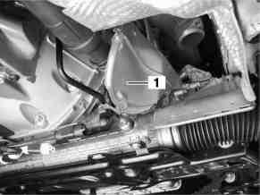
* 1 - Exhaust shielding plate for propeller shaft of front axle gear | |||
|} | |||
{| | |||
|[[File:W220_remove_install_starter_4matic_2.jpg]] | |||
| | |||
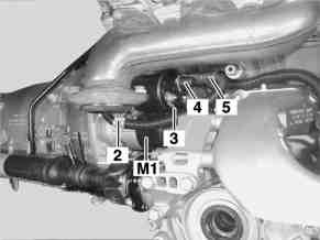
* 2 - Mounting clip | |||
* 3 - Electric cable circuit 30 | |||
* 4 - Cap | |||
* 5 - Electric cable circuit 50 | |||
|} | |||
{| | |||
|[[File:W220_remove_install_starter_4matic_3.jpg]] | |||
| | |||
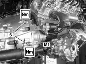
* 6 - Bolts | |||
* M1 - Starter | |||
|} | |||
# Disconnect ground line from battery | |||
# Detach lower engine compartment paneling | |||
# '''Remove complete exhaust system''' | |||
# Detach heat shield to steering gear | |||
# Dismount exhaust shielding plate (1) for propeller shaft front axle gear | |||
# Detach mounting clamp (2) of electrical line circuit 50 (5) at choke housing | |||
# Detach cap (4) from electrical line circuit 50 (5) | |||
# Unscrew nut of electrical line circuit 50 (5) at starter (M1) | |||
# Unscrew nut of electrical line circuit 30 (3) at starter (M1) | |||
# Remove bolts (6) | |||
# Remove starter (M1) from the rear via the rack-and-pinion steering | |||
# Check ring gear on drive plate for wear and damage. Only when replacing starter. Rotate engine at crankshaft in the direction of rotation of engine. | |||
# Install in the reverse order | |||
# Carry out function check | |||
# Perform basic programming | |||
# Read out fault memory and erase. When the work is complete stored faults must be worked on in the diagnostic trouble code memories and erased. Connect STAR DIAGNOSIS and read out fault memory. | |||
Torqure specifications: | |||
* Nut, connection for circuit 30: 14 Nm | |||
* Nut, connection for circuit 50: 6 Nm | |||
* Bolt connecting starter to crankcase: 42 Nm | |||
== Starter relay == | == Starter relay == | ||
Revision as of 21:33, 22 February 2017
Back to Index
Parts
| Part No. | Notes |
|---|---|
| A0061510501 | For S350. From Date: 30/10/2003. Voltage: 12V, Kilowatt: 1.4kW, Rotation: CW, Teeth: 10T. Borg & Beck part number: BST2087. Bosch part numbers: 0986021280, 0001108404, 0001108403. |
| A0051516501 | For S350. To Date: 30/10/2003. Voltage: 12V, Kilowatt: 1.4kW, Rotation: CW, Teeth: 10T. Bosch part numbers: 0986019507, 0986019500, 0001108197. |
| A0061510601 | For S430/S500. From Date: 30/10/2003. Voltage: 12V, Kilowatt: 1.7kW, Rotation: CW, Teeth: 10T. Bosch part numbers: 0986021290, 0001108213. |
| A1121510001 | For S430/S500. To Date: 30/10/2003. Voltage: 12V, Kilowatt: 1.7kW, Rotation: CW, Teeth: 10T. Bosch part numbers: 0001115005, 0001115004, 0001108213, BX1789, 0986017890. |
| N910105010044 | Bolt M10X90. Starter to crankcase and transmission. |
Remove starter, install
The complexity of starter removal depends on model (see below for more details):
- In case of 4Matic complete exhaust system has to be removed.
- In case of S400 CDI/S600/S65L AMG right catalytic converter has to be removed.
- In case of S600/S600 PULLMAN front right exhaust system has to be removed.
- In case of S280/S320/S320 CDI/S350/S430/S500 starter can be removed without major problems.
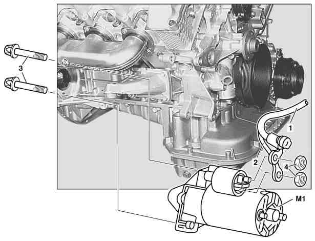
S280/S320/S350/S430/S500/S500 PULLMAN
Valid for:
- ENGINE 112.922 in MODEL 220.063 (S280)
- ENGINE 112.944 in MODEL 220.065/165 (S320, except S320 CDI)
- ENGINE 113.941 in MODEL 220.070/170 (S430, except S430 4Matic)
- ENGINE 113.960 in MODEL 220.075/175/875 (S500/S500 PULLMAN, except S500 4Matic)
- ENGINE 112.972 in MODEL 220.067/167 (S350, except S350 4Matic)
|
|
- Turn key in electronic ignition lock EIS into position "0". Key cannot be withdrawn.
- Dismount ground line to the battery.
- Detach lower engine compartment paneling.
- Unscrew bolts (3)
- Unscrew nuts (4) and remove electrical lines (1, 2).
- Take starter (M1) down and out
- When replacing the starter check ring gear on the drive plate for wear and damage. Rotate engine at the crankshaft in direction of rotation.
- Install in the reverse order
- Render electrical system operational
- Read diagnostic trouble code memory and erase
Torque specification:
- Nut of connection of circuit 30 - Nm 14.
- Nut of connection circuit 50 - Nm 6.
- Bolt of starter to crankcase - Nm 42.
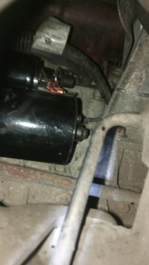
Removal/installation on S350
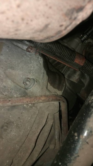
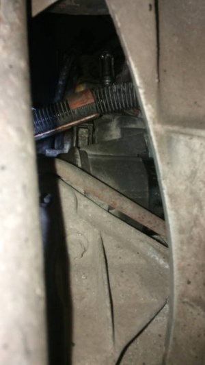
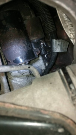
Starter is attached to transmission and crankcase with two E14 torx bolts. Starter can be removed from underneath the vehicle - only plastic shields have to be removed. Since there is not much space the process is not very convenient but is possible.
 |
 |
 |
 |
 |
 |
 |
 |
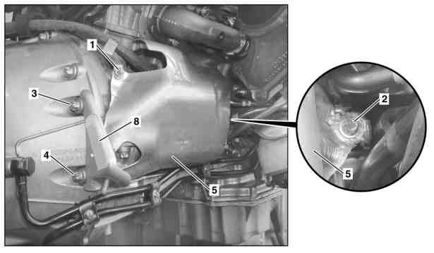
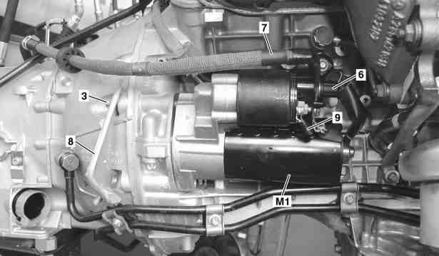
S600/S65 AMG
Valid for:
|
|
|
|
Removing:
- Detach ground line from battery
- Remove right catalytic converter
- Remove bolts (1, 2)
- Loosen bolt (3)
- Remove bolt (4) and remove heat shield (5)
- Detach protection against accidental contact (6) and detach electrical line circuit 30 (7).
- Detach electrical line circuit 50 (9)
- Remove bolt (3) and remove catalytic converter (8)
- Remove starter (M1) from below
- When replacing the starter (M1) check ring gear on drive plate for wear and damage. Rotate engine at crankshaft in direction of rotation.
Install:
- Position starter (M1) at crankcase
- Loosely position bolt (3) with catalytic converter bracket (8)
- Connect electrical line circuit 50 (9)
- Connect electrical line circuit 30 (7) and attach protection against accidental contact (6)
- Loosely position bolts (1,2) on the heat shield (5). Pay attention to cable clamp at bolt (1).
- Loosely position bolt (4). Pay attention to heat shield (5).
- Tighten bolts (3, 4)
- Tighten bolts (1, 2) for heat shield (5)
- Install right three way catalytic converter.
- Connect ground cable to battery
- Carry out function check
- Perform basic programming
- Read out fault memory and erase. When the work is complete stored faults must be worked on in the diagnostic trouble code memories and erased. Connect STAR DIAGNOSIS and read out fault memory.
Torque specifications:
- Nut, connection for circuit 30: 14 Nm
- Nut, connection for circuit 50: 6 Nm
- Bolt connecting starter to crankcase: 42 Nm
- Bolt, heat shield to crankcase: 8 Nm
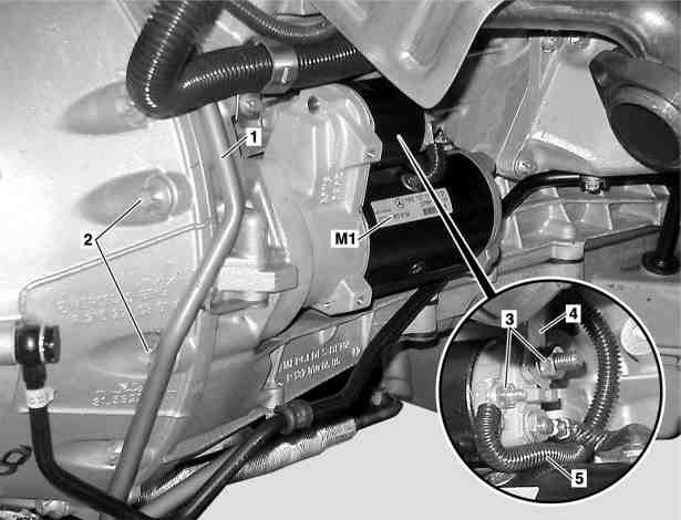
S600/S600 PULLMAN
Valid for:
- ENGINE 137.970 in MODEL 220.178/878 (S600/S600 PULLMAN)
|
|
- Dismount ground line to the battery
- Detach lower engine compartment paneling
- Remove front right exhaust system
- Unscrew bolts of Active Body Control hydraulic line (1)
- Unscrew bolts (2) of starter
- Unscrew nuts (3) and remove electrical lines (4, 5)
- Take starter (M1) down and out
- When replacing the starter (M1) check ring gear on drive plate for wear and damage. Rotate engine at crankshaft in direction of rotation.
- Install in the reverse order
- Perform function check
- Render electrical system operational. Perform basic programming.
- Read out fault memory and erase. When the work is complete stored faults must be worked on in the diagnostic trouble code memories and erased. Connect STAR DIAGNOSIS and read out fault memory.
Torqure specifications:
- Nut, connection for circuit 30: 14 Nm
- Nut, connection for circuit 50: 6 Nm
- Bolt of starter to crankcase: 42 Nm
4Matic (S350/S430/S500)
Valid for:
- ENGINE 112 in MODEL 220.087/187 (S350 4Matic)
- ENGINE 113 in MODEL 220.083/183 (S430 4Matic), 220.084/184 (S500 4Matic)
|
|
|
|
|
|
- Disconnect ground line from battery
- Detach lower engine compartment paneling
- Remove complete exhaust system
- Detach heat shield to steering gear
- Dismount exhaust shielding plate (1) for propeller shaft front axle gear
- Detach mounting clamp (2) of electrical line circuit 50 (5) at choke housing
- Detach cap (4) from electrical line circuit 50 (5)
- Unscrew nut of electrical line circuit 50 (5) at starter (M1)
- Unscrew nut of electrical line circuit 30 (3) at starter (M1)
- Remove bolts (6)
- Remove starter (M1) from the rear via the rack-and-pinion steering
- Check ring gear on drive plate for wear and damage. Only when replacing starter. Rotate engine at crankshaft in the direction of rotation of engine.
- Install in the reverse order
- Carry out function check
- Perform basic programming
- Read out fault memory and erase. When the work is complete stored faults must be worked on in the diagnostic trouble code memories and erased. Connect STAR DIAGNOSIS and read out fault memory.
Torqure specifications:
- Nut, connection for circuit 30: 14 Nm
- Nut, connection for circuit 50: 6 Nm
- Bolt connecting starter to crankcase: 42 Nm