Front doors: Difference between revisions
Jump to navigation
Jump to search
(added instructions) |
|||
| Line 114: | Line 114: | ||
# Remove door liner on front door | # Remove door liner on front door | ||
# Remove crank operated window on front door | # Remove crank operated window on front door | ||
# Unhook Bowden cable (1) for inside door opener onto door lock (6) and remove. Unclip holder (8) on lock. Open retainer (4) for unlocking bar (3). | # Unhook Bowden cable (1) for inside door opener onto door lock (6) and remove. Unclip holder (8) on lock. | ||
# Open retainer (4) for unlocking bar (3). | |||
# Press IRCL line (5) off door lock IRCL element | # Press IRCL line (5) off door lock IRCL element | ||
# Drill out blind rivets (arrows). Use 4.8 mm dia. drill for drilling out, taking care not to damage the inner door panel. Drive out remains of rivets with suitable drift. Remove remains of rivets and swarf from door, danger of rusting. | # Drill out blind rivets (arrows). Use 4.8 mm dia. drill for drilling out, taking care not to damage the inner door panel. Drive out remains of rivets with suitable drift. Remove remains of rivets and swarf from door, danger of rusting. | ||
Revision as of 11:09, 7 August 2017
Remove/install door lining on front door
Shown on model 220 up to VIN 316716 (pre-facelift):
Shown on model 220 up to VIN 316716 (pre-facelift):

|
|
Shown on model 220 As of VIN 316717 (facelift):

|
|
Shown on model 220 up to VIN 316716 (pre-facelift):
|
|
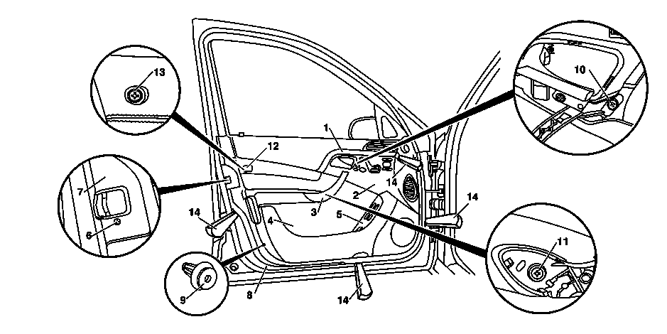
- Press trim strip (1) out of covering (2)
- Up to VIN 316716 (pre-facelift):
- Remove door handle cover (3) from door handle
- Unclip cap (17)
- As of VIN 316717 (facelift):
- Remove door opener cover (16)
- Remove screws (15)
- Press covering (2) off of door lining (2)
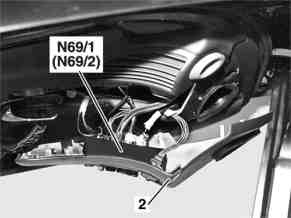
- Disconnect electrical connector from left front door control unit (N69/1) and right front door control unit (N69/2). For this purpose, remove covering (2).
- Unclip cover on switch group (5) with switch group from door lining (4). For this purpose, pull cover on switch group (5) downward at bottom edge until cover on switch group (5) can be removed.
- Unscrew bolt (6) from round cover plate (7). For this purpose, remove round cover plate (7).
- Unscrew bolts (10, 11) from inner door handle
- Remove screw (13). For this purpose, remove cover (12).
- Press door lining (4) off of inner door panel (8). Move mounting wedge (14) directly to fastening clips (9) and ensure that the retainer tabs on the fastening clip (9) do not tear out of the door lining (4).
- Lift door lining (4) at top on sealing rail out of retaining clips and simultaneously pull away from inner door panel (8). Installation: Remove fastening clips remaining on inner door panel (8) and install.
- Unhook Bowden cable from inside door opener
- Disconnect electrical connectors from door lining (4) and lay down door lining (4)
- Check door foil and fastening clips (9). Installation: Replace damaged door foil and fastening clips (9).
- Install in the reverse order
Removing and installing front door lock
|
|
|
|
Removing:
- Remove door liner on front door
- Remove crank operated window on front door
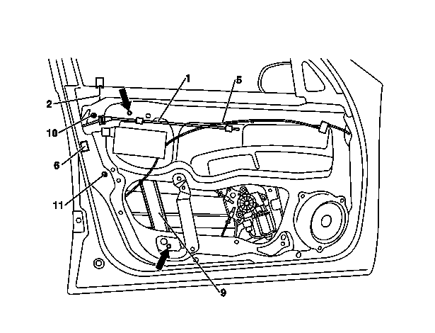
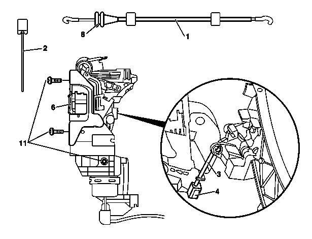
- Unhook Bowden cable (1) for inside door opener onto door lock (6) and remove. Unclip holder (8) on lock.
- Open retainer (4) for unlocking bar (3).
- Press IRCL line (5) off door lock IRCL element
- Drill out blind rivets (arrows). Use 4.8 mm dia. drill for drilling out, taking care not to damage the inner door panel. Drive out remains of rivets with suitable drift. Remove remains of rivets and swarf from door, danger of rusting.
- Unhook window lift guide rail (9) from inner door panel and push to one side
- Unscrew lock fixing screws (11)
- Unscrew lock cover screw (10). Lock cover is permanently attached to the door lock and cannot be removed separately.
- Remove door lock (6) via access cover
Installing:
- Insert door lock (6) via access cover
- Screw in lock fixing screws (11)
- Screw in and tighten screw (10) for lock cover
- Hook window lift guide rail (9) onto inner door panel with the two mounting hooks
- Rivet window lift guide rail (9) flush with inner door panel with 4.8 mm blind rivets (arrows)
- Connect central locking line (5) to central locking element on door lock
- Close retainer (4) for unlocking bar (3). With retainer (4) open, push unlocking bar upwards until resistance can be felt. Then close retainer again
- Hang Bowden cable (1) onto door lock (6). Clip holder (8) to door lock.
- Install crank window
- Adjust crank window on front door
- Check clearance and correct if necessary
- Carry out operational check
- Fix sound deadener to inner door panel
- Install door liner on front door
- Screw on door lock: 10 Nm
- Front door test values: Clearance: 2(+-1)mm
Removing and installing exterior door handle on front door
|
|
|
Removal:
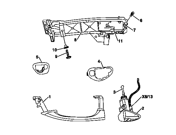
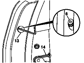
- Remove cap from installation opening (13) narrow side of door
- Unscrew Torx screw (6). Remove Torx screw (6). Secure against falling down.
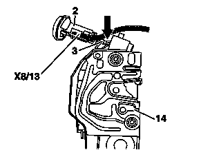
- Remove guide (2). Slightly pivot guide (2) toward rear and then pull out toward outside. Simultaneously pull out handle (1) slightly. Avoid damaging paint.
- Disconnect driver's door infrared receiver connector (X8/13)
- Remove handle (1) with bases (4) and (5). Pull handle (1) with bases (4) and (5) out of hinge strap (8) toward rear.
- Remove door liner
- Pull off insulating mat in area of door lock
- Remove hinge strap (8). First open retainer for release handle, unscrew screw (9) from handle recess and remove hinge strap (8) with release handle through installation opening in inner door panel.
Installation:
- Install hinge strap (8). Insert hinge strap (8) with release handle through installation opening in inner door panel and insert release handle into control lever retainer. Turn screw (9) into handle recess.
- Install handle (1) in hinge strap (8) together with bases (4) and (5). Ensure that the lever on the handle slides behind the actuation lever (11) on the bracket so that the lock can be unlocked.
- Insert guide (2). Simultaneously insert driver's door infrared receiver connector (X8/13). When inserting the guide (2) ensure that the rotating rod (3) is moved into the door lock (14) in the correct position.
- Tighten guide with Torx screw (6). Secure Torx screw (6) against falling down.
- Adjust clearance between handle (1) and actuation lever (12). Press release handle with retainer opened up until resistance can be felt. Then lock retainer.
- Check clearance. Pull handle (1) until resistance can be felt clearly.
- Glue on insulating mat. Replace damaged insulating mat.
- Install door liner
- Insert installation opening (13) cap into narrow side of door
- Check for proper function
- Screw for front door handle: 3 Nm
- Adjustment values for side door: Clearance: 2(+-1)mm
Removing and installing exterior door handle on front door (KEYLESS-GO)

|

|
|
|
|
Removal:
- Remove cap from installation opening (13) narrow side of door
- Unscrew Torx screw (6). Remove Torx screw (6). Secure against falling down.
- Remove guide (2). Slightly pivot guide (2) toward rear and then pull out toward outside. Simultaneously pull out handle (1) slightly. Avoid damaging paint.
- Disconnect driver's door infrared receiver connector (X8/13)
- Remove door liner
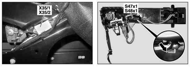
- Disconnect keyless go connector on hinge strap (8)
- Remove handle (1) with bases (4) and (5). Pull handle (1) with bases (4) and (5) out of hinge strap (8) toward rear.
- Pull off insulating mat in area of door lock
- Remove hinge strap (8). First open retainer for release handle, unscrew screw (9) from handle recess and remove hinge strap (8) with release handle through installation opening in inner door panel.
- Disconnect keyless go connector on inner door panel. Remove cable strap.
Installation:
- Install hinge strap (8). Insert hinge strap (8) with release handle through installation opening in inner door panel and insert release handle into control lever retainer. Turn screw (9) into handle recess.
- Contact keyless go connector on inner door panel. Replace cable strap.
- Install handle (1) in hinge strap (8) together with bases (4) and (5). Ensure that the lever on the handle slides behind the actuation lever (11) on the bracket so that the lock can be unlocked.
- Contact keyless go connector on bearing bracket (8)
- Insert guide (2). Simultaneously insert driver's door infrared receiver connector (X8/13). When inserting the guide (2) ensure that the rotating rod (3) is moved into the door lock (14) in the correct position.
- Tighten guide with Torx screw (6). Secure Torx screw (6) against falling down.
- Adjust clearance between handle (1) and actuation lever (12). Press release handle with retainer opened up until resistance can be felt. Then lock retainer.
- Check clearance. Pull handle (1) until resistance can be felt clearly.
- Glue on insulating mat. Replace damaged insulating mat.
- Install door liner
- Insert installation opening (13) cap into narrow side of door
- Check for proper function
- Screw for front door handle: 3 Nm
- Adjustment values for side door: Clearance: 2(+-1)mm
Door Handle Latch Mechanism
Issues
- Inner handle is too loose and will not pull the latch mechanism far enough forward to release the latch.
- There is no tension adjustment for the cable.
- The cable slips out of the guide very easily as you move the inner door cover away from the door.
- A common fault is improper positioning of the cable in the inner handle mechanism.
Solution
At the back of the door handle mechanism there is a "Guide" - the inner part of the cable must be threaded into the guide (1 in the photo), and the cable jacket fitted into a small receptacle (at 2).

With that done, the cable is positioned properly, the tension is correct, the door handle operates the latch, and springs back to the proper position when released.
Reference: http://www.benzworld.org/forums/w220-s-class/1593251-skylaw-2.html#post4776376
