Front seats: Difference between revisions
No edit summary |
mNo edit summary |
||
| Line 1: | Line 1: | ||
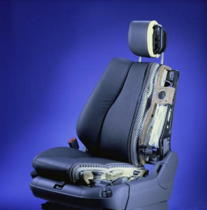
[[File:W220_prefacelift_front_seat_crosscut.jpg|thumb|none|[[Facelift] front seat (crosscut).]] | [[File:W220_prefacelift_front_seat_crosscut.jpg|thumb|none|[[Facelift]] front seat (crosscut).]] | ||
== Front seat adjustment == | == Front seat adjustment == | ||
Revision as of 21:27, 29 August 2017
Front seat adjustment
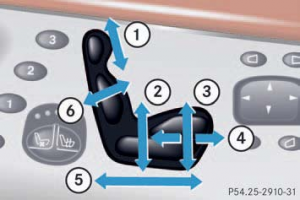
The seat adjustment switches are located on the front doors.
- (1) Head restraint height
- (2) Seat height
- (3) Seat cushion tilt
- (4) Seat cushion depth
- (5) Seat fore and aft adjustment
- (6) Seat backrest tilt
To adjust the seat switch on ignition or open the respective door.
Seat fore and aft adjustment: Press the switch forward or backward in the direction of arrow (5). Adjust seat to a comfortable seating position that still allows you to reach the accelerator/brake pedal safely. The position should be as far to the rear as possible, consistent with ability to properly operate controls.
Seat cushion tilt: Press the switch up or down in the direction of arrow (3) until your upper legs are lightly supported.
Seat cushion depth: Press the switch forward or backward in the direction of arrow (4) until your legs are supported comfortably.
Seat backrest tilt: Press the switch forward or backward in the direction of arrow (6) until your arms are slightly angled when holding the steering wheel.
Seat height: Press the switch up or down in the direction of arrow (2).
Head restraint height: Press the switch up or down in the direction of arrow (1).
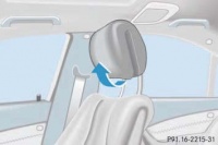
Head restraint tilt: Manually adjust the angle of the head restraint. Push or pull on the lower edge of the head restraint cushion.
Unoccupied front passenger seat automatic adjusting: The feature below is deactivated at the factory. If you wish to have it activated, use DAS. The front passenger seat head restraint automatically lowers after a few seconds when the front passenger seat is not occupied. This improves the driver's outward view as well as the forward view from the rear passenger compartment. When the front passenger seat is occupied again, the front passenger seat head restraint returns to the last set position within a few seconds. If the front passenger seat was moved fore or aft while not being occupied, the front passenger seat head restraint returns to a position that corresponds best with the seat’s axial position when the seat is occupied again.
Remove/install front seat backrest seat-back lining
|
|
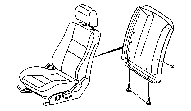
- Slide the front seat forwards with the longitudinal adjustment mechanism
- Slide backrest forwards with the inclination adjustment mechanism
- Unscrew screws (1)
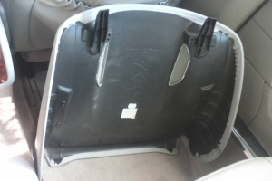
- Pull seat-back lining (2) down and take off. Installation: slide seat-back lining into top of backrest.
- Install in the reverse order
 |
 |
 |
Remove and install headrest guide on front seat
|
|
Remove:
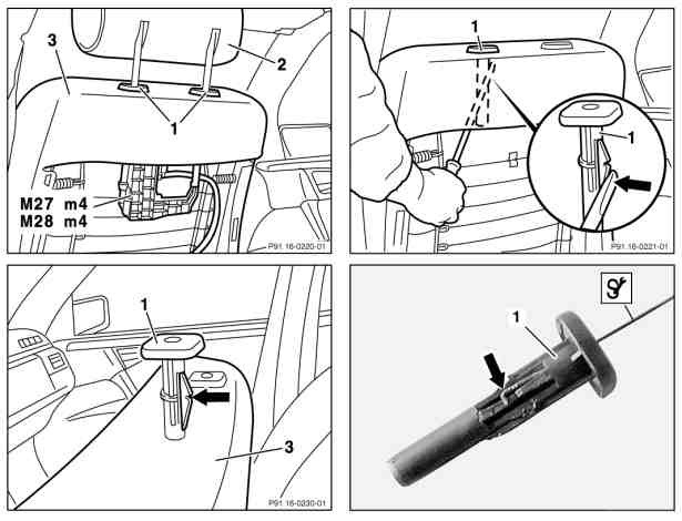
- Remove head restraint (2)
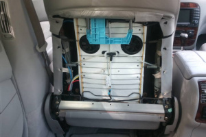
- Remove tensioning element (seat-back lining) from front seat backrest
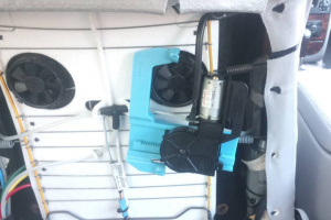
- Remove head restraint raise/lower motor (M27m4/M28m4). Push motor to right first and then remove downwards.
- Release catch at head restraint guide (1) using screwdriver. Push back catch (arrow) at head restraint guide (1) using screwdriver and pull head restraint (1) out upwards.
- Release catch at head restraint guide (1) using pulling hook. Insert pulling hook into top of head restraint guide (1), push back catch and pull out head restraint upwards.
Install:
- Insert head restraint guide (1) into backrest frame of front seat backrest (3). Do not damage backrest upholstery. Catch (arrow) must point towards rear.
- Engage head restraint guide (1) in backrest frame of front seat backrest (3)
- Install head restraint raise/lower motor (M27m4/M28m4). Insert motor facing upwards and then push to left until it engages in backrest frame.
- Fit seat-back lining to front seat backrest (3)
- Install head restraint (2)
| Error Code | Generated By | Description |
|---|---|---|
| B1203 | ESA-FL - Electronic seat adjustment front left | Hall sensor of component M27m4 (Head restraint raise/lower motor) is faulty |
Facelift head restraint motor A2209700026 fits both sides.
Note: when installing new motor the new motor may be need to be moved manually to the position of the old motor, otherwise it may be encountered that motor is not able to move the full distance.
Remove/install front seat (as of 01/09/2002)
- Switch off ignition, remove ignition key (vehicles without KEYLESS-GO, code 889).
- Switch off engine, remove transmitter key from vehicle (with KEYLESS-GO, code 889). Keep transmitter key out of transmitter range.
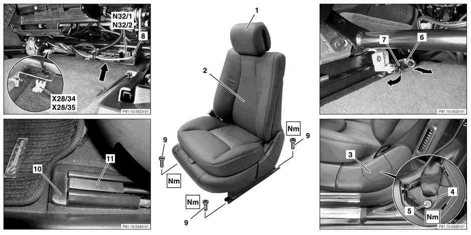
- Remove head restraint (1)
- Adjust front seat (2) to front. Move front and rear seat cushions all the way up. Move backrest into upright position.
- Remove cover (3) at rear side paneling
- Remove screw/bolt (5) at belt end fitting (4). Installation: When screwing on, ensure that belt end fitting (4) remains mobile.
- Remove rear screws/bolts (9) from seat rails. Remove cover (11) from seat rail.
- Turn retaining clamp (7) at Bowden cable in direction of transmission tunnel and remove
- Unhook grommet (6) with Bowden cable from bracket
- Position front seat (2) to rear
- Remove front screw/bolt (9) from seat rails. Remove cover (11) from seat rail.
- Pry off pneumatic line plug coupling (8) with open end wrench, size 7. Slightly incline seat toward rear in vehicle.
- Detach connecting coupling (see arrow) from front seat adjustment control unit with memory, left (N32/1), right (N32/2). Slightly incline seat toward rear in vehicle.
- Disconnect 2-pin driver seat connecting point buckle emergency tensioning retractor connector (X28/34), 2-pin front passenger seat connecting point buckle emergency tensioning retractor connector (X28/35). Slightly incline seat toward rear in vehicle.
- Remove seat rail final cover (10) from seat rails
- Lift front seat (2) and remove
- Install in the reverse order
- Check function of seat adjustment mechanism
Torque specifications:
- Bolt to seat runner: 45 Nm
- Screw on belt end fitting: 30 Nm
Remove/install front seat (up to 31/08/2002)
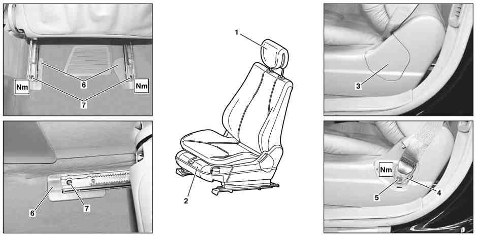
|
|
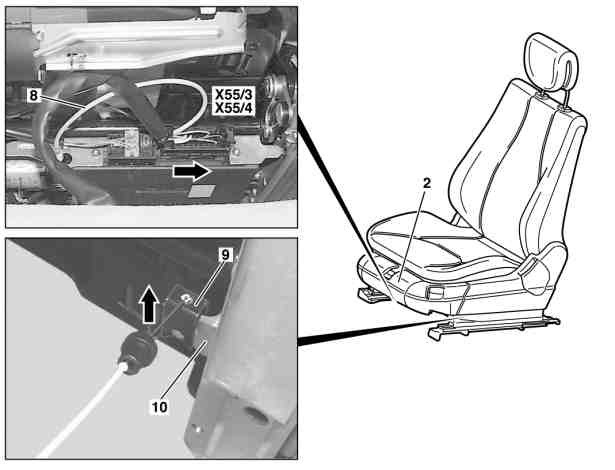
|
|
- Remove head restraint (1)
- Adjust front seat (2) to front
- Remove cover (3) above belt end fitting (4)
- Remove bolt (5) from seat belt end fitting (4)
- Remove screws (7) at the back of the seat rails
- Remove covers (6) at rear of seat rails
- Position front seat (2) to rear
- Remove screws (7) at the front of the seat rails
- Remove covers (6) at front of seat rails
- Detach plug connection from pneumatic line (8) and left front seat connector block (X55/3) and right front seat connector block (X55/4) from front seat cushion. Disconnect plug connection on pneumatic line (8) with 7 mm open end wrench.
- Detach retaining clamp (9) for Bowden cable seat belt height adjustment at seat adjustment mechanism (10) in direction of arrow
- Lift front seat (2) and remove
- Install in the reverse order
Torque specification:
- Bolt to seat runner: 50 Nm (up to 30/11/2001), 45 Nm (as of 01/12/2001)
- Screw on belt end fitting: 30 Nm
Remove/install seat belt (front seat) as of 01/09/2002
- Move front seat as far forward as possible with backrest upright
- Switch ignition off, withdraw ignition key
- Switch engine off, remove transmitter key from vehicle. With KEYLESS-GO code 889 keep transmitter key outside transmission range.
- Remove paneling on B-pillar
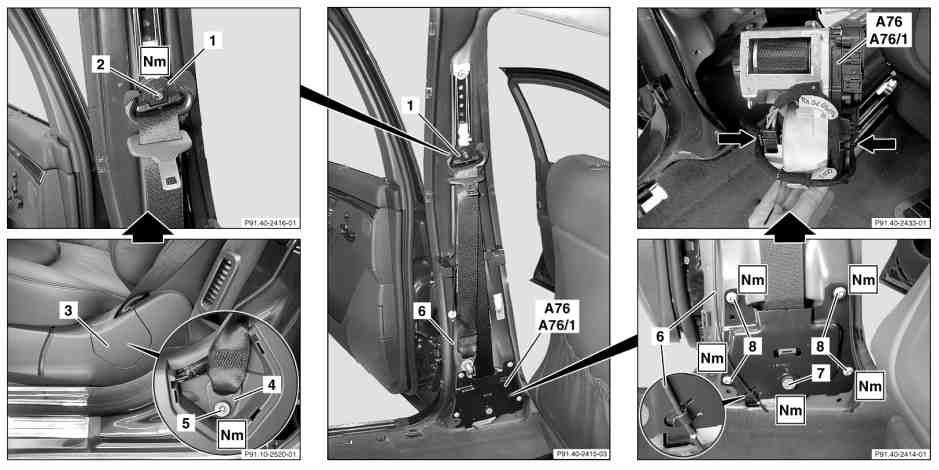
- Remove cover (3) of belt end fitting (4) and undo screw (5)
- Unscrew screw (2) from seat belt guide bracket (1)
- Unhook Bowden cable (6) on cover plate (see magnifying glass at bottom right)
- Undo TORX screw (8, 4 pieces) on cover plate. Installation: Tighten screw (7) to torque rating.
- Undo screw (7) from cover plate. Installation: Tighten screw (7) finger-tight only to cover plate.
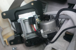
- Detach 6-pin coupling and 2-pin coupling (see arrows) of left front reversible emergency tensioning retractor (A76), and right front reversible emergency tensioning retractor
- (A76/1) Remove left front reversible emergency tensioning retractor (A76), and left front reversible emergency tensioning retractor (A76/1). Installation: Note different version (left/right) of seat belt emergency tensioning retractor and correct seating in cover plate. Noises from the automatic belt reel when rolling up belt are normal. The only available response to negative customer feedback regarding unacceptable noise levels is to replace the seat belt assembly with emergency tensioning retractor in its entirety. On no account should oil or grease be used to help eliminate noise. Automatic belt retractors that have been opened are no longer under warranty!
- Install in the reverse order
- Carry out diagnosis
Torque specification:
- Belt end fitting screw: 30 Nm
- Screw/nut on front seat belt guide bracket: 30 Nm
- Screw on front automatic belt reel: 30 Nm
- Bolt, emergency tensioning retractor cover plate to B-pillar: 10 Nm
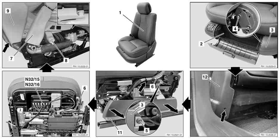
Remove/install front seat backrest (as of 01/09/2002)

|
|
- Remove front seat
- Open flap on stowage compartment (2)
- Unclip stowage compartment (2)
- Remove fire extinguisher (for fire extinguisher code 682)
- Remove bolts (4, 2 pieces) on the left side paneling (3)
- Unscrew and remove bolt (see arrow) on the belt end fitting cover (12)
- Unscrew bolt (5) on the left side paneling (3) (see enlarged detail)
- Detach left side paneling (3) in direction of travel
- Unclip lower side paneling (11) in the direction of the arrow (for the multicontour backrest for the driver seat code 404b and front passenger seat code 405b).
- Remove multicontour backrest control unit on front seat (for the multicontour backrest for the driver seat code 404b and front passenger seat code 405b).
- Remove bolt (see arrow) and bolt (8) on seat belt buckle (9) cover
- Unclip retaining lug (see enlarged detail) and remove seat belt buckle (9) cover
- Expose and detach electrical line (10) from the front seat backrest (1) to the front seat adjustment control unit with memory, on the left (N32/1), right (N32/2). Installation: Ensure that routing is chafing-free.
- Remove bolt (14, 2 pieces) on the right and left side from the backrest fitting (13)
- Remove front seat backrest (1) from seat adjustment mechanism
- Install in the reverse order
- Perform function test for the seatrest function
Torque specifications:
- Bolt on backrest fitting: 35 Nm
Remove/install front seat backrest (up to 31/08/2002)
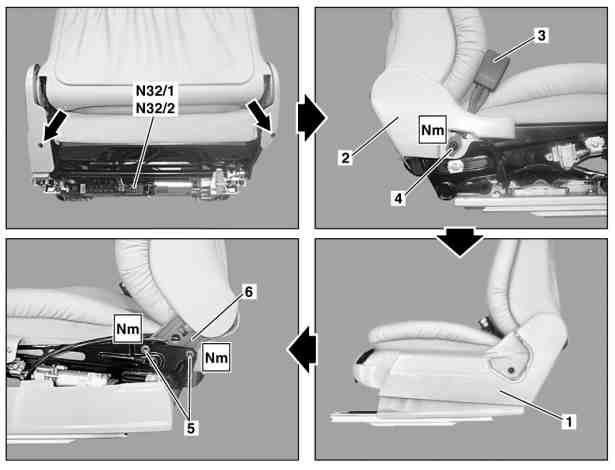
|
|
- Remove front seat
- Remove screw (arrow) on paneling (1)
- Remove trim panel (1)
- Remove bolt (4) and remove seat belt buckle (3)
- Remove screw (arrow) on paneling (2)
- Remove trim panel (2)
- Separate pneumatic line connector for lumbar support air cushion
- Remove multicontour backrest control unit from front seat (on vehicles with driver seat multicontour backrest, code 404b and passenger seat, code 405b).
- Disconnect backrest and head restraint adjustment connector from left front seat adjustment control unit with memory (N32/1) and right front seat adjustment control unit with memory (N32/2)
- Unscrew bolt (5, 2 each) from left and right backrest fitting (6)
- Remove front seat backrest from the seat adjustment mechanism
- Install in the reverse order
Torque specifications:
- Bolt at backrest fitting: 35 Nm (up to 30/11/2001 and as of 01/12/2001)
- Screw/nut on front seat belt buckle: 30 Nm
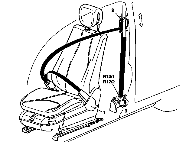
Remove/install seat belt (front seat) up to 31/08/2002
|
|
|
|
- Move front seat as far forward as possible with backrest upright
- Switch ignition off, withdraw ignition key
- Switch engine off, remove transmitter key from vehicle. With KEYLESS-GO code 889 keep transmitter key outside transmission range.
- Remove paneling on B-pillar
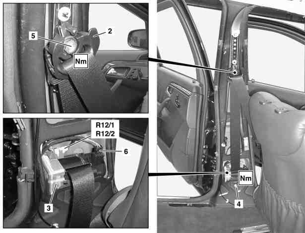
- Remove cover of belt end fitting (1) and undo screw
- Unscrew nut (5) from seat belt guide bracket (2)
- Release coupling on driver ETR [GUS] ignition squib (R12/1), passenger-side ETR [GUS] ignition squib (R12/2) and coupling (6)
- Remove screw (4) at automatic seat belt retractor (3)
- Remove automatic belt reel (3). Installation: Note different version (left/right) of seat belt emergency tensioning retractor and correct seating in catch. Noises from the automatic belt reel when rolling up belt are normal. The only available response to negative customer feedback regarding unacceptable noise levels is to replace the seat belt assembly with emergency tensioning retractor in its entirety. On no account should oil or grease be used to help eliminate noise. Automatic belt retractors that have been opened are no longer under warranty! If the seat belt with emergency tensioning retractor has been replaced, the defective unit must be disposed of properly.
- Install in the reverse order
- Carry out diagnosis
Torque specification:
- Belt end fitting screw: 30 Nm
- Screw/nut on front seat belt guide bracket: 30 Nm
- Screw on front automatic belt reel: 30 Nm
Seat belt height adjustment mechanism (front seat) removal and installation
|
|
- Remove front seat
- Remove paneling on B-pillar
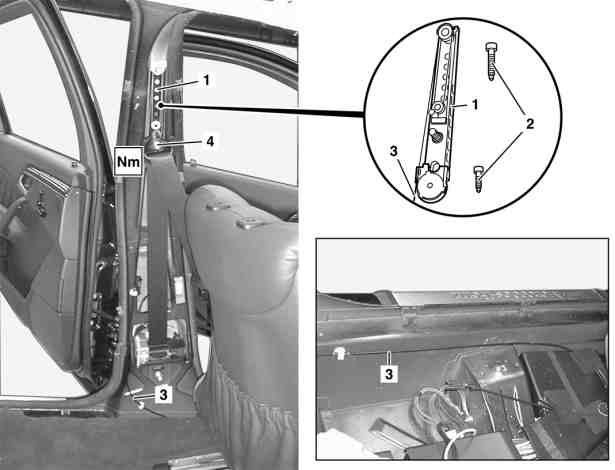
- Unclip Bowden cable (3) using Omega clip
- Unclip Bowden cable (3) from deflection in cable duct. Lift floor lining at left front until the deflection for the Bowden cable (3) in the cable duct can be easily accessed.
- Disassemble the Bowden cable (3) up to the belt height adjuster (1)
- Undo nut from seat belt guide bracket (4)
- Undo screw (2, 2 pieces) on belt height adjuster (1)
- Install in the reverse order
Torque specification:
- Screw/nut on front seat belt guide bracket: 30 Nm
- Screw on front automatic belt height adjuster: 25 Nm
