Front seats
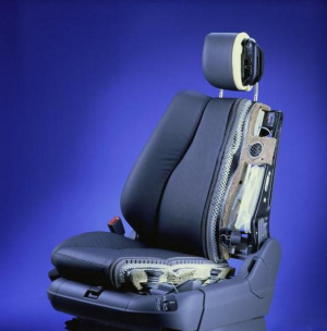
Front seat adjustment
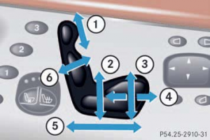
The seat adjustment switches are located on the front doors.
- (1) Head restraint height
- (2) Seat height
- (3) Seat cushion tilt
- (4) Seat cushion depth
- (5) Seat fore and aft adjustment
- (6) Seat backrest tilt
To adjust the seat switch on ignition or open the respective door.
Seat fore and aft adjustment: Press the switch forward or backward in the direction of arrow (5). Adjust seat to a comfortable seating position that still allows you to reach the accelerator/brake pedal safely. The position should be as far to the rear as possible, consistent with ability to properly operate controls.
Seat cushion tilt: Press the switch up or down in the direction of arrow (3) until your upper legs are lightly supported.
Seat cushion depth: Press the switch forward or backward in the direction of arrow (4) until your legs are supported comfortably.
Seat backrest tilt: Press the switch forward or backward in the direction of arrow (6) until your arms are slightly angled when holding the steering wheel.
Seat height: Press the switch up or down in the direction of arrow (2).
Head restraint height: Press the switch up or down in the direction of arrow (1).
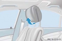
Head restraint tilt: Manually adjust the angle of the head restraint. Push or pull on the lower edge of the head restraint cushion.
Unoccupied front passenger seat automatic adjusting: The feature below is deactivated at the factory. If you wish to have it activated, use DAS. The front passenger seat head restraint automatically lowers after a few seconds when the front passenger seat is not occupied. This improves the driver's outward view as well as the forward view from the rear passenger compartment. When the front passenger seat is occupied again, the front passenger seat head restraint returns to the last set position within a few seconds. If the front passenger seat was moved fore or aft while not being occupied, the front passenger seat head restraint returns to a position that corresponds best with the seat’s axial position when the seat is occupied again.
Remove/install front seat backrest seat-back lining
|
|
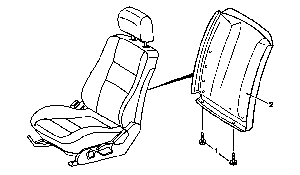
- Slide the front seat forwards with the longitudinal adjustment mechanism
- Slide backrest forwards with the inclination adjustment mechanism
- Unscrew screws (1)
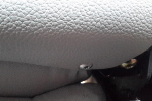
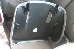
- Pull seat-back lining (2) down and take off. Installation: slide seat-back lining into top of backrest.
- Install in the reverse order
 |
 |
 |
Remove and install headrest guide on front seat
|
|
Remove:
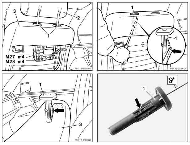
- Remove head restraint (2)
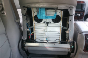
- Remove tensioning element (seat-back lining) from front seat backrest
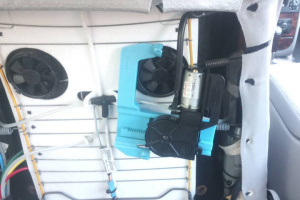
- Remove head restraint raise/lower motor (M27m4/M28m4). Push motor to right first and then remove downwards.
- Release catch at head restraint guide (1) using screwdriver. Push back catch (arrow) at head restraint guide (1) using screwdriver and pull head restraint (1) out upwards.
- Release catch at head restraint guide (1) using pulling hook. Insert pulling hook into top of head restraint guide (1), push back catch and pull out head restraint upwards.
Install:
- Insert head restraint guide (1) into backrest frame of front seat backrest (3). Do not damage backrest upholstery. Catch (arrow) must point towards rear.
- Engage head restraint guide (1) in backrest frame of front seat backrest (3)
- Install head restraint raise/lower motor (M27m4/M28m4). Insert motor facing upwards and then push to left until it engages in backrest frame.
- Fit seat-back lining to front seat backrest (3)
- Install head restraint (2)
| Error Code | Generated By | Description |
|---|---|---|
| B1203 | ESA-FL - Electronic seat adjustment front left | Hall sensor of component M27m4 (Head restraint raise/lower motor) is faulty |
Facelift head restraint motor A2209700026 fits both sides.
Note: when installing new motor the new motor may be need to be moved manually to the position of the old motor, otherwise it may be encountered that motor is not able to move the full distance.
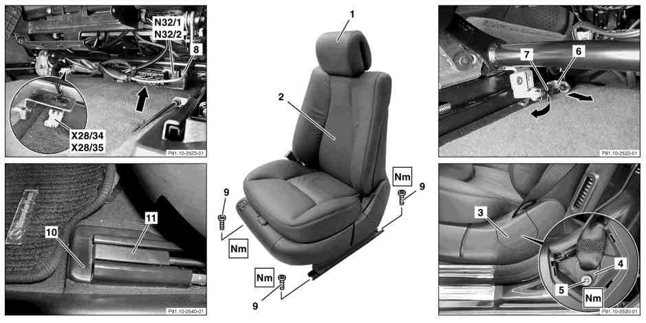
Remove/install front seat (as of 01/09/2002)
- Switch off ignition, remove ignition key (vehicles without KEYLESS-GO, code 889).
- Switch off engine, remove transmitter key from vehicle (with KEYLESS-GO, code 889). Keep transmitter key out of transmitter range.
- Remove head restraint (1)
- Adjust front seat (2) to front. Move front and rear seat cushions all the way up. Move backrest into upright position.
- Remove cover (3) at rear side paneling
- Remove screw/bolt (5) at belt end fitting (4). Installation: When screwing on, ensure that belt end fitting (4) remains mobile.
- Remove rear screws/bolts (9) from seat rails. Remove cover (11) from seat rail.
- Turn retaining clamp (7) at Bowden cable in direction of transmission tunnel and remove
- Unhook grommet (6) with Bowden cable from bracket
- Position front seat (2) to rear
- Remove front screw/bolt (9) from seat rails. Remove cover (11) from seat rail.
- Pry off pneumatic line plug coupling (8) with open end wrench, size 7. Slightly incline seat toward rear in vehicle.
- Detach connecting coupling (see arrow) from front seat adjustment control unit with memory, left (N32/1), right (N32/2). Slightly incline seat toward rear in vehicle.
- Disconnect 2-pin driver seat connecting point buckle emergency tensioning retractor connector (X28/34), 2-pin front passenger seat connecting point buckle emergency tensioning retractor connector (X28/35). Slightly incline seat toward rear in vehicle.
- Remove seat rail final cover (10) from seat rails
- Lift front seat (2) and remove
- Install in the reverse order
- Check function of seat adjustment mechanism
Torque specifications:
- Bolt to seat runner: 45 Nm
- Screw on belt end fitting: 30 Nm
Remove/install front seat (up to 31/08/2002)
|
|
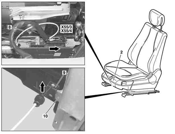
|
|
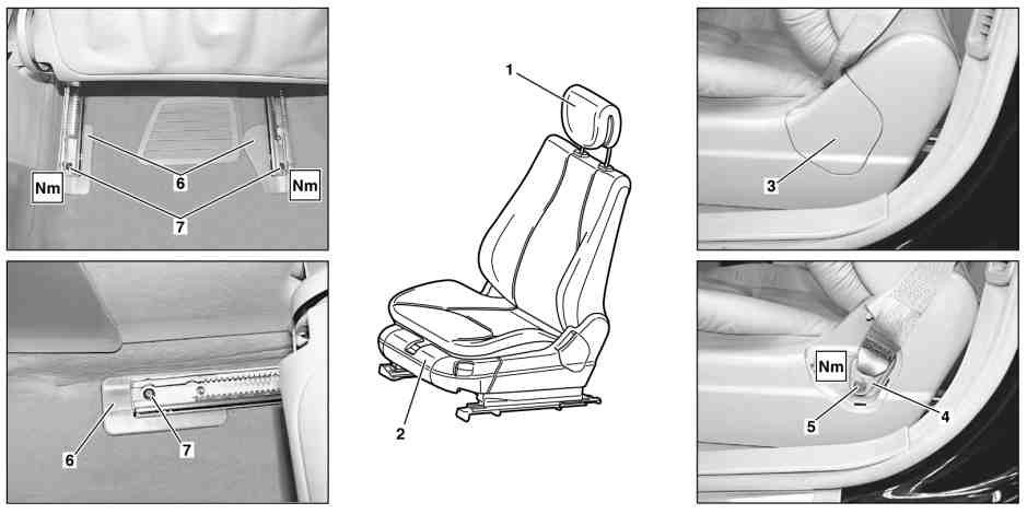
- Remove head restraint (1)
- Adjust front seat (2) to front
- Remove cover (3) above belt end fitting (4)
- Remove bolt (5) from seat belt end fitting (4)
- Remove screws (7) at the back of the seat rails
- Remove covers (6) at rear of seat rails
- Position front seat (2) to rear
- Remove screws (7) at the front of the seat rails
- Remove covers (6) at front of seat rails
- Detach plug connection from pneumatic line (8) and left front seat connector block (X55/3) and right front seat connector block (X55/4) from front seat cushion. Disconnect plug connection on pneumatic line (8) with 7 mm open end wrench.
- Detach retaining clamp (9) for Bowden cable seat belt height adjustment at seat adjustment mechanism (10) in direction of arrow
- Lift front seat (2) and remove
- Install in the reverse order
Torque specification:
- Bolt to seat runner: 50 Nm (up to 30/11/2001), 45 Nm (as of 01/12/2001)
- Screw on belt end fitting: 30 Nm
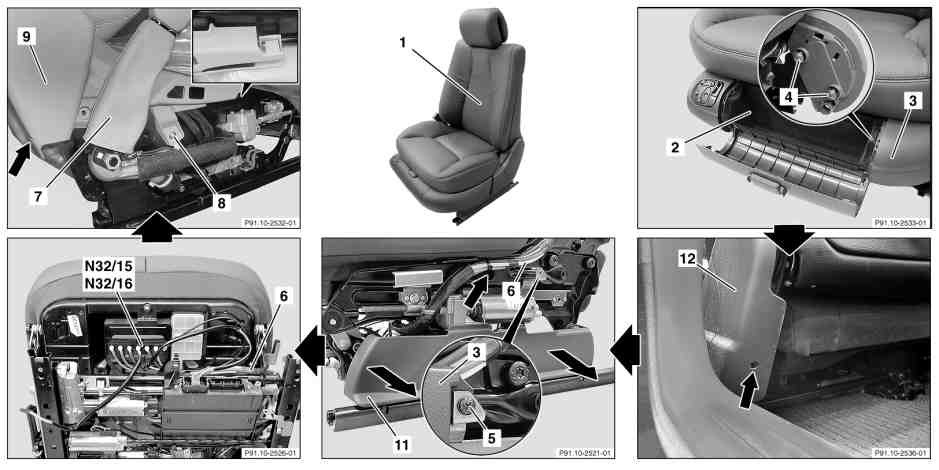
Remove/install front seat backrest (as of 01/09/2002)

|
|
- Remove front seat
- Open flap on stowage compartment (2)
- Unclip stowage compartment (2)
- Remove fire extinguisher (for fire extinguisher code 682)
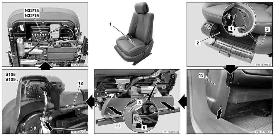
- Remove bolts (4, 2 pieces) on the left side paneling (3)
- Unscrew and remove bolt (see arrow) on the belt end fitting cover (12)
- Unscrew bolt (5) on the left side paneling (3) (see enlarged detail)
- Detach left side paneling (3) in direction of travel
- Unclip lower side paneling (11) in the direction of the arrow (for the multicontour backrest for the driver seat code 404b and front passenger seat code 405b).
- Remove multicontour backrest control unit on front seat (for the multicontour backrest for the driver seat code 404b and front passenger seat code 405b).
- Remove bolt (see arrow) and bolt (8) on seat belt buckle (9) cover
- Unclip retaining lug (see enlarged detail) and remove seat belt buckle (9) cover
- Expose and detach electrical line (10) from the front seat backrest (1) to the front seat adjustment control unit with memory, on the left (N32/1), right (N32/2). Installation: Ensure that routing is chafing-free.
- Remove bolt (14, 2 pieces) on the right and left side from the backrest fitting (13)
- Remove front seat backrest (1) from seat adjustment mechanism
- Install in the reverse order
- Perform function test for the seatrest function
Torque specifications:
- Bolt on backrest fitting: 35 Nm
Remove/install front seat backrest (up to 31/08/2002)
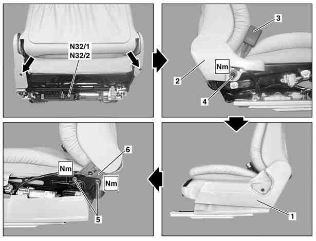
|
|
- Remove front seat
- Remove screw (arrow) on paneling (1)
- Remove trim panel (1)
- Remove bolt (4) and remove seat belt buckle (3)
- Remove screw (arrow) on paneling (2)
- Remove trim panel (2)
- Separate pneumatic line connector for lumbar support air cushion
- Remove multicontour backrest control unit from front seat (on vehicles with driver seat multicontour backrest, code 404b and passenger seat, code 405b).
- Disconnect backrest and head restraint adjustment connector from left front seat adjustment control unit with memory (N32/1) and right front seat adjustment control unit with memory (N32/2)
- Unscrew bolt (5, 2 each) from left and right backrest fitting (6)
- Remove front seat backrest from the seat adjustment mechanism
- Install in the reverse order
Torque specifications:
- Bolt at backrest fitting: 35 Nm (up to 30/11/2001 and as of 01/12/2001)
- Screw/nut on front seat belt buckle: 30 Nm
Remove/install driver seat cushion (as of 01/09/2002)
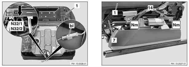
- Remove front seat. Move seat cushion all the way up and to center position so that rear bolt (14) on belt buckle is accessible.
- Open flap in stowage compartment (2)
- Unclip stowage compartment (2)
- Remove fire extinguisher (with fire extinguisher, code 682).
- Unscrew bolts (4, 2 each) from left side paneling (3)
- Unscrew bolt (see arrow) at rear of paneling (13) on belt end fitting and remove
- Unscrew bolt (5) from left side paneling (3)
- Remove left side paneling (3) in direction of travel
- Unclip bottom side paneling (11) in direction of arrow (with driver seat multicontour backrest, code 404b, passenger seat, code 405b).
- Remove pneumatic lines from lumbar support control valve
- Remove connector coupling from left front multicontour backrest switch group (S109), right front multicontour backrest switch group (S108) (on driver seat multicontour backrest code 404b, passenger seat code 405b or left dynamic seat including multicontour seat code 433, right code 434).
- Remove omega clip (see arrow) from seat cushion frame
- Remove connector coupling from dynamic seat switch (on left dynamic seat incl. multicontour seat code 433, right code 434).
- Remove multicontour backrest control unit from front seat (with driver seat multicontour backrest, code 404b, passenger seat, code 405b).
- Unscrew stowage compartment retaining frame (12) from cushion frame
- Unscrew bolt (14, 2 each) and slide seat cushion (1) on seat adjustment mechanism (7) toward front. Do not yet remove seat cushion (1) from seat adjustment mechanism.
- Disconnect blue connector on fan motor (bl) (for code (401a) front comfort seat, incl. seat heating and seat ventilation).
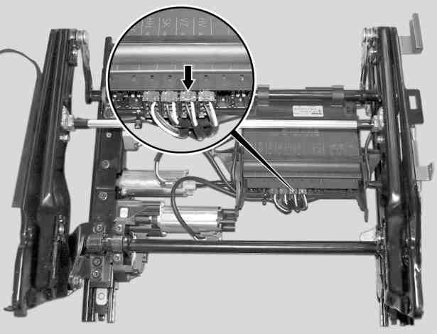
- Remove coupling for seat cushion heater (see arrow in magnifying glass) from left front seat adjustment control unit with memory (N32/1), right front seat adjustment control unit with memory (N32/2) (for front comfort seats, incl. seat heating and seat ventilation vehicles, code 401a or right and left front seat heaters or code 873).
- Remove seat cushion (1) from seat adjustment mechanism (7)
- Install in the reverse order
- Check seat adjustment for proper function
Torque specifications:
- Bolt, seat cushion to seat adjustment mechanism: 15 Nm
Remove/install driver seat cushion (up to 31/08/2002)
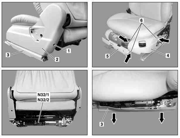
|
|
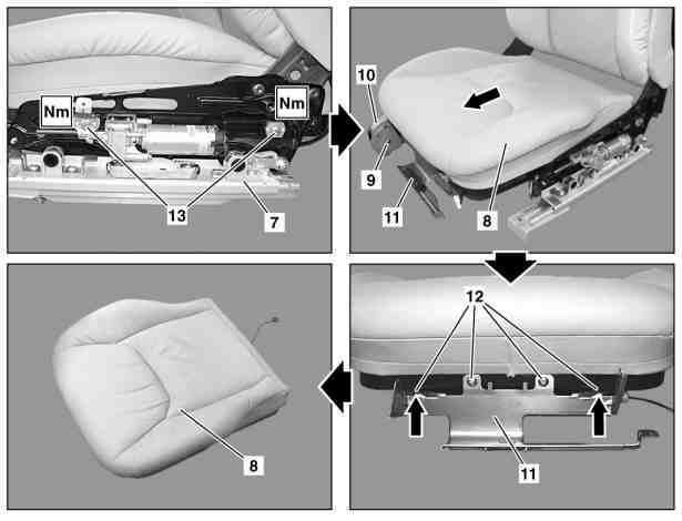
|
|
- Remove front seat
- Remove screw (1) and remove paneling (2)
- Open cap (5) and remove fire extinguisher (with fire extinguisher, code 682).
- Remove screws (6, arrows) and remove paneling (4) and cap (5)
- Pull off paneling (3) in direction of arrow. Ensure that retaining lugs are not damaged.
- Disconnect connector from seat cushion heater on left front seat adjustment control unit with memory (N32/1) and right front seat adjustment control unit with memory (N32/2).
- Remove multicontour backrest control unit from front seat (with driver seat multicontour backrest, code 404b, passenger seat, code 405b).
- Remove screw (9) and remove paneling (10)
- Remove screws (13) and remove seat cushion (8) forwards from the seat adjustment mechanism
- Remove screws (12, arrows) from the seat cushion (8) and remove bracket (11) from the seat cushion (8)
- Install in the reverse order
Torque specifications:
- Bolt, seat cushion to seat adjustment mechanism: 15 Nm (up to 30/11/2001 and as of 01/12/2001)
Remove/install seat belt (front seat) as of 01/09/2002
- Move front seat as far forward as possible with backrest upright
- Switch ignition off, withdraw ignition key
- Switch engine off, remove transmitter key from vehicle. With KEYLESS-GO code 889 keep transmitter key outside transmission range.
- Remove paneling on B-pillar
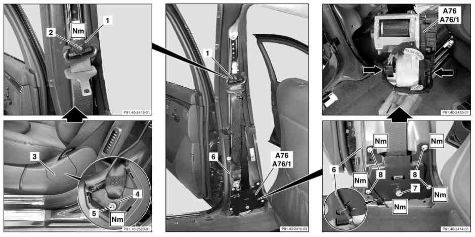
- Remove cover (3) of belt end fitting (4) and undo screw (5)
- Unscrew screw (2) from seat belt guide bracket (1)
- Unhook Bowden cable (6) on cover plate (see magnifying glass at bottom right)
- Undo TORX screw (8, 4 pieces) on cover plate. Installation: Tighten screw (7) to torque rating.
- Undo screw (7) from cover plate. Installation: Tighten screw (7) finger-tight only to cover plate.
- Detach 6-pin coupling and 2-pin coupling (see arrows) of left front reversible emergency tensioning retractor (A76), and right front reversible emergency tensioning retractor
- (A76/1) Remove left front reversible emergency tensioning retractor (A76), and left front reversible emergency tensioning retractor (A76/1). Installation: Note different version (left/right) of seat belt emergency tensioning retractor and correct seating in cover plate. Noises from the automatic belt reel when rolling up belt are normal. The only available response to negative customer feedback regarding unacceptable noise levels is to replace the seat belt assembly with emergency tensioning retractor in its entirety. On no account should oil or grease be used to help eliminate noise. Automatic belt retractors that have been opened are no longer under warranty!
- Install in the reverse order
- Carry out diagnosis
Torque specification:
- Belt end fitting screw: 30 Nm
- Screw/nut on front seat belt guide bracket: 30 Nm
- Screw on front automatic belt reel: 30 Nm
- Bolt, emergency tensioning retractor cover plate to B-pillar: 10 Nm
Remove/install seat belt (front seat) up to 31/08/2002
|
|
|
|
- Move front seat as far forward as possible with backrest upright
- Switch ignition off, withdraw ignition key
- Switch engine off, remove transmitter key from vehicle. With KEYLESS-GO code 889 keep transmitter key outside transmission range.
- Remove paneling on B-pillar
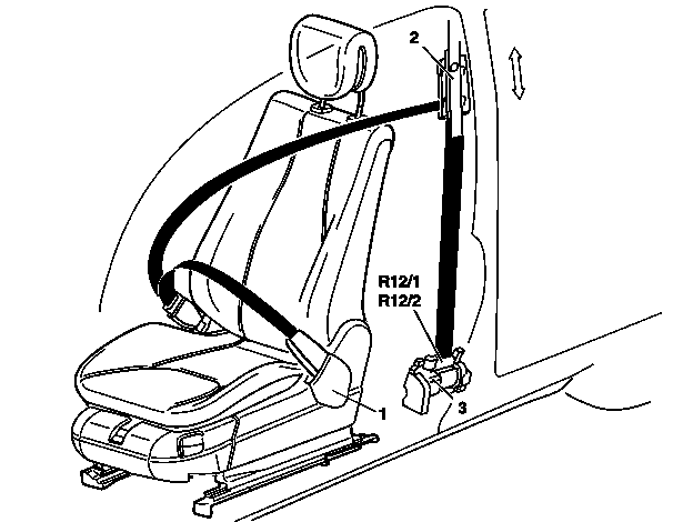
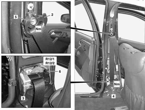
- Remove cover of belt end fitting (1) and undo screw
- Unscrew nut (5) from seat belt guide bracket (2)
- Release coupling on driver ETR [GUS] ignition squib (R12/1), passenger-side ETR [GUS] ignition squib (R12/2) and coupling (6)
- Remove screw (4) at automatic seat belt retractor (3)
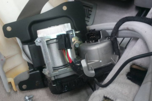
- Remove automatic belt reel (3). Installation: Note different version (left/right) of seat belt emergency tensioning retractor and correct seating in catch. Noises from the automatic belt reel when rolling up belt are normal. The only available response to negative customer feedback regarding unacceptable noise levels is to replace the seat belt assembly with emergency tensioning retractor in its entirety. On no account should oil or grease be used to help eliminate noise. Automatic belt retractors that have been opened are no longer under warranty! If the seat belt with emergency tensioning retractor has been replaced, the defective unit must be disposed of properly.
- Install in the reverse order
- Carry out diagnosis
Torque specification:
- Belt end fitting screw: 30 Nm
- Screw/nut on front seat belt guide bracket: 30 Nm
- Screw on front automatic belt reel: 30 Nm
Seat belt height adjustment mechanism (front seat) removal and installation
|
|
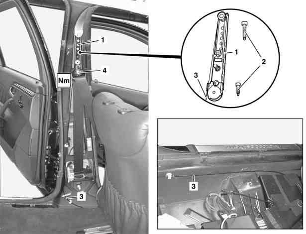
- Remove front seat
- Remove paneling on B-pillar
- Unclip Bowden cable (3) using Omega clip
- Unclip Bowden cable (3) from deflection in cable duct. Lift floor lining at left front until the deflection for the Bowden cable (3) in the cable duct can be easily accessed.
- Disassemble the Bowden cable (3) up to the belt height adjuster (1)
- Undo nut from seat belt guide bracket (4)
- Undo screw (2, 2 pieces) on belt height adjuster (1)
- Install in the reverse order
Torque specification:
- Screw/nut on front seat belt guide bracket: 30 Nm
- Screw on front automatic belt height adjuster: 25 Nm
Remove/install front seat multicontour backrest control module (code 404b/405b)
- Remove front seat
- Unscrew screw (2) and remove frame (3)
- Remove multicontour backrest, front left (N32/15) or right (N32/16)
- Expose control module connecting cable (6) and disconnect from front seat adjustment control module (see arrow)
- Expose switch group connecting cable (7) and disconnect from multicontour backrest switch group
- Open catch (5) and remove pneumatic line connecting rail (1). Open catch (5) using small screwdriver (see arrow).
- Unclip black pneumatic line with diam. of 4 mm (sw) to overpressure reservoir (4) (only if seat cushion or backrest has to be removed).
- Install in the reverse order
- Check multicontour seat backrest for proper function
Remove/install front seat adjustment mechanism
|
|
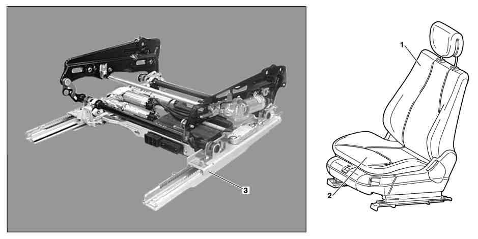
- Remove front seat backrest (1)
- Remove driver's seat cushion (2)
- Remove front seat control module
- Remove front seat adjustment motor group (seat cushion) - up to 30/06/2001.
- Remove front seat adjustment motor group (seat cushion) (only for front and rear seat cushion and front seat forward and backward) - as of 01.07.2001.
- Remove front seat adjustment motor group (seat cushion) (only for seat cushion forward and backward) - as of 01/07/2001 and up to 31/08/2002, as of 01/09/2002.
- Install in the reverse order
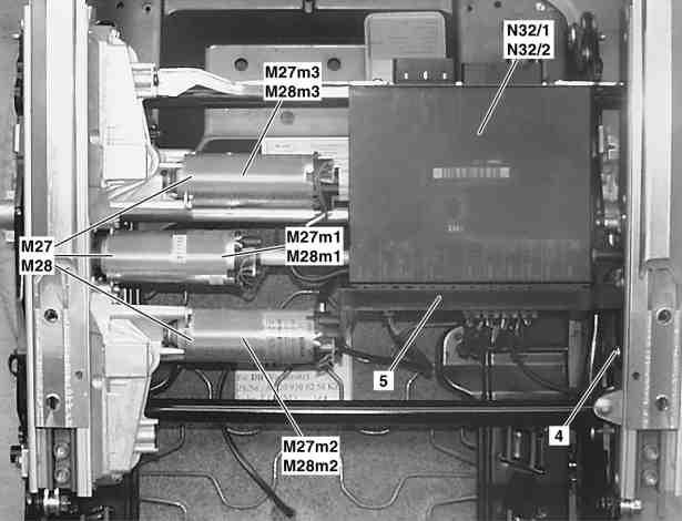
Remove/install front seat control module (as of 01/07/2001)
- Remove front seat
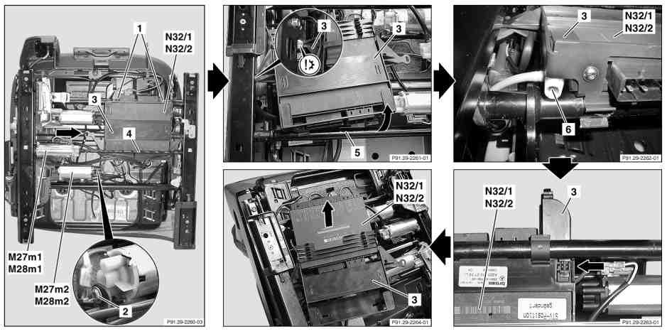
- Remove all connectors to front and rear side of left (N32/1) and right (N32/2) front seat adjustment control module with memory
- Slacken tie straps (see arrow) at control module bracket lug (3). Installation: Use new tie straps.
- Unscrew bolt (1, 2 pcs.) at front of left (N32/1) and right (N32/2) front seat adjustment control module with memory
- Unscrew bolt (2, see magnification) from rear up/down motor (M27m2, M28m2)
- Detach flexible shaft (4) from forward/back motor (M27m1, M28m1)
- Carefully release front control module bracket (3) from transverse rod (5), (see arrow) until both plastic retaining clamps on underside of control module bracket (3) have been unclipped. Control module bracket (3) is fixed to the seat frame with a rivet (see magnification).
- Unclip pneumatic line (6) at front left (N32/1) and right (N32/2) side of left front seat adjustment control module with memory
- Unclip left (N32/1) and right (N32/2) front seat adjustment control module with memory from control module bracket (3) latching lug (see arrow) at front right side
- Push left (N32/1) and right (N32/2) front seat adjustment control module with memory from control module bracket (3)
- Install in the reverse order
- Perform front seat adjustment function test
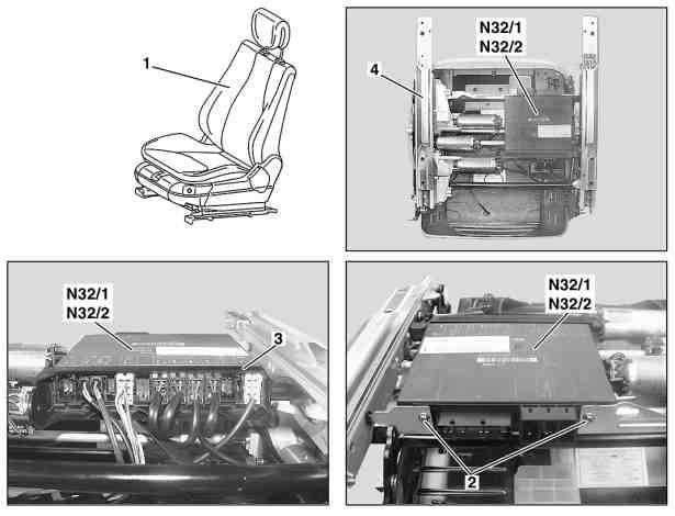
Remove/install front seat control module (up to 30/06/2001)
- Remove front seat (1)
- Disconnect all electrical connectors (3)
- Unscrew internal Torx bolts (2)
- Remove left front seat adjustment control module with memory (N32/1), right (N32/2) from bracket in seat adjuster (4)
- Install in the reverse order
- Perform function check on electric seat adjustment
Retrofit front seat height adapter
|
|
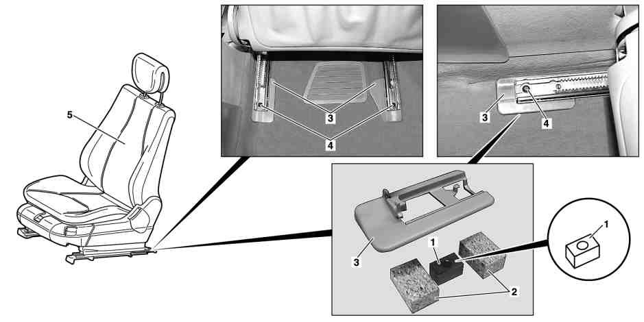
- Remove bolts (4, 4 pieces) on the front and rear seat rail
- Raise front seat frame, place spacers (1) (part number A2209101736) on the right and left as well as at the front and rear under the under the seat rails and fasten with the bolts contained in the accessories. Do not damage covers (3).
- Clamp foamed material (2) in each case in front of and behind the spacer (1) under the covers (3) of the seat rails
- Check seat adjustment for proper function
- If the package changes, supplement the code or designation of the relevant special equipment on the vehicle data card
Torque specifications:
- Bolt to seat runner: 50 Nm (up to 30/11/2001)
Front seat adjustment control module with memory
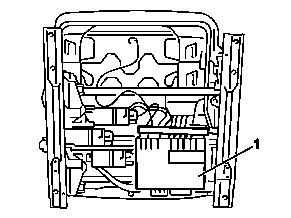
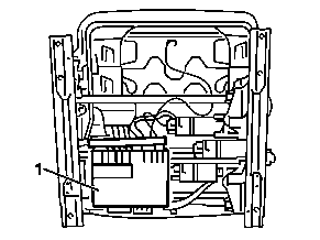
The left/right front seat adjustment control module with memory (N32/1,N32/2) is located under the seat cushion of the left/right front seat.
|
The left/right front seat adjustment control module with memory (N32/1,N32/2) connected to the CAN bus has the following tasks :
- Control of the six servo DC motors for the front seat adjustment motor group with memory (M27,M28)
- Position recognition of these motors
- Storage of the seat position by the memory feature as of 1.6.01 expanded by one memory location
- Calling up and approaching seat positions stored previously within the framework of the memory feature
- Approaching the permanently stored seat default settings depending on the longitudinal position of the seat within the framework of the Ergo function up to 31.5.01
- Control of heated seats/seat ventilation (special equipment)
- Control of the seat belt wearing comfort function
- Monitoring of backrest locking by the left/right front seat backrest release microswitch (S91/3,S92/3), (model 215 only)
In addition the control module is used for contacting of:
- Left/right front seat belt buckle restraint systems switch (S68/3,S68/4) with AB and GUS (only USA)
- Left/right front buckle microswitch (S68/9,S68/10)
- Left side control module - passenger seat occupied and child seat recognition sensor (B48) (right hand steering only)
- Right side control module - occupation recognition and automatic child seat recognition in front passenger's seat (B48) (left hand steering vehicle only)
- Left/right front multicontour backrest control module (N32/15,N32/16) (special equipment)
- Vehicle-sensitive seat belt lock sensor (A60), (model 215 only)
- Left /levtfront seat backrest angle microswitch group (S91/1,S92/1), (model 215 only)
The signal for the left/right front seat seat occupation is acquired by the left/right front seat adjustment control module with memory and is transmitted to the automatic air conditioning control and operating module via the interior bus (CAN B).
From this information the automatic air conditioning control and operating module increases, for example, the automatic blower level of the ventilation depending on the number of people in the vehicle.
Furthermore, the blower capacity adjusted in the automatic air conditioning control and operating module is read in by the left/right front seat adjustment control module with memory in order to adapt the seat ventilation by actuating the fans built into the seat
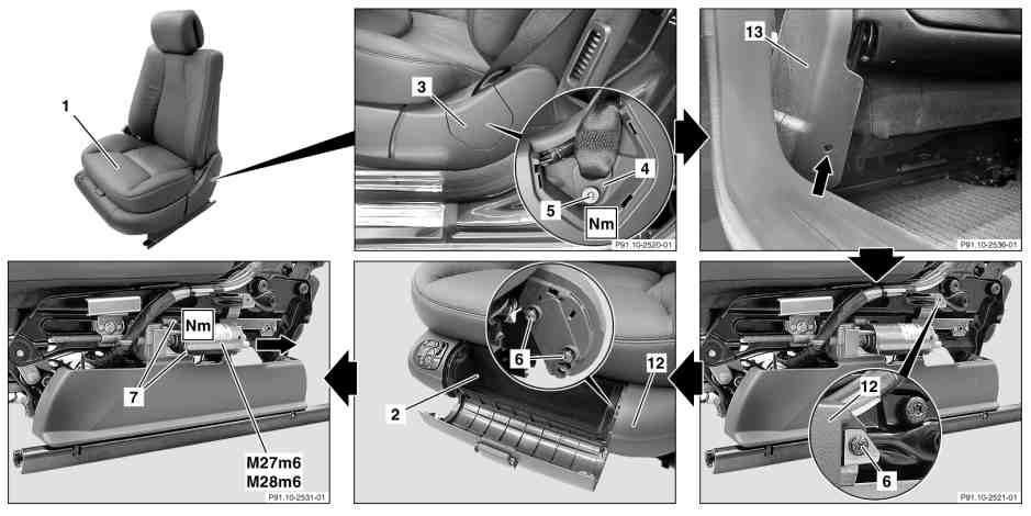
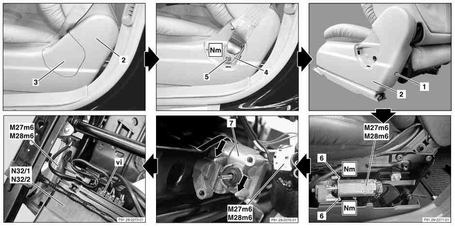
Remove/install front seat (seat cushion forward/back) adjusting motors (as of 01/09/2002)
- Adjust front seat (1) to front. Move front and back seat cushions up as far as possible.
- Remove cover (3) from rear side trim (13)
- Unscrew screw (5) from belt end fitting (4). Installation: When screwing on, please ensure that the belt end fitting (4) remains mobile.
- Remove screw (see arrow) from rear side trim (13)
- Unscrew screw (6, see magnification) from left side trim (12)
- Open stowage compartment flap (2)
- Unclip and remove stowage compartment (2)
- Remove fire extinguisher (for vehicles with fire extinguisher code 682)
- Unscrew screws (6, 2 screws) from left side trim (12)
- Pull off left side trim (12) in direction of travel
- Unscrew screw (7, 2 screws) from seat cushion forward/back motor (M27m6, M28m6)
- Remove seat cushion forward/back motor (M27m6, M28m6) from transmission. Shaft remains in transmission.
- Unplug connector from seat cushion forward/back motor (M27m6, M28m6)
- Install in the reverse order
- Perform function check of seat cushion forward/back facility
Torque specification:
- Bolt of seat adjustment motor: 4 Nm
- Screw/nut on front seat belt buckle: 30 Nm
Remove/install front seat (seat cushion forward/back) adjusting motors (as of 01/07/2001 up to 31/08/2002)
- Move front seats toward front. Move front and back seat cushions up as far as possible.
- Remove cover (3) from side trim (2)
- Unscrew screw (5) from belt end fitting (4). Installation: When screwing on, please ensure that the belt end fitting (4) remains mobile.
- Unscrew bolt (1) and unclip and remove upper trim (2)
- Unscrew screws (6, 2 screws) from seat cushion forward/back motor (M27m6, M28m6)
- Remove seat cushion forward/back motor (M27m6, M28m6) from transmission (7). Shaft remains in transmission (7). Installation: Motor must be inserted into pilot stud (arrows).
- Unclip connecting cable to underside of left (N32/1) and right (N32/2) front seat adjustment control unit with memory. Installation: Carefully clip connecting cable into retaining clamps on underside of control unit.
- Unplug violet coupling (vi) from left (N32/1) and right (N32/2) front seat adjustment control unit with memory
- Remove seat cushion forward/back motor (M27m6, M28m6) with connecting cable
- Install in the reverse order
- Check seat adjustment for proper function
Torque specification:
- Bolt of seat adjustment motor: 4 Nm
- Screw/nut on front seat belt buckle: 30 Nm
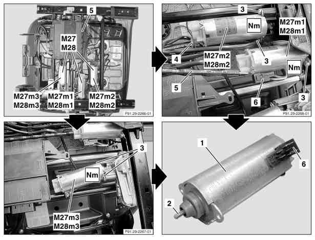
Remove/install front seat (seat frame forward/back, seat cushion forward/back, up/down) adjusting motors (as of 01/07/2001)
- Remove front seat (1)
- Unscrew screw (3, 2 pcs.) from front up/down motor (M27m3, M28m3). Only when replacing front up/down motor (M27m3, M28m3).
- Lift front up/down motor (M27m3, M28m3) slightly from transmission, kink over flexible shaft (2) and remove. Only when replacing front up/down motor (M27m3, M28m3).
- Detach seat adjustment shaft (5) from forward/back motor (M27m1, M28m1). Only when replacing forward/back motor (M27m1/M28m1).
- Unscrew screws (3, 2 pcs.) from forward/back motor (M27m1, M28m1). Only when replacing forward/back motor (M27m1/M28m1).
- Detach forward/back motor (M27m1, M28m1) from transmission. Only when replacing forward/back motor (M27m1/M28m1). Flexible shaft (2) remains in transmission.
- Unscrew screw (4) from control module bracket. Only when replacing rear up/down motor (M27m3, M28m3).
- Unscrew screw (3, 2 pcs.) from rear up/down motor (M27m2, M28m2). Only when replacing rear up/down motor (M27m3, M28m3).
- Remove rear raise/lower motor (M27m2/M28m2) from transmission. Only when replacing rear up/down motor (M27m3, M28m3).
- Detach electrical plug (6) from motor (1). Installation: Slide flexible shaft (2) into motor (1) as far as it will go.
- Install in the reverse order
- Perform function check of respective electric seat adjuster
Torque specification:
- Bolt of seat adjustment motor: 4 Nm
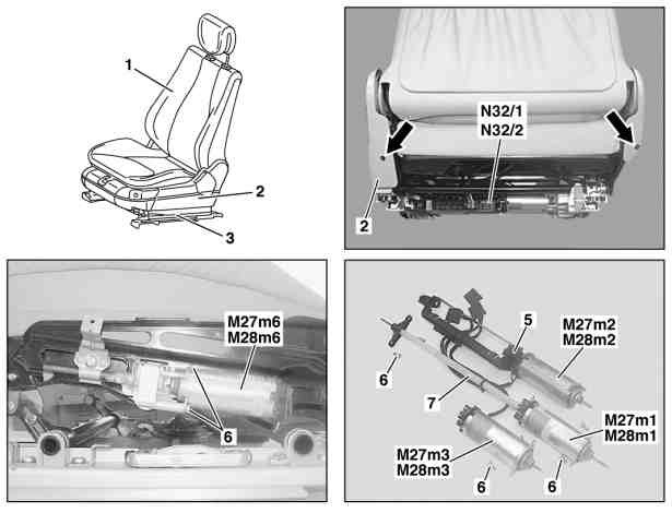
Remove/install front seat adjusting motors (up to 30/06/2001)
- Remove front seat (1)
- Undo screws (arrows) on side paneling (2)
- Remove side paneling (2) and (3) from front seat (1)
- Undo bolts (6) on seat cushion fore/aft motor (M27m6) and (M28m6) and remove motor
- Remove left front seat adjustment control unit with memory (N32/1), right front seat adjustment control unit with memory (N32/2)
- Undo bolt (4) from the bracket (5) for the left front seat adjustment control unit with memory (N32/1), right front seat adjustment control unit with memory (N32/2)
- Remove fore/aft motor (M27m1) and (M28m1). Remove screws (6).
- Remove rear up/down motor (M27m2) and (M28m2). Remove screws (6).
- Remove front up/down motor (M27m3) and (M28m3). Remove screws (6).
- Exchange coupling assignment on seat adjustment of fore/aft motors (M27m1) and (M28m1) (only for models 220.0/1 up to chassis end number 189590, when installing new fore/aft motors (M27m1) and (M28m1)).
- Undo bracket (5) for left front seat adjustment control unit with memory (N32/1), right front seat adjustment control unit with memory (N32/2) and the strut (7) of the motor group
- Install in the reverse order
- Check seat adjustment for proper function
Torque specifications:
- Bolt of seat adjustment motor: 4 Nm
Exchange coupling assignment on seat adjustment
- Detach coupling (arrow) on connector assignment.
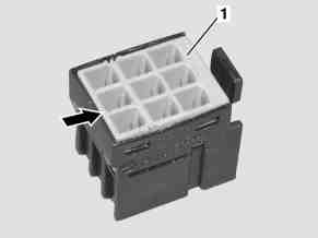
- Using a suitable tool, slide contact retainer (1) in direction of arrow out of locked position.
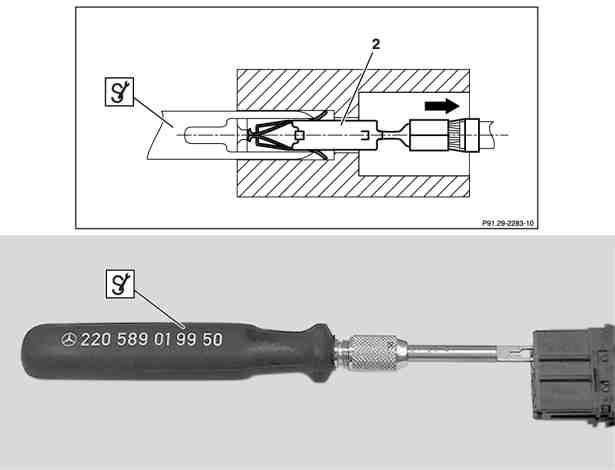
- Insert unlocking tool into coupling of contact cavity 5 and remove female contact from coupling by pulling lightly on cable.
- Insert unlocking tool into coupling of contact cavity 6 and remove female contact from coupling by pulling lightly on cable.
- Exchange the female contact from contact cavity 6 with the female contact from contact cavity 5.
- During installation pull lightly on the cables in contact cavities 5 and 6 to check that the female contacts have engaged properly into the housing.
Remove/install front seat cushion covering (as of 01/09/2002)
|
|
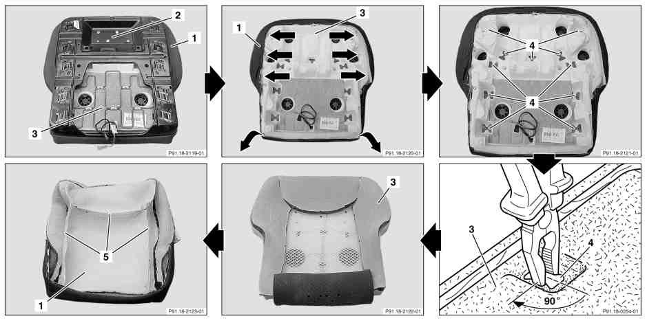
- Remove driver's seat cushion. Place driver's seat cushion on suitable surface with upholstery (1) facing downwards.
- Unhook covering (1) from clip groove around cushion frame (2). Relieve seat cushion cover (1) tension by pressing cushion frame (2) down.
- Remove cushion frame (2) from foam rubber padding (3)
- Unhook three stapling clips (see arrows) from foam rubber padding (3) at each side. Pull upholstery (1) over outer edge of foam rubber padding (3).
- Remove stapling clips (4, 11 pcs.) from stitching wires (5). Do this by rotating stapling clips (4) 90° using flat nose pliers. Installation: Use push-in tool.
- Remove upholstery (1) from foam rubber padding (3). Installation: Align upholstery (1) on foam rubber padding (3).
- Pull stitching wire (5) out of material sleeves on upholstery (1). Only when replacing upholstery (1).
- Install in the reverse order
Remove/install front seat cushion covering (up to 31/08/2002)
|
|
|
|
Remove:
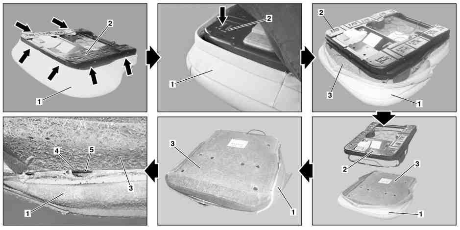
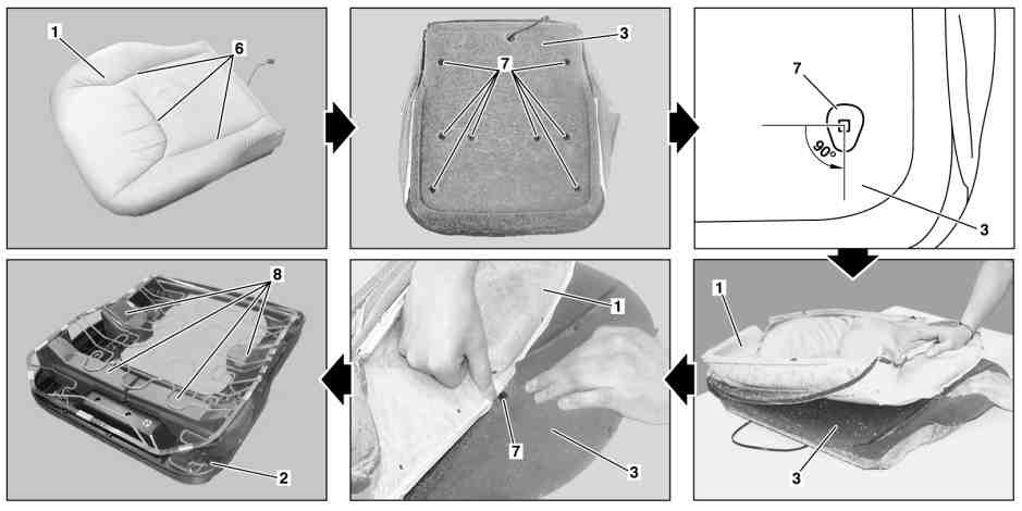
- Remove driver's seat cushion. Place driver's seat cushion on suitable surface with upholstery (1) facing downwards.
- Unclip upholstery all way round (1) from clip groove (arrows) in cushion frame (2). Relieve strain on upholstery (1) by pushing down the cushion frame.
- Remove cushion frame (2) from the rubberized fiber matting (3)
- Remove side upholstery clips (4) from stitching wires (5). Pull upholstery (1) over outer edge of rubberized fiber matting (3).
- Remove upholstery clips (7, 8 pcs.) from stitching wires (6). Do this by rotating upholstery clips (7) 90° using flat nose pliers.
- Remove upholstery (1) from rubberized fiber matting (3).
- Pull stitching wires (5, 6) from upholstery (1). Only when replacing upholstery (1).
Intall:
- Slide stitching wires (5) and (6) into material sleeves on upholstery (1) and straighten out. Only when fitting new upholstery (1).
- Press in upholstery clips (7, 8 pcs.) into rear of rubberized fiber matting (3) and straighten out
- Fold upholstery (1) to side, place on rubberized fiber matting (3) and straighten out
- Use press-in tool to insert stitching wires (6) into upholstery clips (7) Installation tool for stitching wire
- Insert lateral stapling clips (4) into stitching wires (5). Pull upholstery (1) over outer edge of rubberized fiber matting (3) at side and front.
- Insert cushion frame (2) into rubberized fiber matting (3). With foam rubber wedges (8, 4 pcs.) inserted into cushion frame (2).
- Insert upholstery (1) all way round into clip groove. Relieve strain on upholstery (1) by pushing down the cushion frame. Note retaining clamps.
- Install driver's seat cushion
Remove front seat backrest cover
|
|
|
|
|
|
Remove:
- Remove head restraint guide on front seat
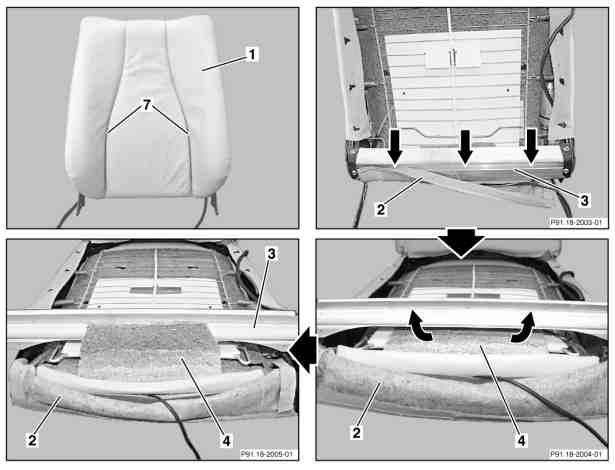
- Remove front seat backrest (1) (up to 31/08/2002). Place front seat backrest (1) with the covering (2) downwards on a suitable base.
- Remove driver's seat cushion (as of 01/09/2002).
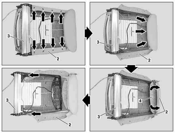
- Pull covering (2) out of the insert fold (arrows) on the bottom of the backrest frame (3)
- Pull out shackle of rubberized fiber matting (4) at bottom (arrows) on backrest frame (3)
- Unhook covering (2) all-round at the backrest frame (3) (arrows)
- Disconnect connector for backrest ventilation (with front deluxe seat, incl. heated seat and seat ventilation, code 401a).
- Remove covering (2) with rubberized fiber matting (4) from the backrest frame (3)
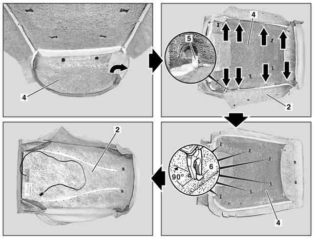
- Remove side stapling clips (5) from the stapling wires (7)
- Release stapling clips (6), to do so rotate staple clip through 90° using flat pliers
- Pull the Velcro fabric strips off the rubberized fiber matting (4)
- Pull covering (2) off the rubberized fiber matting (4) and remove
Install:
- Insert stapling clips (6) into rubberized fiber matting (4) and straighten out
- Pull covering (2) at the top over the "head" of the rubberized fiber matting (4)
- Fold upholstery (2) to side, place on rubberized fiber matting (4) and straighten out. When replacing, draw the stapling wires (7) into the fabric sleeves in the covering (2).
- Connect longitudinal stapling wires with the stapling clips (6)
- Align covering (2) with the rubberized fiber matting (4) and fix in position at the side with Velcro fabric strips
- Hook side stapling clips (5) into the stapling wires (7)
- Insert backrest frame (3) into rubberized fiber matting (4)
- Slide shackle of rubberized fiber matting (4) (arrow) at bottom into backrest frame (3)
- Insert covering (2) all way round on backrest frame (3) and at "header piece"
- Install head restraint guide on the front seat
- Install front seat backrest (up to 31/08/2002).
- Install driver seat cushion (as of 01/09/2002).
Remove/install head restraint upholstery (up to 31/08/2002)
|
|
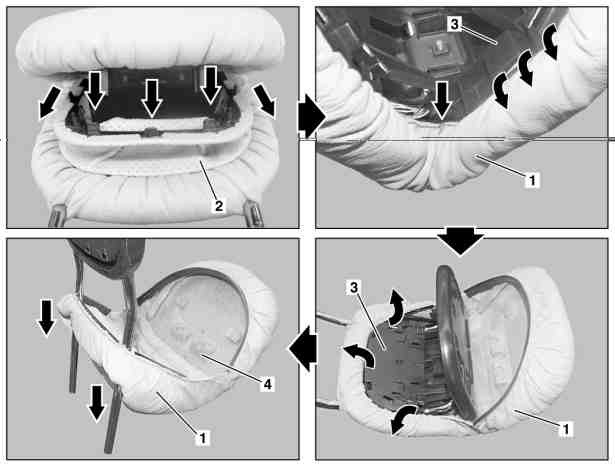
- Remove head restraint and place on suitable surface
- Completely unfold head restraint
- Remove expansion element (2). Unclip expansion element (2) at first on guide rods on opposite side, then withdraw downwards.
- Remove upholstery (1) in hinge area at left and right on housing (3)
- Remove upholstery (1) from clip groove on housing (3)
- Slide upholstery (1) on guide rods downwards and remove
- Install in the reverse order
Remove/install blower regulator for seat ventilation motors in front seat (code 401)
|
|
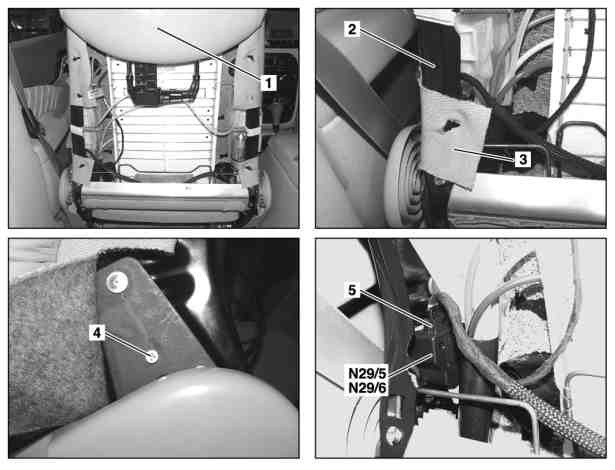
- Remove tensioning element (front seat backrest seat-back lining) from front seat backrest (1)
- Detach backrest upholstery (3) from backrest frame (2)
- Disconnect connector (5) from left (N29/5) and right (N29/6) front seat ventilators
- Unscrew bolt (4) and remove left (N29/5) and right (N29/6) front seat ventilator blower regulator
- Install in the reverse order
- Perform seat ventilation function test
Remove/install front seat cushion ventilation motors (code 401)
- Remove driver's seat cushion (1)
- Remove cover of front seat cushion
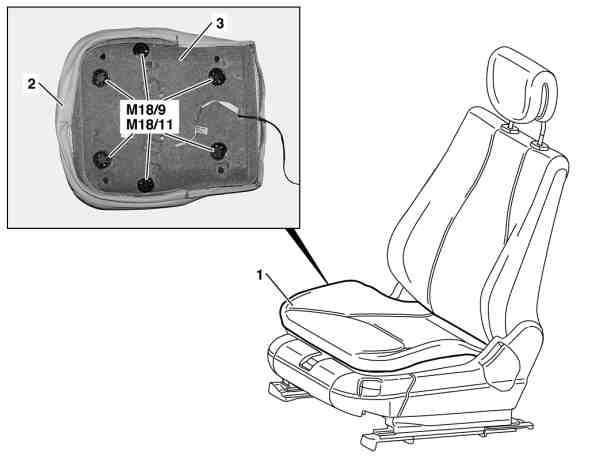
- Remove defective front left (M18/9) and right (M18/11) seat cushion ventilation motor group together with rubberized fiber matting/foam rubber (3). Individual motors are not replaced - the entire motor group with rubberized fiber matting/foam rubber (3) is replaced.
- Install in the reverse order
- Perform seat ventilation function check
