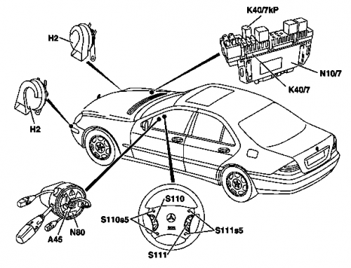
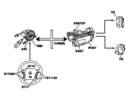
Fanfare horns
Fanfare horns, function
Function requirements
- Circuit 15: ON
Function:
- When the impact absorber on the multifunction steering wheel is pressed, one or more buttons for the fanfare horns (S110s5, S111s5) are actuated.
- The status of these buttons is read in by the steering column module (N80).
- The steering column module (N80) sends a corresponding message on the (interior) CAN.
- This message is received by the right front SAM control unit (N10/7).
- The right front SAM control unit (N10/7) actuates the relay for the fanfare horns (K40/7kP). This relay is located on the right front fuse and relay module (K40/7).
- The relay for the fanfare horns (K40/7kP) connects the two fanfare horns (H2) to circuit 30.
- The signal sounds as soon as at least one of the buttons (S110s5, S111s5) is actuated.
Actuation of the fanfare horns (H2): One line of the fanfare horns (H2) is always connected to ground, actuation is therefore accomplished by connecting to circuit 30 (via K40/7kP).
Control of the relay for the fanfare horns (K40/7kP): The relay coil for the fanfare horns (K40/7kP) is permanently connected to circuit 15; when the fanfare horns (H2) are actuated, the other connection is connected to ground via the right front SAM control unit (N10/7).
Buttons for the fanfare horns (S110s5, S111s5): Four buttons for the fanfare horns are located on a circuit board below the impact absorber of the multifunction steering wheel. This ensures that the fanfare horns can be actuated from any point on the impact absorber. The two right and the two left buttons are each connected in parallel. They are read in voltage-coded by the steering column module (N80) together with the buttons of the left and right multifunction steering wheel button groups (S110, S111). See also applicable wiring diagrams.
Fanfare horns arrangement of components
Fanfare horns interlinking of components
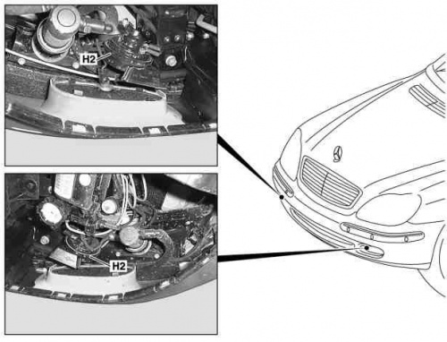
Removing and installing fanfare horns
To access and remove fanfare horns, engine compartment lining has to be removed. Two electrical connectors have to be removed by pulling them off.
|
|
Parts
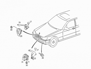
A horn set includes a high- and low-tone horn. A high-tone horn produces a more piercing sound. This enables the signal to reach forward and farther. The low-tone horn, with a lower frequency, is better heard at close range. Used together, the two horns maximize signal area coverage, ensuring better safety.

On facelift vehicles OE horns are produced by Hella. Previously, the horns used 400/500 Hz frequency. Newer horns use 420/510 Hz frequency for low- and high-tone horn.
- Front right 400 Hz - A0045428020 (replaces A0045425620)
- Front right 420 Hz - A0065421120 (replaces A0055427020)
- Front right 420 Hz - BOSCH 9320335207
- Front right 420 Hz - Topran 102955
- Front left 500 Hz - A0045428120 (replaces A0045425720)
- Front left 510 Hz - A0065421220 (replaces A0055427120)
- Front left 510 Hz - BOSCH 9320335208
- Front left 510 Hz - Topran 102956
- Set of 420/510 Hz horns - BOSCH 9320335206 (set consisting of 9320335207 and 9320335208)
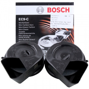
Topran and other (non-BOSCH) analogues have a bit different design and size, but can be mounted on W220.
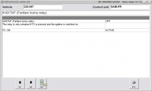
DAS actuations
 |
