Steering wheel: Difference between revisions
| Line 136: | Line 136: | ||
# Remove two screws (arrow). At the same time hold the airbag unit. | # Remove two screws (arrow). At the same time hold the airbag unit. | ||
# Lift off the airbag unit from the steering wheel and detach the plug-in connector from the squib on the gas generator. Installation: Connector must be heard to engage when being plugged in. | # Lift off the airbag unit from the steering wheel and detach the plug-in connector from the squib on the gas generator. Installation: Connector must be heard to engage when being plugged in. | ||
# Remove airbag unit from steering wheel | # Remove airbag unit from steering wheel. | ||
# Install in the reverse order. Installation: The steering wheel must always be replaced after the driver airbag unit has been triggered. | # Install in the reverse order. Installation: The steering wheel must always be replaced after the driver airbag unit has been triggered. | ||
# Check the automatic resetting of the combination switch. | # Check the automatic resetting of the combination switch. | ||
| Line 143: | Line 143: | ||
Bolt, airbag to steering wheel - 8 Nm. | Bolt, airbag to steering wheel - 8 Nm. | ||
Informative: | |||
* Risk of injury caused by performing testing or repair work on airbag or emergency tensioning retractor units. Store airbag units with deployment side facing up; do not expose to temperatures greater than 100 °C. When working on these units, disconnect the power supply. | |||
* Assessment of airbag and belt tensioner units in accident vehicles (see below). | |||
* Notes on performing repair, body work and welding on vehicles with airbags and ETR units | |||
* Legal requirements on handling and storing airbags and emergency tensioning retractor units | |||
* Notes on disposing of airbag and emergency tensioning retractor units | |||
* Make airbag units unusable | |||
====Assessment of airbag and belt tensioner units in accident vehicles==== | ====Assessment of airbag and belt tensioner units in accident vehicles==== | ||
Revision as of 23:20, 15 February 2017
Steering Wheel
 |
 |
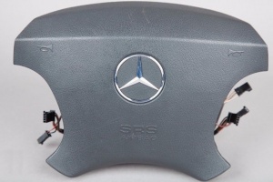
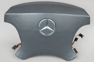
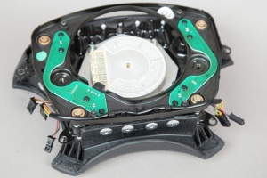
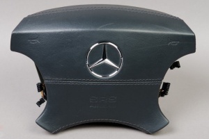
Steering Wheel Airbag
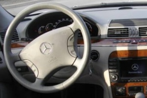
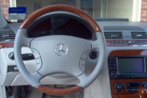
Driver's airbag is mounted in the steering wheel.
 |
 |
 |
 |
| Part No. | Notes |
|---|---|
| A2204600298 | To Date: 30/06/2000 |
| A2204600398 | From Date: 30/06/2000, To Date: 01/09/2002, Replaced by: A2204601598 |
| A2204601598 | From Date: 30/06/2000, To Date: 01/09/2002 |
| A2204602498 | From Date: 30/09/2002 |
For vehicles with option code 289 - WOOD/LEATHER STEERING-WHEEL:
| Part No. | Notes |
|---|---|
| A2204600898 | To Date: 30/06/2000 |
| A2204600998 | From Date: 30/06/2000, To Date: 01/09/2002, Replaced by: A2204601698 |
| A2204601698 | From Date: 30/06/2000, To Date: 01/09/2002 |
| A2204602598 | From Date: 30/09/2002 |
For vehicles with option code Y95 - STEERING WHEEL IN LEATHER-/DESIGNO-WOOD DESIGN:
| Part No. | Notes |
|---|---|
| A2204600898 | To Date: 30/06/2000 |
| A2204601498 | From Date: 30/06/2000, Replaced by: A2204601798 |
| A2204601798 | From Date: 30/06/2000, Replaced by: A2204602698 |
| A2204602698 | From Date: 30/06/2000 |
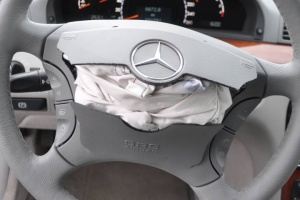
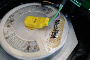
Post-deployment
 |
 |
Steering Wheel Buttons
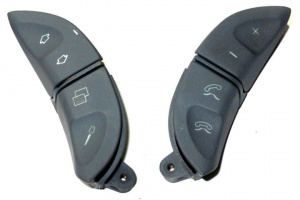
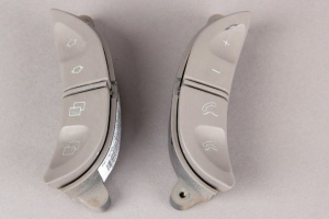
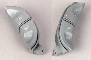
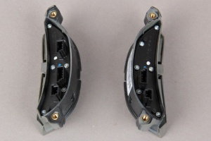
Steering wheel buttons are attached to both sides of steering wheel airbag.
 |
 |
 |
 |
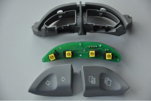 |
| Part No. | Notes |
|---|---|
| A2208207810 | To Date: 30/06/2000 |
| A2208215351 | From Date: 30/06/2000, To Date: 01/09/2002 |
| A2208210679 | From Date: 30/09/2002 |
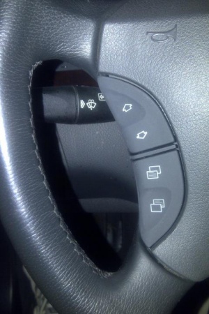
Sticky Buttons
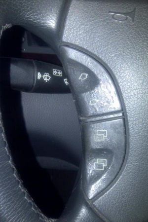
Steering wheel buttons in manufacturing phase have been covered with soft feel coating. However, when worn the soft feel coating is dissolving away and creates a sticky film on the buttons. A simple fix is to scrape off the sticky residue using finger nails. This will leave a nice smooth button. There is a subtle color tone change after the sticky layer is taken off, but it is barely noticeable.
 |
 |
There have been reports that "Goo Gone" is helpful for removing the coating. However, better try to avoid using solvents, because it is easy to scratch off the original paint also. It helps to leave the buttons in soap water (e.g., Fairy Washing Up Liquid) overnight. This will make scratching off the sticky part easier.
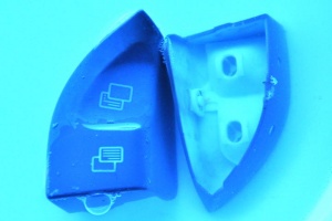
Note: Don't try to clean the plastic frame to which the buttons attach. The color layer there is much thinner and too easily comes off along with the sticky coating.
DIY
Remove/install airbag unit on the steering wheel
- Withdraw ignition key
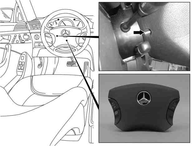
- Remove two screws (arrow). At the same time hold the airbag unit.
- Lift off the airbag unit from the steering wheel and detach the plug-in connector from the squib on the gas generator. Installation: Connector must be heard to engage when being plugged in.
- Remove airbag unit from steering wheel.
- Install in the reverse order. Installation: The steering wheel must always be replaced after the driver airbag unit has been triggered.
- Check the automatic resetting of the combination switch.
- Read out fault memory. Connect STAR DIAGNOSIS and read out fault memory.
Bolt, airbag to steering wheel - 8 Nm.
Informative:
- Risk of injury caused by performing testing or repair work on airbag or emergency tensioning retractor units. Store airbag units with deployment side facing up; do not expose to temperatures greater than 100 °C. When working on these units, disconnect the power supply.
- Assessment of airbag and belt tensioner units in accident vehicles (see below).
- Notes on performing repair, body work and welding on vehicles with airbags and ETR units
- Legal requirements on handling and storing airbags and emergency tensioning retractor units
- Notes on disposing of airbag and emergency tensioning retractor units
- Make airbag units unusable
Assessment of airbag and belt tensioner units in accident vehicles
Following an accident:
- The airbag and emergency tensioning retractor restraint system is to be checked for external damage and defects and as to whether it has been triggered
- Defective or damaged components must be immediately replaced. Repair of these components is not permitted
The restraint system control unit must be replaced:
- If the housing is deformed or otherwise damaged
- If the console is deformed; even if the restraint system control unit appears to be in good condition externally
- If there is an electrical defect
- Or after the airbag has deployed three times
A new restraint system control unit must be programmed and parameterized after installation.
The airbag or emergency tensioning retractor units must be replaced:
- Following deployment
- If there is external damage (even without deployment)
- Or if there is an electrical defect
After the driver airbag has been deployed, the steering wheel and steering column tubes with crash element must be replaced. If axial play or a noise is detected at the steering column tube, this must also be replaced, even if the airbag was not deployed.
Proper function of the steering column tube is only guaranteed if the crash element is not damaged in any manner.
The dashboard must be replaced after the front passenger airbag has deployed.
The sidebag cover in the door lining and the side paneling must be replaced after the sidebag has been deployed. Otherwise the airbag cannot be guaranteed to function correctly.
Remove/install steering wheel
|
|
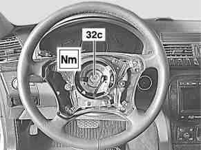
- Remove airbag unit from steering wheel (32)
- Move steering wheel (32) to horizontal position. Front wheels in straight-ahead position.
- # Remove countersunk screw (32c), steadying steering wheel (32). Installation: Replace countersunk bolt (32c).
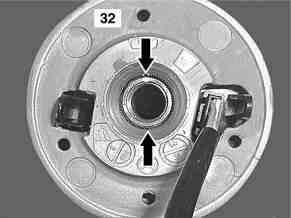
- Remove steering wheel (32). Do not pay attention to the markings on the upper steering shaft. Installation: The front wheels must be in the straight-ahead position. Fit steering wheel (32) horizontally onto steering shaft. The recesses in the splines (arrows) run vertically.
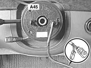
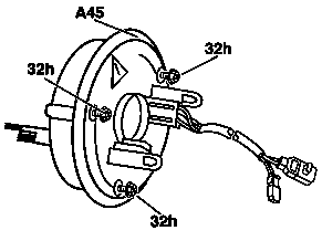
- Check fanfare horns and airbag clock spring contact (A45) for damage. When the steering wheel (32) is detached, the fanfare horns and airbag clock spring contact (A45) must not be twisted, otherwise it will be damaged. Replace damaged fanfare horns and airbag clock spring contact (A45), see: Remove/install clock spring contact.
- Install in the reverse order.
- Conduct a road test.
Tests during the road test:
- Turn signal reset - When the steering wheel is offset by more than 1 tooth, satisfactory resetting of the turn signal is no longer guaranteed.
- Airbag indicator lamp - The SRS indicator lamp must not light up on full steering lock in both directions.
- Steering wheel position (32) - If the steering wheel (32) is crooked, adjust it by max. 1 tooth.
Bolts, steering wheel to steering shaft - 80 Nm.
Remove/install clock spring contact
|
|
- Remove steering wheel
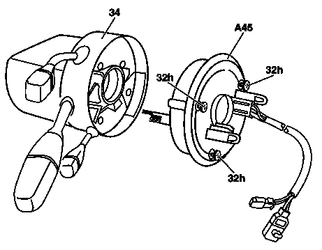
- Unscrew a mounting bolt (32h) far enough so that the fanfare horns and airbag clock spring contact (A45) cannot be twisted. The mounting bolts (32h) act as both an anti-rotation device and an assembly aid.
- Remove steering column tube switch module (34). Remove complete steering column switch module (34): Remove/install steering column module.
- Unscrew remaining mounting bolts (32h) far enough so that the fanfare horns and airbag clock spring contact (A45) detaches from the steering column switch module (34).
- Carefully remove fanfare horns and airbag clock spring contact (A45) from steering column switch module (34). Installation: If the fanfare horns and airbag clock spring contact (A45) was twisted, e.g. with steering coupling removed, the center position must be set otherwise the fanfare horns and airbag clock spring contact (A45) will be damaged: Adjust center position of clock spring contact.
- Check fanfare horns and airbag clock spring contact (A45) for damage. Do not use oil or grease, as otherwise the function of the fanfare horns and airbag clock spring contact (A45) will be impaired. Perform visual inspection and if necessary replace fanfare horns and airbag clock spring contact (A45).
- Install in the reverse order
Set the clock spring contact to center position
The center position of the fanfare horns and airbag clock spring contact (A45) is crucial
for the trouble-free function of the airbag system and signaling system. When removed this is
guaranteed by the screws (32h).
If the fanfare horns and airbag clock spring contact (A45) is nevertheless twisted, e.g. when the steering coupling is removed or when the screws are unscrewed completely (32h), the center position of the fanfare horns and airbag (A45) can be adjusted as per the following work procedure.
- Remove fanfare horns and airbag clock spring contact (A45).
- Screw the screws (32h) fully into the fanfare horns and airbag clock spring contact (A45).
- Turn the fanfare horns and airbag (A45) counterclockwise until a light resistance is detectable (the fanfare horns and airbag clock spring contact (A45) is rolled up completely).
- Turn the fanfare horns and airbag clock spring contact (A45) approx. 3 to 3.5 revolutions clockwise (turn back) until the screws (32h) can be unscrewed again through the openings and the fanfare horns and airbag clock spring contact (A45) fixed in the center position. The total adjustment range of the fanfare horns and airbag clock spring contact (A45) is 6 to 7 turns.
Remove/install steering angle sensor
|
|
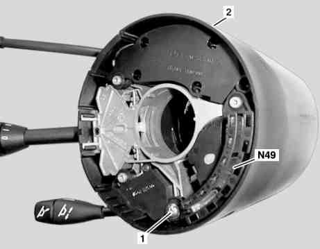
- Remove clock spring contact
- Unscrew bolt (1)
- Remove steering angle sensor (N49) from steering column module.
- Install in the reverse order
Remove/install steering column module
|
|
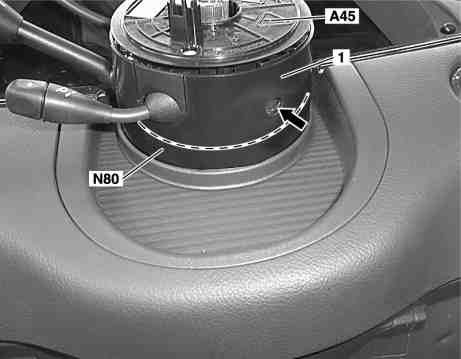
Shown on steering column switch module without voice control system
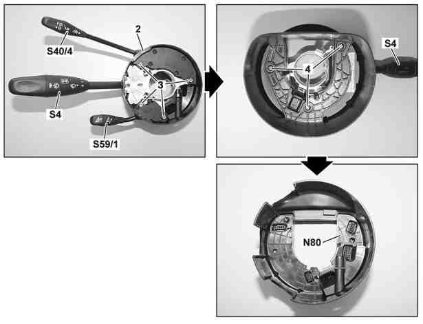
- Remove spiral contact coil (A45)
- Remove steering angle sensor
- Loosen internal Torx bolt (arrow) and remove steering column switch module (1). Internal Torx bolt (arrow) is secured to prevent it falling out.
- Remove cover (2) and remove push button (S40/4) upwards out of steering column tube switch module (1). Installation: Ensure that the studs (3) are seated cleanly in the holes, by paying attention to the guides on the push button (S40).
- Remove switch group or switch (S59/1) upwards out of the steering column tube switch module (1).
- Installation: Ensure that the studs (3) are seated cleanly in the holes, by paying attention to the guides on the switch group or switch (S59/1).
- Remove bolts (4) and remove combination switch (S4) upwards out of steering column switch module (1).
- Remove steering column module (N80) upwards out of steering column switch module (1).
- Install in the reverse order.
- After replacing steering column tube module (N80) on vehicles with code (219) Distronic (DTR) perform initialization of DTR control unit with STAR DIAGNOSIS.
