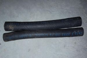
EVAP system: Difference between revisions
(→Vent valve (non-USA): fuel tank vent valve photos) |
|||
| (32 intermediate revisions by the same user not shown) | |||
| Line 6: | Line 6: | ||
A typical system consists of the fuel tank, an EVAP vapor storage canister full of charcoal, valves, hoses and a sealed fuel tank gas cap. The EVAP system is designed to stop fuel system fumes from leaking directly into the atmosphere. Vent lines from the fuel tank pass vapors to the vapor canister, where they are trapped and stored until the engine is started. When the engine is warm and the vehicle is going down the road, the PCM then opens a purge valve allowing the vapors to be drawn from the storage canister into the intake manifold. The fuel vapors are then burned in the engine along with the air/fuel mixture. | A typical system consists of the fuel tank, an EVAP vapor storage canister full of charcoal, valves, hoses and a sealed fuel tank gas cap. The EVAP system is designed to stop fuel system fumes from leaking directly into the atmosphere. Vent lines from the fuel tank pass vapors to the vapor canister, where they are trapped and stored until the engine is started. When the engine is warm and the vehicle is going down the road, the PCM then opens a purge valve allowing the vapors to be drawn from the storage canister into the intake manifold. The fuel vapors are then burned in the engine along with the air/fuel mixture. | ||
Note that due to the legal regulation in the USA, the vehicles with the option code [[Option_codes#494_-_U.S._VERSION|494 (U.S. VERSION)]] have a more advanced EVAP system providing possibility for a leakage test of the EVAP system. The main difference is that the USA vehicles have an activated charcoal canister shutoff valve to close the ventilation of the activated charcoal canister and have a [[fuel tank|fuel tank pressure sensor]] able to measure the pressure of the EVAP system. Vehicles in the rest of the world have the activated charcoal canister always open, which means that detection of gasoline vapor leaks is a manual work for these vehicles. The USA vehicles are better protected against fuel tank overfilling. In case non-USA vehicles are overfilled, the excess fuel can get into the activated charcoal canister damaging the charcoal and [[Fuel pump filter|fuel filter pressure regulator membrane]]. | |||
== Fuel evaporation control system function == | == Fuel evaporation control system function == | ||
| Line 25: | Line 26: | ||
{| | {| | ||
|[[File:W220_fuel_evaporation_control_system_1.png|400px]] | |||
| | | | ||
Shown on engine 119 | Shown on engine 119: | ||
* 75 - Fuel tank | * 75 - Fuel tank | ||
* 77 - Activated charcoal canister | * 77 - Activated charcoal canister | ||
| Line 32: | Line 34: | ||
* Y58/1 - Purge control valve | * Y58/1 - Purge control valve | ||
* a - Pressurization line | * a - Pressurization line | ||
|} | |} | ||
{| | {| | ||
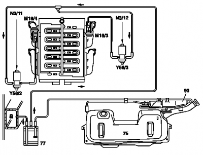
|[[File:W220_fuel_evaporation_control_system_2.png|400px]] | |||
| | | | ||
Shown on ENGINE 120 | Shown on ENGINE 120: | ||
* 75 - Fuel tank | * 75 - Fuel tank | ||
* 77 - Activated charcoal canister | * 77 - Activated charcoal canister | ||
| Line 48: | Line 50: | ||
* Y58/3 - Switchover valve Right regeneration | * Y58/3 - Switchover valve Right regeneration | ||
* a - Pressurization line | * a - Pressurization line | ||
|} | |} | ||
| Line 99: | Line 100: | ||
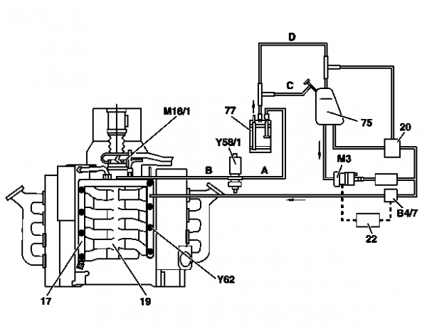
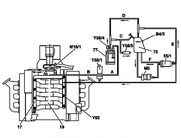
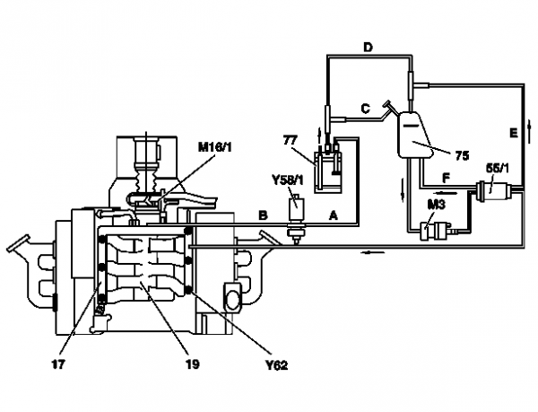
{| | {| | ||
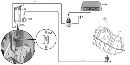
|[[File:W220_fuel_evaporation_control_system_3.png|500px]] | |||
| | | | ||
* 75 - Fuel tank | * 75 - Fuel tank | ||
| Line 110: | Line 112: | ||
* C - Line to fuel tank | * C - Line to fuel tank | ||
* D - Line to purge control valve | * D - Line to purge control valve | ||
|} | |} | ||
| Line 144: | Line 145: | ||
As of approx. 7/98 a vent valve is integrated in the vent line to the activated charcoal canister (without USA). | As of approx. 7/98 a vent valve is integrated in the vent line to the activated charcoal canister (without USA). | ||
== Fuel filler neck with cap (USA) == | == On-board refueling vapor recovery function (version USA) == | ||
=== Up to 2000/08/31 === | |||
<!-- | |||
GF47.10-P-3004A, On-board refueling vapor recovery function, 12.5.98 | |||
MODEL 129 with ENGINE 112, 113 with CODE (494a) USA version | |||
MODEL 170 up to 31.8.00 with ENGINE 111, 112 with CODE (494a) USA version | |||
MODEL 210.2 with ENGINE 112, 113 with CODE (494a) USA version | |||
MODEL 210.0 up to 31.5.01 with ENGINE 112, 113 with CODE (494a) USA version | |||
MODEL 220 up to 31.8.00 with ENGINE 112, 113, 137 with CODE (494a) USA version | |||
MODEL 215 up to 31.8.00 with ENGINE 137, 113 with CODE (494a) USA version | |||
--> | |||
{| | |||
|[[File:W220_on-board_refueling_vapor_recovery_function.jpg|750px]] | |||
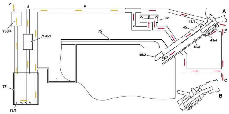
|Shown on Model 210 sedan: | |||
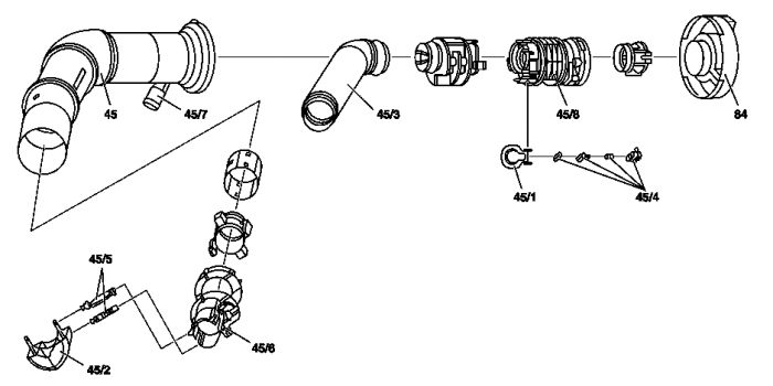
*45 - Filler neck (connection for collecting fuel vapors when refueling) | |||
*45/1 - Flap | |||
*45/2 - Float with flap | |||
*45/3 - Corrugated tube | |||
*45/4 - Pressure relief valve (in top insert integrated at corrugated tube, release pressure approx. 60 - 90 mbar) | |||
*75 - Fuel tank | |||
*77 - Activated charcoal canister | |||
*77/1 - Pressure relief valve (release pressure approx. 30 - 40 mbar) | |||
*82 - Pressure relief valve in ORVR vent line (release pressure approx. 60 - 90 mbar) | |||
*Y58/1 - Purge control valve | |||
*Y58/4 - Activated charcoal canister shutoff valve | |||
*A - Nozzle, extraction through metal tube | |||
*B - Nozzle, extraction through rubber boot (overflow not recognizable) | |||
* a - ORVR vent line (from filler neck to activated charcoal canister) | |||
* b - Hose line to pressure relief valve | |||
* c - Fuel overflow line to atmosphere | |||
* d - to engine | |||
* e - Fuel overflow line to atmosphere (to tank recess) | |||
* f - Fuel tank air admission line | |||
|} | |||
Task: | |||
* The legislator requires, that the refueling gases in the vehicle are collected (ORVR = Onboard Refueling Vapor Recovery). | |||
* Separate fuel and refueling gases to prevent fuel from flowing into the activated charcoal canister due to inappropriate refueling or a defective nozzle. | |||
* Ending refueling when the refueling nozzle switches off and the fuel tank is full! On no account overfilling fuel tank as a result of refueling nozzle being switched on several times. | |||
Function: | |||
The fuel vapors are recovered at the filler neck (45) and passed along a ventilation hose (a) to the activated charcoal canister. | |||
An insert inserted in the filler neck prevents, that when refueling fuel flows to the activated charcoal canister. | |||
To do this the fuel vapors in the filler neck are diverted several times in order to separate the gases from the fuel. | |||
The connection to the activated charcoal canister is shut off by a flap (45/1) when driving. It is opened by the gasoline pump nozzle when refueling. | |||
Additional measures if fuel tank is overfilled: | |||
* If the fuel tank is full, the float (45/2) closes with flap the filler neck below. This ensures that the refueling nozzle shuts off more rapidly and overfilling is largely prevented. | |||
* A too high level of fuel in the filler neck presses open the pressure relief valve (45/4). Fuel flows to atmosphere at the nozzle. End refueling! On nozzles fitted with rubber boot (B) this overflowing is no longer recognizable. | |||
* A too high pressure in the ORVR vent line (a) acts on the diaphragm in the pressure relief valve (82). If the diaphragm lifts off because of excessively high pressure, the pressure is released at the fuel tank recess (e) and below the wheelhouse to atmosphere (c). End refueling! | |||
* If the pressure is too high in the activated charcoal canister (77), the pressure relief valve (77/1) opens. The pressure is reduced through the activated charcoal canister shutoff valve (Y58/4) to atmosphere (c). | |||
==== Fuel filler neck with cap (version USA up to 2000/08/31) ==== | |||
<!-- GF47.10-P-3003B, Fuel filler neck with cap, location/task/design/function, 28.4.98 | <!-- GF47.10-P-3003B, Fuel filler neck with cap, location/task/design/function, 28.4.98 | ||
MODEL 129 with ENGINE 112, 113 with CODE (494a) USA version | MODEL 129 with ENGINE 112, 113 with CODE (494a) USA version | ||
| Line 178: | Line 233: | ||
When the fuel tank is full, a float closes a flap at the bottom insert. The filler neck is filled rapidly and the gasoline pump nozzle | When the fuel tank is full, a float closes a flap at the bottom insert. The filler neck is filled rapidly and the gasoline pump nozzle | ||
switches off. | switches off. | ||
==== Pressure relief valve (version USA up to 2000/08/31) ==== | |||
<!-- GF47.31-P-3100A, Pressure relief valve, location/task/design/function, 11.5.98 | |||
ENGINE 112, 113 in MODEL 129 with CODE (494a) USA version | |||
ENGINE 111, 112 in MODEL 170 up to 31.8.00 with CODE (494a) USA version | |||
ENGINE 112, 113 in MODEL 210.2 with CODE (494a) USA version | |||
ENGINE 112, 113 in MODEL 210.0 up to 31.5.01 with CODE (494a) USA version | |||
ENGINE 112, 113, 137 in MODEL 220 up to 31.8.00 with CODE (494a) USA version | |||
ENGINE 137, 113 in MODEL 215 up to 31.8.00 with CODE (494a) USA version | |||
--> | |||
{| | |||
|[[File:W220_pressure_relief_valve_design.jpg|400px]] | |||
| | |||
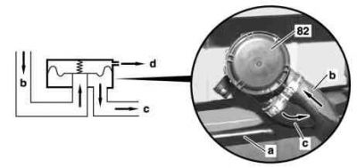
Pressure relief valve design: | |||
* 82 - Pressure relief valve | |||
* a - ORVR vent line (from filler neck to activated charcoal canister) | |||
* b - Hose line to pressure relief valve | |||
* c - Fuel overflow line to atmosphere | |||
* d - Air admission to diaphragm chamber | |||
|} | |||
The task of the pressure relief valve (also known as safety valve) is limiting the pressure in the ORVR vent line if fuel tank overfilled or if gasoline pump | |||
nozzle faulty (does not switch off). | |||
The pressure relief valve consists of a housing with internal diaphragm which seals off the line to the pressure relief valve by means of a spring. | |||
The diaphragm lifts off at a pressure of approx. 60 to 90 mbar. The fuel overflow line to atmosphere opens. Air is admitted to the diaphragm chamber. | |||
The pressure relief valve is located below rear shelf. | |||
===== Remove/install pressure relief valve ===== | |||
<!-- AR47.31-P-8022M, Removing and installing safety valve, 9.7.98 | |||
ENGINE 113.941 in MODEL 220.070 /170 with CODE (494a) USA version | |||
ENGINE 113.960 in MODEL 220.175 with CODE (494a) USA version | |||
ENGINE 113.960 in MODEL 215.375 with CODE (494a) USA version | |||
ENGINE 137.970 in MODEL 220.178, 215.378 with CODE (494a) USA version | |||
--> | |||
{| | |||
|[[File:W220_pressure_relief_safety_valve.jpg|400px]] | |||
| | |||
Shown on model 220: | |||
* 82 - Pressure relief valve | |||
* 82/1 - Fuel overflow line | |||
* 82/2 - ORVR vent line | |||
* 82/3 - Vent line | |||
* 82/4 - Hose clip | |||
|} | |||
# Remove rear shelf | |||
# Detach fuel hose of fuel overflow line (82/1) and fuel hose of vent line (82/3) at pressure relief valve (82). Replace hose clip (82/4). | |||
# Remove pressure relief valve (82). Take out complete with bracket. | |||
# Install in the reverse order | |||
=== As of 2000/09/01 === | |||
<!-- GF47.10-P-3004B, On-board refueling vapor recovery function, 6.5.98 | |||
MODEL 170 as of 1.9.00 with ENGINE 111, 112 (except , 112.96) with CODE (494) USA version | |||
MODEL 202 with ENGINE 111, 112 | |||
with CODE (494) USA version | |||
with CODE (808) Model year 1998 | |||
with CODE (809) Model year 1999 | |||
with CODE (800) Model year 2000 | |||
MODEL 203 with ENGINE 111, 112 (except , 112.96) | |||
with CODE (494) USA version up to Model Year 8 | |||
MODEL 208 with ENGINE 111, 112, 113 | |||
with CODE (494) USA version | |||
with CODE (808) Model year 1998 | |||
with CODE (809) Model year 1999 | |||
with CODE (800) Model year 2000 | |||
with CODE (801) Model year 2001 | |||
with CODE (802) Model year 2002 | |||
MODEL 209 with ENGINE 112, 113 with CODE (494) USA version | |||
MODEL 210.0 as of 1.6.01 with ENGINE 112, 113 with CODE (494) USA version | |||
MODEL 211 with ENGINE 112, 113 (except , 113.99) with CODE (494) USA version | |||
MODEL 215 as of 1.9.00 with ENGINE 113, 137, 275 (except 113.99) with CODE (494) USA version | |||
MODEL 220 as of 1.9.00 with ENGINE 112, 113, 137 (except , 113.99) with CODE (494) USA version | |||
MODEL 230 with ENGINE 112, 113 (except , 113.99) with CODE (494) USA version up to Model Year 8 | |||
--> | |||
{| | |||
|[[File:W220_on-board_refueling_vapor_recovery_function_1.jpg|600px]] | |||
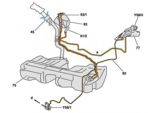
|Vehicles with low mounted fuel tank Model 202, 203, 208, 209, 211. Shown on model 202: | |||
* 45 - Filler neck (functions through its shape as a suction jet pump) | |||
* 75 - Fuel tank | |||
* 77 - Activated charcoal canister | |||
* 91/2 - Vent line (refueling vapors to expansion reservoir) | |||
* 92 - Purge line | |||
* 93 - Expansion reservoir | |||
* 93/1 - Safety valve (rollover valve) | |||
* Y58/1 - Purge control valve | |||
* Y58/4 - Activated charcoal canister shutoff valve | |||
* A - Air line from expansion reservoir to activated charcoal canister | |||
* D - to engine | |||
|} | |||
{| | |||
|[[File:W220_on-board_refueling_vapor_recovery_function_2.png|600px]] | |||
| | |||
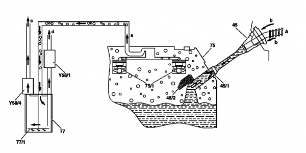
Vehicles with fuel tank in luggage compartment Model 170, 210.0, 215, 220, 230, 240: | |||
* 45 - Filler neck (functions through its shape as a suction jet pump) | |||
* 45/1 - Check valve | |||
* 45/2 - Float with flap | |||
* 75 - Fuel tank | |||
* 75/1 - Safety valve (rollover valve) | |||
* 77 - Activated charcoal canister | |||
* 77/1 - Pressure relief valve (opening pressure approx. 30 to 40 mbar) | |||
* A - Nozzle | |||
* A - ORVR vent line | |||
* B - Air intake around the nozzle | |||
* c - Depressurization in open air (if pressure relief valve 77/1 is open) | |||
* D - to engine | |||
* Y58/1 - Purge control valve | |||
* Y58/4 - Activated charcoal canister shutoff valve | |||
|} | |||
{| | |||
|[[File:W220_on-board_refueling_vapor_recovery_function_3.jpg|600px]] | |||
| | |||
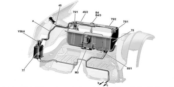
Vehicles with fuel tank in luggage compartment. Illustrated location on model 230: | |||
* 45 - Filler neck | |||
* 45/2 - Float with flap | |||
* 55/1 - Fuel filter with integrated diaphragm pressure regulator | |||
* 75 - Fuel tank | |||
* 75/1 - Safety valve (rollover valve) | |||
* 75/2 - Ventilation pipe of ORVR | |||
* 77 - Activated charcoal canister | |||
* B4 - Fuel gage sensor | |||
* B4/3 - Fuel tank pressure sensor | |||
* M3 - Fuel pump (FP) | |||
* Y58/4 - Activated charcoal canister shutoff valve | |||
* A - ORVR vent line | |||
* B - to purge control valve | |||
* c - Fuel line to engine | |||
|} | |||
The legislator demands: | |||
* Refueling gases in the vehicle must be collected (ORVR = Onboard Refueling Vapor Recovery). | |||
* Fuel and refueling gases must be separated in order to prevent fuel from flowing into the activated charcoal canister due to inappropriate refueling or a defective nozzle. | |||
The filler neck (45) is designed as a suction jet pump. | |||
The fuel out of the nozzle accelerates through this in the filler | |||
neck and air is suctioned around the nozzle. | |||
As a result of this air intake around the nozzle, the refueling | |||
vapors are not able to rise up at the filler neck and escape to | |||
atmosphere. | |||
The refueling gases are stored in the activated charcoal canister | |||
(77) and when releasing regeneration together with fuel gases out | |||
of the fuel evaporation control system, are suctioned off and burnt | |||
by engine. | |||
If fuel flows to the high mounted safety valves (75/1), they close | |||
the vent line to the activated charcoal canister. Through powerful | |||
braking, accelerating or cornering the valves can also close briefly. | |||
'''Model 202, 203, 208, 209, 211.''' | |||
The refueling vapors flow along the vent line (91/2) to the | |||
expansion reservoir and on from there to the activatetd charcoal canister. | |||
'''Model 170, 210.0, 215, 220, 230, 240.''' | |||
In the fuel tank (75), two safety valves (rollover valves) are mounted. | |||
If the fuel tank is full, the float with the flap (45/2) closes the filler | |||
neck at the bottom. This ensures that the refueling nozzle shuts off | |||
more rapidly and overfilling is largely prevented. A check valve | |||
(45/1) prevents the quick increase of fuel in the filler neck. If an | |||
excessively high pressure exists in the activated charcoal canister, | |||
the pressure relief valve (77/1) opens. In this special case the | |||
removal of pressure is performed via the activated charcoal | |||
canister shutoff valve (Y58/4) into the open air. | |||
Ending refueling when the refueling nozzle switches off (and the fuel tank is full)! | |||
On no account overfilling fuel tank as a result of refueling nozzle being switched on several times. | |||
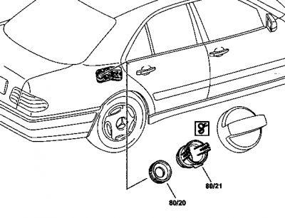
== Replacing damaged nozzle gasket in the tank filler neck (version USA) == | |||
<!-- AP47.10-P-4751A, Checking the nozzle gasket in the tank filler neck for damage and replacing it, 29.7.97 | |||
MODEL 129, 170, 210, 220 with CODE (491) U.S. version --> | |||
{| | |||
| | |||
Model 210 illustrated: | |||
* 80/20 - Nozzle gasket | |||
* 80/21 - Guide sleeve | |||
|[[File:W220_nozzle_gasket_in_filler_neck.png|400px]] | |||
|<!-- BT47.10-P-0005-01B, Guide sleeve modified --> | |||
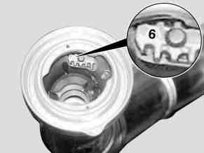
[[File:W220_guide_sleeve_modified.jpg|thumb|none|MODEL 220.### #A as of 1.1.99 with CODE (491) U.S. version: A modified guide sleeve which is identified with index (6) has been installed as of January 1999. Special tool W210589013700 is required for removing this guide sleeve.]] | |||
|} | |||
# Check the lip of the nozzle gasket (80/20) | |||
# Replace the nozzle gasket (80/20) if the lip of the nozzle (80/20) is damaged. Release the guide sleeve (80/21) using pliers (W210589013700) and take it out. | |||
== Purge system with leak test function (version USA) == | |||
<!-- | |||
GF47.30-P-3016L, Purge system with leak test function, 11.1.04 | |||
MODEL 129 as of 1.9.97 with ENGINE 104.943 /991 as of 1.8.96, 112.923 /943, 113.961, 119.982, 120.983 with CODE (494) USA version | |||
MODEL 140 with ENGINE 104.944 /994 as of 1.8.96, 119.980 /981, 120.982 with CODE (494) USA version | |||
MODEL 163 with ENGINE 112.942 /970, 113.942 /965 with CODE (494) USA version | |||
MODEL 170 with ENGINE 111.943, 111.946 as of 1.6.98, 111.973 /983, 112.947 with CODE (494) USA version | |||
MODEL 202 as of 1.10.97 with ENGINE 104.941 as of 1.8.96, 111.921 as of 1.9.98, 111.944 /945 /974, 111.975 as of 1.8.96, 112.910 /920 with CODE (494) USA version | |||
MODEL 203 with ENGINE 112.912 /946 /953 with CODE (494) USA version up to Model Year 8 | |||
MODEL 208 with ENGINE 111.944 /945 /975, 112.940, 113.943 with CODE (494) USA version | |||
MODEL 209 with ENGINE 112.912 /955, 113.968 with CODE (494) USA version | |||
MODEL 210 with ENGINE 104.995, 111.942 as of 1.9.98, 111.947, 112.911 /921 /941, 113.940, 119.985 with CODE (494) USA version | |||
MODEL 211 with ENGINE 112.913 /917 /949 /954, 113.967 /969 with CODE (494) USA version | |||
MODEL 215 with ENGINE 113.960, 137.970 with CODE (494) USA version | |||
MODEL 220 with ENGINE 112.922 /944 /972 /975, 113.941 /948 /960 /966, 137.970 with CODE (494) USA version | |||
MODEL 230 with ENGINE 112.973, 113.963 with CODE (494) USA version up to Model Year 8 | |||
--> | |||
{| | |||
|[[File:W220_purge_system_with_leak_test_function.png|500px]] | |||
| | |||
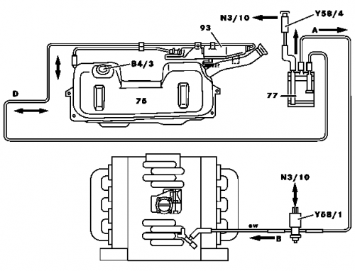
Shown on ENGINE 119: | |||
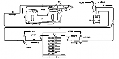
* 75 - Fuel tank | |||
* 77 - Activated charcoal canister | |||
* 93 - Fuel expansion reservoir | |||
* B4/3 - Fuel tank pressure sensor | |||
* N3/10 - Motor electronics control unit | |||
* Y58/1 - Purge control valve | |||
* Y58/4 - Activated charcoal canister shutoff valve | |||
* A - Activated charcoal canister purge control valve line | |||
* B - Lines from purge control valve to intake pipe | |||
* D - Fuel tank activated charcoal canister line | |||
|} | |||
{| | |||
|[[File:W220_purge_system_with_leak_test_function_2.png|500px]] | |||
| | |||
Shown on engine 120: | |||
* 75 - Fuel tank | |||
* 77 - Activated charcoal canister | |||
* 93 - Expansion reservoir (with optional ski bag) | |||
* Y58/2 - Left purge control valve (located on right side of engine) | |||
* Y58/3 - Right purge control valve (located on left side of engine) | |||
* Y58/4 - Activated charcoal canister shutoff valve | |||
* B4/3 - Fuel tank pressure sensor | |||
* M16/3 - Right EA/CC/ISC [EFP/TPM/LLR] actuator, positioned on left of engine | |||
* M16/4 - Left EA/CC/ISC [EFP/TPM/LLR] actuator, positioned on right of engine | |||
* N3/11 - Left ME-SFI [ME] control unit | |||
* N3/12 - Right ME-SFI [ME] control unit | |||
* A - Activated charcoal canister purge control valve line | |||
* B - Lines from the purge control valve to the EA/CC/ISC [EFP/TPM/LLR] actuator | |||
* D - Line from vent valve to activated charcoal canister | |||
|} | |||
{| | |||
|[[File:W220_purge_system_with_leak_test_function_3.jpg|500px]] | |||
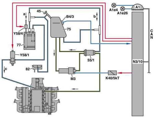
|Shown on engine 137: | |||
* 45 - Filler neck with connection for on-board refueling vapor recovery (ORVR) | |||
* 55/1 - Fuel filter with integrated fuel pressure regulator | |||
* 75 - Fuel tank | |||
* 77 - Activated charcoal canister | |||
* 82 - Pressure relief valve (ORVR) up to 08/2000 | |||
* K40/5kT - Fuel pump relay module | |||
* M3 - Fuel pump (FP) | |||
* N3/10 - Motor electronics control unit | |||
* Y58/1 - Purge control valve | |||
* Y58/4 - Activated charcoal canister shutoff valve | |||
* A1 - Instrument cluster | |||
* A1E4 - Fuel reserve indicator lamp | |||
* A1E26 - "CHECK ENGINE" MIL | |||
* B4/3 - Fuel tank pressure sensor | |||
* A - Air admission of activated charcoal canister | |||
* B - Air admission to fuel tank and fuel pressure regulator | |||
* c - Intake pipe vacuum | |||
* CAN - Data bus | |||
|} | |||
The US legislature (USA) requires that no fuel vapors are released into the atmosphere. | |||
The leak test of the fuel evaporation control system must be able to detect leaks with a diameter of approximately 1 mm and above, | |||
and from the model year 2000, leaks with a diameter of approximately 0.5 mm and above. | |||
The leak test (function chain) takes place in three stages (if the prerequisites for testing have been fulfilled): | |||
* Test for major leaks | |||
* Test for a minor leak (equal to or greater than 1 mm) | |||
* Test for a very fine leak (equal to or greater than 0.5 mm) | |||
'''Test for major leaks.''' | |||
The activated charcoal canister shut-off valve (Y58/4) is closed and the purge control valve (Y58/1) opened. | |||
The vacuum in the intake manifold (c) reaches the fuel tank (75). | |||
As a result, a vacuum builds up in the fuel tank. | |||
This is detected by the fuel tank pressure sensor (B4/3). | |||
If there is no vacuum build-up in the fuel tank (around - 6 mbar within about 12 seconds), there is a major leak (e.g. filler cap open, loose hose line). | |||
The diagnosis is aborted and the "major leak" fault is stored. | |||
If the motor electronics control unit (N3/10) detects a system with a substantial major leak, | |||
the fuel reserve indicator lamp (A1e4) in the instrument cluster (A1) blinks, | |||
or the message "CHECK FILLER CAP" appears in the multifunction display. | |||
'''Test for a minor leak.''' | |||
The purge control valve (Y58/1) is closed once a certain vacuum exists (approx. - -6 mbar). The system is now likewise closed. | |||
Finally the vacuum is evaluated for approx. 30 seconds. | |||
It must not drop any faster than 0.3 to 0.5 mbar per second (depending on the level of fuel in the tank). | |||
If the vacuum drops more rapidly, there is a minor leak. The "minor leak" fault is stored. | |||
'''Test for micro leak (not engine 137.970).''' | |||
If no minor leak has been detected, the purge system is briefly enabled and a vacuum of approx. - 6 mbar is built up again. | |||
The vacuum must not drop any faster than 0.1 to 0.15 mbar per second for a closed system (depending on the level of fuel in the tank). | |||
If the vacuum builds up more rapidly, the "micro leak" fault is stored. | |||
The reduction in the vacuum depends on the level in the fuel tank and on the degassing of the fuel. | |||
Degassing of the fuel is measured for a short time prior to the test and is allowed for in the fault statement. | |||
No test is conducted during the driving cycle if the fuel tank is filled to less than 1/4. | |||
The activated charcoal canister shut-off valve (Y58/4) is reopened after the tests have been conducted. | |||
'''Test requirements:''' | |||
* Engine at idling speed | |||
* Vehicle stationary | |||
* Blocking time after starting the engine has expired (around 16 minutes) or Mixture adaptation is complete | |||
* Lambda control enabled | |||
* Intake air temperature less than +45 °C | |||
* Coolant temperature at engine start less than +100 °C | |||
* engine 112, 113: driving position D or R engaged | |||
* Secondary air injection not active | |||
* Air pressure more than around 780 hPa (i.e. above a height of approximately 2500 m, there is no test) | |||
* Low loading of activated charcoal canister | |||
* Fuel level in fuel tank between approx. 1/4 and 3/4 | |||
* No fault in activated charcoal canister shut-off valve | |||
* No fault in the fuel tank pressure sensor | |||
* No fault in the purge control valve | |||
* Battery voltage higher than 11 V | |||
* No leak in the pressure relief valve (ORVR) | |||
'''Testing:''' | |||
* The test for "minor and micro leaks" is aborted if, during the vacuum build-up, a very high lean correction of the lambda control is performed. | |||
* The purge control valve (Y58/1) is simultaneously checked for its functioning by actuating it. If the closed valve jams, the "major leak" fault is stored. | |||
* In engine 120, there are two purge control valves. (Y58/2, Y58/3) These are actuated alternatively. | |||
* If no leakage for the "major leak" fault is found (there is a clear hissing sound in case of a leak greater than 3 mm), replace the fuel tank pressure sensor (B4/3). The fuel tank pressure sensor can be defective in such a manner that the signal is constant, but still plausible. (Sensor hangs). | |||
* If, due to a detective fuel level sensor, the fill level is implausible, the tests are not stopped. | |||
== Purge control valve actuation function == | == Purge control valve actuation function == | ||
| Line 304: | Line 691: | ||
|} | |} | ||
=== Activated charcoal canister shutoff valve (USA) === | === Activated charcoal canister shutoff valve (version USA) === | ||
<!-- | <!-- | ||
GF47.30-P-4033L, Activated charcoal canister shutoff valve location/task/design/function, 10.7.96 | GF47.30-P-4033L, Activated charcoal canister shutoff valve location/task/design/function, 10.7.96 | ||
| Line 323: | Line 710: | ||
{| | {| | ||
|[[File:W220_activated_charcoal_canister_shutoff_valve.png|400px]] | |||
| | | | ||
Shown in the design of model 210: | Shown in the design of model 210: | ||
* 77 - Activated charcoal canister | * 77 - Activated charcoal canister | ||
* Y58/4 - Activated charcoal canister shutoff valve | * Y58/4 - Activated charcoal canister shutoff valve | ||
* | * a - Ventilation via the shutoff valve | ||
* | * b - Ventilation via the safety valve | ||
|} | |} | ||
| Line 336: | Line 723: | ||
The shutoff valve contains a solenoid which closes the valve when energizing. Additionally a mechanical safety valve is installed. | The shutoff valve contains a solenoid which closes the valve when energizing. Additionally a mechanical safety valve is installed. | ||
<!-- GF47.30-P-4033-01M, Activated charcoal canister shutoff valve position --> | |||
The shutoff valve is located on the top at the vent connection of the activated charcoal canister. | The shutoff valve is located on the top at the vent connection of the activated charcoal canister. | ||
<!-- | |||
==== Remove/install shutoff valve ==== | |||
<!-- AR47.31-P-8023M, Removing, installing shutoff valve, 9.7.98 | |||
ENGINE 113.941 in MODEL 220.070 /170 with CODE (494a) USA version | |||
ENGINE 113.960 in MODEL 220.175 with CODE (494a) USA version | |||
ENGINE 113.960 in MODEL 215.375 with CODE (494a) USA version | |||
ENGINE 137.970 in MODEL 220.178, 215.378 with CODE (494a) USA version | |||
--> | |||
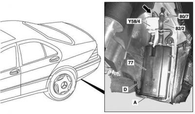
{| | |||
|[[File:W220_activated_charcoal_canister_with_orvr_location.jpg|450px]] | |||
| | |||
Shown on model 220: | |||
* 77 - Activated charcoal canister | |||
* 80/7 - Plastic nuts | |||
* 82/4 - Hose clip | |||
* Y58/4 - Shutoff valve | |||
* Arrow - Connector | |||
|} | |||
# Remove rear left wheelhousing liner | |||
# Detach connector (Arrow) | |||
# Unscrew plastic nuts (80/7) | |||
# Replace hose clip (82/4) | |||
# Take out shutoff valve (Y58/4) | |||
=== Remove/install activated charcoal canister === | |||
<!-- | |||
AR47.30-P-8212I, Remove/ install activated charcoal canister, 1.12.97 | |||
MODEL 215.373 /374 /375 /376 /378 /379, 220.063 /065 /067 /070 /073 /074 /075 /083 /084 /087 /165 /167 /170 /173 /174 /175 /176 | |||
/178 /179 /183 /184 /187 except CODE (494a) USA version | |||
--> | |||
{| | |||
|[[File:W220_remove_install_activated_charcoal_canister.jpg|400px]] | |||
| | |||
Shown on MODEL 220 | |||
* 77 - Activated charcoal canister | |||
* A - Activated charcoal canister purge control valve line | |||
* D - Vent valve line from activated charcoal canister to fuel tank | |||
|} | |||
# Raise vehicle. | |||
# Remove rear left wheelhousing liner | |||
# Detach activated charcoal canister - purge control valve line (A) and vent valve line - activated charcoal canister to fuel tank (D) at activated charcoal canister (77) | |||
# Remove activated charcoal canister (77). Lift up and out. | |||
# Install in the reverse order | |||
{| | |||
|[[File:W220_activated_charcoal_canister_installed.jpg|thumb|none|Activated charcoal canister installed]] | |||
|[[File:W220_activated_charcoal_canister_removed.jpg|thumb|none|Activated charcoal canister removed]] | |||
|[[File:W220_activated_charcoal_canister_reinstalled.jpg|thumb|none|Activated charcoal canister reinstalled]] | |||
|} | |||
=== Remove/install activated charcoal canister (version USA) === | |||
<!-- AR47.30-P-8212M, Remove/ install activated charcoal canister, 10.7.98 | |||
MODEL 215.373 /374 /375 /376 /378 /379, 220.063 /065 /067 /070 /075 /083 /084 /087 /165 /167 /170 /175 /176 /178 /179 | |||
/183 /184 /187 with CODE (494a) USA version | |||
--> | |||
{| | {| | ||
|[[File:W220_remove_install_activated_charcoal_canister_version_USA.jpg|400px]] | |||
| | | | ||
Shown on MODEL 220: | |||
* 77 - Activated charcoal canister | * 77 - Activated charcoal canister | ||
* 80/7 - Plastic nuts | * 80/7 - Plastic nuts | ||
* 82/ | * 82/2 - ORVR vent line | ||
* A - Activated charcoal canister - purge control valve line | |||
* D - Fuel tank activated charcoal canister line | |||
* Arrow - Connector | |||
* Y58/4 - Activated charcoal canister shutoff valve | * Y58/4 - Activated charcoal canister shutoff valve | ||
|} | |} | ||
# Lift rear. Remove inner fender from rear fender. | |||
# Detach lines at activated charcoal canister (77) | |||
# Unplug plug socket (arrow) at shutoff valve | |||
# Unscrew plastic nuts (80/7) | |||
# Remove activated charcoal canister (77). Lift up and out. | |||
# Install in the reverse order | |||
== Purge control valve == | == Purge control valve == | ||
| Line 386: | Line 845: | ||
* B - to intake manifold | * B - to intake manifold | ||
|[[File:W220_purge_control_valve.jpg|250px]] | |[[File:W220_purge_control_valve.jpg|250px]] | ||
|[[File:W220_purge_control_valve_A0004703693.jpg|thumb|none|Purge control valve A0004703693]] | |||
|} | |} | ||
| Line 391: | Line 851: | ||
The voltage supply to the purge control valve is performed by terminal 87. | The voltage supply to the purge control valve is performed by terminal 87. | ||
''The purge valve makes clicking noises in normal operation, they do sometimes seem to get louder as they age.'' | |||
<!-- GF47.30-P-4030-01L, Purge control valve position --> | <!-- GF47.30-P-4030-01L, Purge control valve position --> | ||
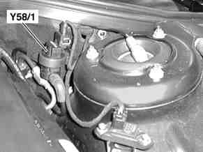
| Line 398: | Line 860: | ||
* Y58/1 - Purge control valve | * Y58/1 - Purge control valve | ||
|[[File:W220_purge_control_valve_location.jpg|300px]] | |[[File:W220_purge_control_valve_location.jpg|300px]] | ||
|[[File:W220_purge_control_valve_installed.jpg|340px]] | |||
|} | |} | ||
== Vent valve == | == Vent valve (non-USA) == | ||
<!-- GF47.30-P-3101D, Vent valve, location/task/design/function, 15.5.98 | <!-- GF47.30-P-3101D, Vent valve, location/task/design/function, 15.5.98 | ||
MODEL 129 as of 1.4.98 with ENGINE 112, 113, 120 except CODE (494) USA version | MODEL 129 as of 1.4.98 with ENGINE 112, 113, 120 except CODE (494) USA version | ||
| Line 441: | Line 905: | ||
* B - Connection to fuel tank | * B - Connection to fuel tank | ||
|[[File:W220_vent_valve_design.png|300px]] | |[[File:W220_vent_valve_design.png|300px]] | ||
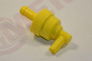
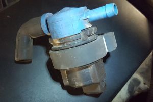
|[[File:W220_fuel_tank_vent_valve_A0004702993.jpg|thumb|none|Fuel tank vent valve A0004702993]] | |||
|} | |} | ||
| Line 452: | Line 917: | ||
The opening pressure of the vent valve (4) of approx. 30 up to 50 mbar is not achieved if the fuel tank cap is removed. | The opening pressure of the vent valve (4) of approx. 30 up to 50 mbar is not achieved if the fuel tank cap is removed. | ||
The vent line to the activated charcoal canister remains closed off. This switches off the nozzle more rapidly. | The vent line to the activated charcoal canister remains closed off. This switches off the nozzle more rapidly. | ||
{| | |||
|[[File:W220_fuel_tank_vent_valve.jpg|thumb|none|Fuel tank vent valve installed]] | |||
|[[File:W220_fuel_tank_vent_valve_unplugged.jpg|thumb|none|Fuel tank vent valve unplugged]] | |||
[[File: | |} | ||
== Connection diagram for evaporative emission control system (M113) == | == Connection diagram for evaporative emission control system (M113) == | ||
| Line 526: | Line 991: | ||
|} | |} | ||
== | == Parts == | ||
[[File:W220_fuel_evaporation_control_system.png|thumb|none|EVAP system related parts in [[EPC]]]] | |||
Identifying the components in this diagram with same nomenclature as above: | |||
{| class="wikitable" | |||
! Part | |||
! Part no. | |||
! Image | |||
! Description | |||
|- | |||
|30 | |||
|A2204700659 / A0004700159 (60 EUR) | |||
|[[File:W220_activated_charcoal_canistger_A2204700659.jpg|300px]] | |||
|Activated charcoal canister | |||
|- | |||
|40 | |||
|A0004763726 | |||
|[[File:W220_activated_charcoal_canister_hoses_A0004763726_A2024763827.jpg|300px]] | |||
|Activated charcoal canister purge line to engine. Order by the meter. 11.5x3mm 12.5cm | |||
|- | |||
|235 | |||
|A2024763827 | |||
|[[File:W220_activated_charcoal_canister_hoses_A0004763726_A2024763827.jpg|300px]] | |||
|Activated charcoal canister breather line to fuel tank. 13.2cm | |||
|} | |||
== Issues == | |||
=== Fuel in activated charcoal canister === | |||
In normal operation, no fuel should get into activated charcoal canister as it is supposed to store only fuel vapors. | |||
Fuel may get into activated charcoal canister: | |||
* From [[fuel tank]] if the fuel tank is overfilled. | |||
* From [[Fuel pump filter|fuel filter]] if the fuel pressure regulation membrane in the filter is leaking. | |||
In case fuel gets into the activated charcoal canister, the canister and as well as the fuel filter should be replaced, because the fuel from the canister might have gotten into the membrane vent valve of the fuel filter and damaged it (or shortened its life). | |||
If fuel is in the activated charcoal canister: | |||
* The engine may run rough and stall, because when the ECU purges the fuel "fumes" into engine, it actually gets raw fuel into intake and that causes the engine to sputter. | |||
* The charcoal canister is the only method the fuel tank has of breathing in to fill the void left as the fuel is pumped out. Should it become saturated, the tank will be unable to breath in, the pump will struggle, the car may stall, and the pump may experience premature failure. In some cases the fuel tank can even deform due to the excessive vacuum buildup. | |||
{| | |||
|[[File:W220_activated_charcoal_canister_leaking_fuel_1.jpg|thumb|none|Fuel leak behind rear left wheel]] | |||
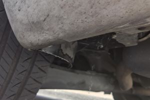
|[[File:W220_activated_charcoal_canister_leaking_fuel_2.jpg|thumb|none|Fuel leak at the rear left wheelhouse]] | |||
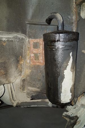
|[[File:W220_activated_charcoal_canister_leaking_fuel_3.jpg|thumb|none|Activated charcoal canister leaking fuel]] | |||
|} | |||
==== Replacing activated charcoal ==== | |||
When fuel gets into an activated charcoal, the charcoal will become saturated and will be able to adsorb only very little amount of fuel vapors. To some extent the charcoal can be regenerated by burning off the fuel, but it is best to replace charcoal with new activated charcoal. | |||
The original W220 activated charcoal canister is filled up with 1 liter of cylindrically-shaped activated charcoal pallets that are 2mm in diameter. | |||
The canister is fully serviceable - it is possible to dismantle it, wash the filters and replace the charcoal. | |||
<!-- https://www.thesamba.com/vw/forum/viewtopic.php?t=683604 --> | |||
In general, any type of activated charcoal will likely do the job, however, there are a few nuances. | |||
Activated charcoal (carbon) is available in different shapes and sizes with different adsorption characteristics. | |||
The size affects both the surface area and loss of flow through the carbon. | |||
Fish tank carbon should work as well, just that it is optimized for liquid filtering and not filtering of gas vapors. | |||
Almost all water filtration carbon is made from bituminous coal, while almost all gas adsorption charcoal is made from coco carbon or wood based carbon. | |||
The simplest way to get new activated charcoal suitable for gas is to buy some cheap activated charcoal canister and remove charcoal from it. | |||
The cheapest canister we found is Topran 111022 canister (12 EUR) made for Volkswagen (original part number 1H0201801C). | |||
The canister contains approximately 0.75 liters of charcoal of granular shape. | |||
If needed, the longer spring from Topran 111022 canister can be used for W220 canister to ensure | |||
that the new charcoal (which is slightly less in volume) does not move around inside the canister. | |||
{| | |||
|[[File:W220_A2204700659_activated_charcoal_canister_with_charcoal_removed.jpg|thumb|none|W220 canister with charcoal removed]] | |||
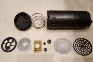
|[[File:W220_A2204700659_activated_charcoal_canister_dismantled.jpg|thumb|none|W220 canister fully dismantled]] | |||
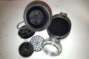
|[[File:W220_topran_111022_activated_charcoal_canister_dismantled.jpg|thumb|none|Topran 111022 canister for VW dismantled]] | |||
|[[File:W220_A2204700659_activated_charcoal_canister_charcoal_replaced.jpg|thumb|none|W220 canister with charcoal from Topran canister]] | |||
|} | |||
=== Leak testing === | |||
{| | {| | ||
| | |{{#ev:youtube|https://www.youtube.com/watch?v=GhKv5ZC_FnQ|320|center|Fuel Tank Pressure Vent Valve , Evap Canister Solenoid / Leak Test|frame}} | ||
| | |||
|} | |} | ||
=== DAS menus === | |||
The "Actuations" menu under [[DAS]] can be used to manually activate the purge control valve (Y58/1). | |||
The "Actual values" menu under [[DAS]] can be used to observe whether and to what extent (in percents) the purge control valve is actuated when the engine is running. | |||
{| | |||
|[[File:W220_DAS_actuation_purge_control_valve.png|thumb|none|ME-SFI 2.8 - Actuations - Y58/1 (Purge control valve)]] | |||
|[[File:W220_DAS_test_values_at_idle_speed.png|thumb|none|ME-SFI 2.8 - Actual values - Test engine at idle speed.]] | |||
|} | |||
Latest revision as of 01:36, 26 November 2021
The Evaporative Emission Control System (EVAP) is used to prevent gasoline vapors from escaping into the atmosphere from the fuel tank and fuel system at all times.
A typical system consists of the fuel tank, an EVAP vapor storage canister full of charcoal, valves, hoses and a sealed fuel tank gas cap. The EVAP system is designed to stop fuel system fumes from leaking directly into the atmosphere. Vent lines from the fuel tank pass vapors to the vapor canister, where they are trapped and stored until the engine is started. When the engine is warm and the vehicle is going down the road, the PCM then opens a purge valve allowing the vapors to be drawn from the storage canister into the intake manifold. The fuel vapors are then burned in the engine along with the air/fuel mixture.
Note that due to the legal regulation in the USA, the vehicles with the option code 494 (U.S. VERSION) have a more advanced EVAP system providing possibility for a leakage test of the EVAP system. The main difference is that the USA vehicles have an activated charcoal canister shutoff valve to close the ventilation of the activated charcoal canister and have a fuel tank pressure sensor able to measure the pressure of the EVAP system. Vehicles in the rest of the world have the activated charcoal canister always open, which means that detection of gasoline vapor leaks is a manual work for these vehicles. The USA vehicles are better protected against fuel tank overfilling. In case non-USA vehicles are overfilled, the excess fuel can get into the activated charcoal canister damaging the charcoal and fuel filter pressure regulator membrane.
Fuel evaporation control system function
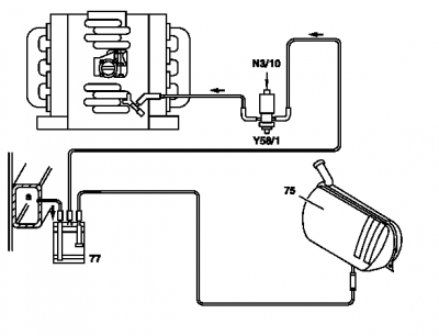
|
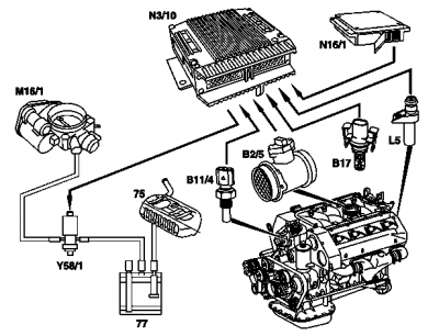
Shown on engine 119:
|
The fuel evaporation control system prevents fuel vapors escaping to atmosphere. This is done by storing the fuel vapors temporarily in the activated charcoal canister.
When the engine is running, the fuel vapors stored in the activated charcoal canister are drawn off through the purge control valve and combusted in the engine. The activated charcoal canister is purged (re-generated) at:
- Coolant temperature > 70 °C
- Blocking time after engine start elapsed, approx. 2 minutes
- Engine not in deceleration mode
The purge quantity is controlled by the ME-SFI control unit operating the purge control valve. The purge quantity is determined by constantly opening and closing the purge control valve for on and off periods of various lengths.
The idle speed control prevents changes in engine speed resulting from purging. A richer or leaner fuel-air mixture is produced in line with the charge of the activated charcoal canister with fuel vapors.
Air admission to fuel tank. Air is admitted through the activated charcoal canister. This is done through the activated charcoal canister, whereby air is drawn out of the vent/breather line or fuel vapors are drawn from the activated charcoal canister into the fuel tank.
Air release from fuel tank. The fuel tank is vented through the activated charcoal canister. The fuel vapors flow to the activated charcoal canister, where they are stored or drawn into the intake manifold in case of simultaneous regeneration.
Vent valve. On vehicles fitted with a vent valve the fuel tank is vented from a pressure of 30 to 50 mbar, and air admitted at a vacuum of 1 to 16 mbar. In addition, this prevents overfilling the fuel tank.
USA as of MY 98. During refueling the fuel vapors are collected at the filler neck and passed to the activated charcoal filter (ORVR = Onboard Refueling Vapor Recovery). Large activated charcoal canister.
Engines with charging (compressor or turbocharger). A check valve in the purge line prevents the boost pressure building up toward the activated charcoal canister.
Model 215 from chassis no. A046659 (approx. 23.3.05), without USA and model 220 from chassis no. 469233 (ca. 23.3.05), without USA with ski bag (Code 282) or cooling compartment in rear backrest (Code 308) or with retrofitted additional vent valve (76/1):
The additional vent valve (76/1) prevents the vacuum from the intake manifold passing over the activated charcoal canister through to the fuel tank for enabled purging. For this purpose, the valve closes as soon as a membrane is pressurized with vacuum pressure from the activated charcoal canister. If excess pressure or vacuum pressure affects the other valve connection, it opens immediately. This means aeration/venting of the fuel tank is then possible in an unlimited fashion via the standard vent valve (76).
Pay attention to the installation position of the vent valve (76/1). Check aeration at the activated charcoal canister for contamination (e.g. dust, spider's webs).
Fuel tank ventilation system
Shown on model 210.0 without ski bag (through-loading feature):
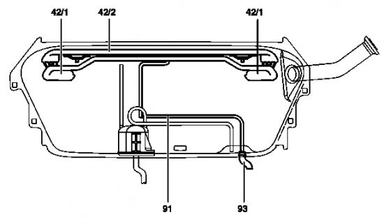
Function. The ventilation system consists of a central pipe (42/2) with an interruption vessel (42/1) at each end. The interruption vessels prevent fuel escaping along the vent line. The vent line (91) runs from the central pipe to the vent hose (93). On vehicles fitted with a gasoline engine, the vent hose (93) runs to the activated charcoal canister. As of approx. 7/98 a vent valve is integrated in the vent line to the activated charcoal canister (without USA).
On-board refueling vapor recovery function (version USA)
Up to 2000/08/31
Task:
- The legislator requires, that the refueling gases in the vehicle are collected (ORVR = Onboard Refueling Vapor Recovery).
- Separate fuel and refueling gases to prevent fuel from flowing into the activated charcoal canister due to inappropriate refueling or a defective nozzle.
- Ending refueling when the refueling nozzle switches off and the fuel tank is full! On no account overfilling fuel tank as a result of refueling nozzle being switched on several times.
Function: The fuel vapors are recovered at the filler neck (45) and passed along a ventilation hose (a) to the activated charcoal canister. An insert inserted in the filler neck prevents, that when refueling fuel flows to the activated charcoal canister. To do this the fuel vapors in the filler neck are diverted several times in order to separate the gases from the fuel. The connection to the activated charcoal canister is shut off by a flap (45/1) when driving. It is opened by the gasoline pump nozzle when refueling.
Additional measures if fuel tank is overfilled:
- If the fuel tank is full, the float (45/2) closes with flap the filler neck below. This ensures that the refueling nozzle shuts off more rapidly and overfilling is largely prevented.
- A too high level of fuel in the filler neck presses open the pressure relief valve (45/4). Fuel flows to atmosphere at the nozzle. End refueling! On nozzles fitted with rubber boot (B) this overflowing is no longer recognizable.
- A too high pressure in the ORVR vent line (a) acts on the diaphragm in the pressure relief valve (82). If the diaphragm lifts off because of excessively high pressure, the pressure is released at the fuel tank recess (e) and below the wheelhouse to atmosphere (c). End refueling!
- If the pressure is too high in the activated charcoal canister (77), the pressure relief valve (77/1) opens. The pressure is reduced through the activated charcoal canister shutoff valve (Y58/4) to atmosphere (c).
Fuel filler neck with cap (version USA up to 2000/08/31)
The fuel filler neck (45) runs through the right, rear wheelhousing to the fuel tank. It has an inserted insert and connection for collecting fuel vapors when refueling. The insert which is inserted in the filler neck prevents, that fuel flows to the activated charcoal canister due to inappropriate refueling.
The fuel vapors in the filler neck are diverted several times in order to separate the gases from the fuel. The connection to the activated charcoal canister is shut off by a flap (45/1) when driving by means of the top insert. It is opened by the gasoline pump nozzle when refueling. When the fuel tank is full, a float closes a flap at the bottom insert. The filler neck is filled rapidly and the gasoline pump nozzle switches off.
Pressure relief valve (version USA up to 2000/08/31)
The task of the pressure relief valve (also known as safety valve) is limiting the pressure in the ORVR vent line if fuel tank overfilled or if gasoline pump nozzle faulty (does not switch off).
The pressure relief valve consists of a housing with internal diaphragm which seals off the line to the pressure relief valve by means of a spring.
The diaphragm lifts off at a pressure of approx. 60 to 90 mbar. The fuel overflow line to atmosphere opens. Air is admitted to the diaphragm chamber.
The pressure relief valve is located below rear shelf.
Remove/install pressure relief valve
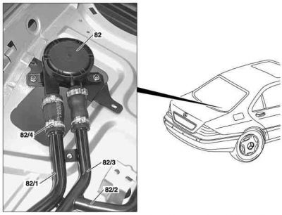
|
Shown on model 220:
|
- Remove rear shelf
- Detach fuel hose of fuel overflow line (82/1) and fuel hose of vent line (82/3) at pressure relief valve (82). Replace hose clip (82/4).
- Remove pressure relief valve (82). Take out complete with bracket.
- Install in the reverse order
As of 2000/09/01
The legislator demands:
- Refueling gases in the vehicle must be collected (ORVR = Onboard Refueling Vapor Recovery).
- Fuel and refueling gases must be separated in order to prevent fuel from flowing into the activated charcoal canister due to inappropriate refueling or a defective nozzle.
The filler neck (45) is designed as a suction jet pump. The fuel out of the nozzle accelerates through this in the filler neck and air is suctioned around the nozzle. As a result of this air intake around the nozzle, the refueling vapors are not able to rise up at the filler neck and escape to atmosphere.
The refueling gases are stored in the activated charcoal canister (77) and when releasing regeneration together with fuel gases out of the fuel evaporation control system, are suctioned off and burnt by engine.
If fuel flows to the high mounted safety valves (75/1), they close the vent line to the activated charcoal canister. Through powerful braking, accelerating or cornering the valves can also close briefly.
Model 202, 203, 208, 209, 211. The refueling vapors flow along the vent line (91/2) to the expansion reservoir and on from there to the activatetd charcoal canister.
Model 170, 210.0, 215, 220, 230, 240. In the fuel tank (75), two safety valves (rollover valves) are mounted. If the fuel tank is full, the float with the flap (45/2) closes the filler neck at the bottom. This ensures that the refueling nozzle shuts off more rapidly and overfilling is largely prevented. A check valve (45/1) prevents the quick increase of fuel in the filler neck. If an excessively high pressure exists in the activated charcoal canister, the pressure relief valve (77/1) opens. In this special case the removal of pressure is performed via the activated charcoal canister shutoff valve (Y58/4) into the open air.
Ending refueling when the refueling nozzle switches off (and the fuel tank is full)! On no account overfilling fuel tank as a result of refueling nozzle being switched on several times.
Replacing damaged nozzle gasket in the tank filler neck (version USA)
- Check the lip of the nozzle gasket (80/20)
- Replace the nozzle gasket (80/20) if the lip of the nozzle (80/20) is damaged. Release the guide sleeve (80/21) using pliers (W210589013700) and take it out.
Purge system with leak test function (version USA)
The US legislature (USA) requires that no fuel vapors are released into the atmosphere. The leak test of the fuel evaporation control system must be able to detect leaks with a diameter of approximately 1 mm and above, and from the model year 2000, leaks with a diameter of approximately 0.5 mm and above.
The leak test (function chain) takes place in three stages (if the prerequisites for testing have been fulfilled):
- Test for major leaks
- Test for a minor leak (equal to or greater than 1 mm)
- Test for a very fine leak (equal to or greater than 0.5 mm)
Test for major leaks. The activated charcoal canister shut-off valve (Y58/4) is closed and the purge control valve (Y58/1) opened. The vacuum in the intake manifold (c) reaches the fuel tank (75). As a result, a vacuum builds up in the fuel tank. This is detected by the fuel tank pressure sensor (B4/3). If there is no vacuum build-up in the fuel tank (around - 6 mbar within about 12 seconds), there is a major leak (e.g. filler cap open, loose hose line). The diagnosis is aborted and the "major leak" fault is stored.
If the motor electronics control unit (N3/10) detects a system with a substantial major leak, the fuel reserve indicator lamp (A1e4) in the instrument cluster (A1) blinks, or the message "CHECK FILLER CAP" appears in the multifunction display.
Test for a minor leak. The purge control valve (Y58/1) is closed once a certain vacuum exists (approx. - -6 mbar). The system is now likewise closed. Finally the vacuum is evaluated for approx. 30 seconds. It must not drop any faster than 0.3 to 0.5 mbar per second (depending on the level of fuel in the tank). If the vacuum drops more rapidly, there is a minor leak. The "minor leak" fault is stored.
Test for micro leak (not engine 137.970). If no minor leak has been detected, the purge system is briefly enabled and a vacuum of approx. - 6 mbar is built up again. The vacuum must not drop any faster than 0.1 to 0.15 mbar per second for a closed system (depending on the level of fuel in the tank). If the vacuum builds up more rapidly, the "micro leak" fault is stored.
The reduction in the vacuum depends on the level in the fuel tank and on the degassing of the fuel. Degassing of the fuel is measured for a short time prior to the test and is allowed for in the fault statement. No test is conducted during the driving cycle if the fuel tank is filled to less than 1/4.
The activated charcoal canister shut-off valve (Y58/4) is reopened after the tests have been conducted.
Test requirements:
- Engine at idling speed
- Vehicle stationary
- Blocking time after starting the engine has expired (around 16 minutes) or Mixture adaptation is complete
- Lambda control enabled
- Intake air temperature less than +45 °C
- Coolant temperature at engine start less than +100 °C
- engine 112, 113: driving position D or R engaged
- Secondary air injection not active
- Air pressure more than around 780 hPa (i.e. above a height of approximately 2500 m, there is no test)
- Low loading of activated charcoal canister
- Fuel level in fuel tank between approx. 1/4 and 3/4
- No fault in activated charcoal canister shut-off valve
- No fault in the fuel tank pressure sensor
- No fault in the purge control valve
- Battery voltage higher than 11 V
- No leak in the pressure relief valve (ORVR)
Testing:
- The test for "minor and micro leaks" is aborted if, during the vacuum build-up, a very high lean correction of the lambda control is performed.
- The purge control valve (Y58/1) is simultaneously checked for its functioning by actuating it. If the closed valve jams, the "major leak" fault is stored.
- In engine 120, there are two purge control valves. (Y58/2, Y58/3) These are actuated alternatively.
- If no leakage for the "major leak" fault is found (there is a clear hissing sound in case of a leak greater than 3 mm), replace the fuel tank pressure sensor (B4/3). The fuel tank pressure sensor can be defective in such a manner that the signal is constant, but still plausible. (Sensor hangs).
- If, due to a detective fuel level sensor, the fill level is implausible, the tests are not stopped.
Purge control valve actuation function
For controlling the purge quantity the purge control valve is actuated at the ground side by the ME-SFI control unit by means of a pulse width-modulated signal. The purge quantity is determined by constantly opening and closing the purge control valve for on and off periods of various lengths.
The frequency of the pulse width modulation signal is selected from a speed-dependent characteristic in such a way, that all cylinders are uniformly supplied with fuel vapors.
The purge control valve is actuated when the engine is at operating temperature, but not in the deceleration mode.
The following information is processed in the ME-SFI control unit:
- Engine speed
- Air mass (boost pressure in supercharged engines)
- Coolant temperature
- Intake air temperature (charge air temperature in supercharged engines)
Activated charcoal canister
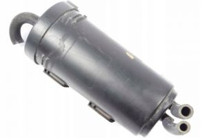
The task of the activated charcoal canister is ventilation and deventilation of the fuel tank and storing the fuel vapors temporarily for subsequent purging.
The hausing of the activated charcoal canister is filled with activated charcoal granulate, divided into different chambers by intermediate walls in order to achieve optimal flow through the activated charcoal. USA with ORVR: Quantities of around 2.7 to 3.5 l.
The fuel vapors released from the fuel tank (USA with ORVR or when refueling) are bonded to the activated charcoal. When purging is activated, they are drawn in by the engine and combusted. The activated charcoal is completely regenerated in the ideal case. The ventilation and deventilation of the fuel tank takes place over the activated charcoal canister.
The activated charcoal canister is located at the rear in the rear left wheelhouse.
|
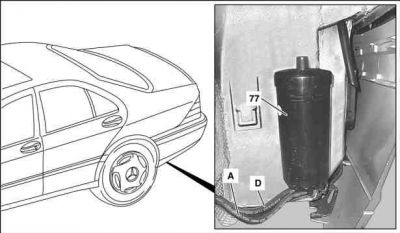
|
|
USA with ORVR:
|
|
Activated charcoal canister shutoff valve (version USA)
|
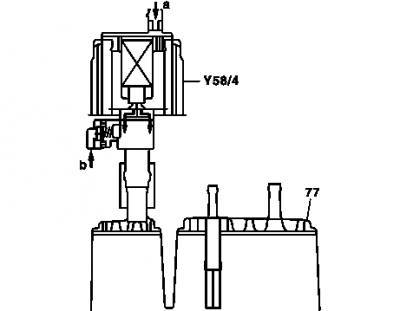
Shown in the design of model 210:
|
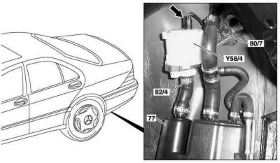
The task of the activated charcoal canister shutoff valve is to close the ventilation of the activated charcoal canister for a leakage test of the fuel system.
The shutoff valve contains a solenoid which closes the valve when energizing. Additionally a mechanical safety valve is installed.
The shutoff valve is located on the top at the vent connection of the activated charcoal canister.
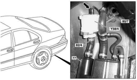
Remove/install shutoff valve
|
Shown on model 220:
|
- Remove rear left wheelhousing liner
- Detach connector (Arrow)
- Unscrew plastic nuts (80/7)
- Replace hose clip (82/4)
- Take out shutoff valve (Y58/4)
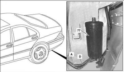
Remove/install activated charcoal canister
|
Shown on MODEL 220
|
- Raise vehicle.
- Remove rear left wheelhousing liner
- Detach activated charcoal canister - purge control valve line (A) and vent valve line - activated charcoal canister to fuel tank (D) at activated charcoal canister (77)
- Remove activated charcoal canister (77). Lift up and out.
- Install in the reverse order
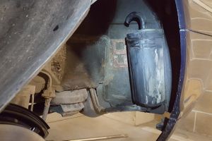 |
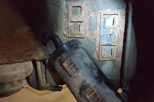 |
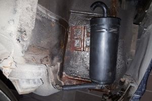 |
Remove/install activated charcoal canister (version USA)
- Lift rear. Remove inner fender from rear fender.
- Detach lines at activated charcoal canister (77)
- Unplug plug socket (arrow) at shutoff valve
- Unscrew plastic nuts (80/7)
- Remove activated charcoal canister (77). Lift up and out.
- Install in the reverse order
Purge control valve
The task of the purge control valve is opening and closing the connecting line between the activated charcoal canister and the intake manifold.
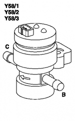
The purge control valve is an electric switchover valve with two line terminals and one 2-pin plug connection.
|
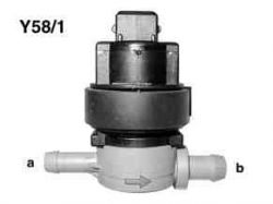
|
 |
The purge control valve (Y58/1) is actuated by the ME control unit by means of a PWM signal (ground side) in line with the operating condition of the engine. If purging is actuated, the passage from the activated charcoal canister (a) to the intake manifold (b) is opened and closed.
The voltage supply to the purge control valve is performed by terminal 87.
The purge valve makes clicking noises in normal operation, they do sometimes seem to get louder as they age.
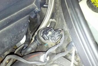
The purge control valve is located in the engine compartment at the left wheelhouse.
|
|
|
Vent valve (non-USA)
|
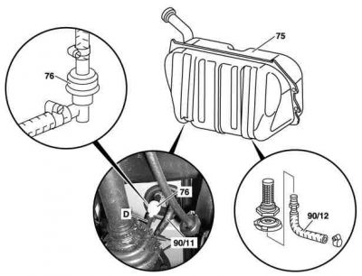
Shows model 220:
|
|
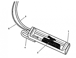
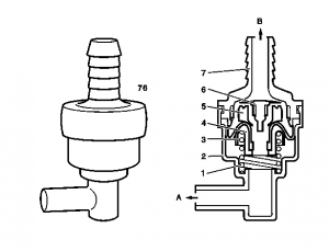
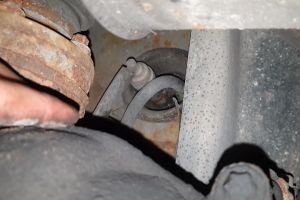
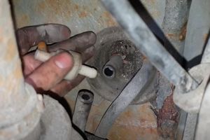
The task of the vent valve is the air admission and ventilation of fuel tank and prevention of overfilling. The vent valve (76) is mounted under the fuel tank in the vent line.
Fuel tank ventilation. The ventilation valve (4) opens at an overpressure of around 30 to 50 mbar. The fuel vapors flow to the activated charcoal canister.
Fuel tank aeration. The air admission valve (6) opens at a vacuum of around 1 to 16 mbar in the fuel tank. Air or fuel vapors are drawn in through the activated charcoal canister.
Refueling. The opening pressure of the vent valve (4) of approx. 30 up to 50 mbar is not achieved if the fuel tank cap is removed. The vent line to the activated charcoal canister remains closed off. This switches off the nozzle more rapidly.
 |
 |
Connection diagram for evaporative emission control system (M113)
(Note: the fuel filter is incorrectly depicted in this picture. For correct depiction refer to M113 USA version picture below.)
Connection diagram of evaporative emission control system (M113 version USA)
Connection diagram for evaporative emission control system (M112)
Parts
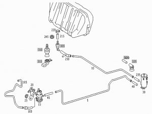
Identifying the components in this diagram with same nomenclature as above:
Issues
Fuel in activated charcoal canister
In normal operation, no fuel should get into activated charcoal canister as it is supposed to store only fuel vapors.
Fuel may get into activated charcoal canister:
- From fuel tank if the fuel tank is overfilled.
- From fuel filter if the fuel pressure regulation membrane in the filter is leaking.
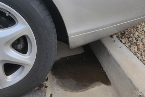
In case fuel gets into the activated charcoal canister, the canister and as well as the fuel filter should be replaced, because the fuel from the canister might have gotten into the membrane vent valve of the fuel filter and damaged it (or shortened its life).
If fuel is in the activated charcoal canister:
- The engine may run rough and stall, because when the ECU purges the fuel "fumes" into engine, it actually gets raw fuel into intake and that causes the engine to sputter.
- The charcoal canister is the only method the fuel tank has of breathing in to fill the void left as the fuel is pumped out. Should it become saturated, the tank will be unable to breath in, the pump will struggle, the car may stall, and the pump may experience premature failure. In some cases the fuel tank can even deform due to the excessive vacuum buildup.
 |
 |
 |
Replacing activated charcoal
When fuel gets into an activated charcoal, the charcoal will become saturated and will be able to adsorb only very little amount of fuel vapors. To some extent the charcoal can be regenerated by burning off the fuel, but it is best to replace charcoal with new activated charcoal.
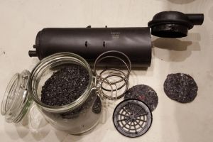
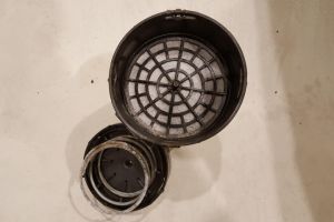
The original W220 activated charcoal canister is filled up with 1 liter of cylindrically-shaped activated charcoal pallets that are 2mm in diameter. The canister is fully serviceable - it is possible to dismantle it, wash the filters and replace the charcoal.
In general, any type of activated charcoal will likely do the job, however, there are a few nuances. Activated charcoal (carbon) is available in different shapes and sizes with different adsorption characteristics. The size affects both the surface area and loss of flow through the carbon. Fish tank carbon should work as well, just that it is optimized for liquid filtering and not filtering of gas vapors. Almost all water filtration carbon is made from bituminous coal, while almost all gas adsorption charcoal is made from coco carbon or wood based carbon.
The simplest way to get new activated charcoal suitable for gas is to buy some cheap activated charcoal canister and remove charcoal from it. The cheapest canister we found is Topran 111022 canister (12 EUR) made for Volkswagen (original part number 1H0201801C). The canister contains approximately 0.75 liters of charcoal of granular shape. If needed, the longer spring from Topran 111022 canister can be used for W220 canister to ensure that the new charcoal (which is slightly less in volume) does not move around inside the canister.
 |
 |
 |
 |
Leak testing
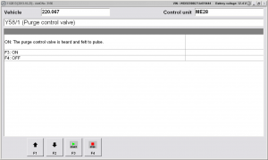
The "Actuations" menu under DAS can be used to manually activate the purge control valve (Y58/1).
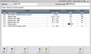
The "Actual values" menu under DAS can be used to observe whether and to what extent (in percents) the purge control valve is actuated when the engine is running.
 |
 |
