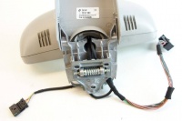
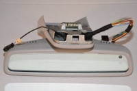
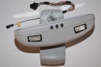
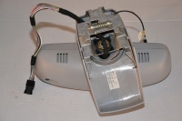
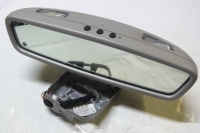
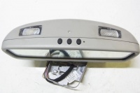
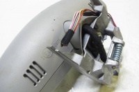
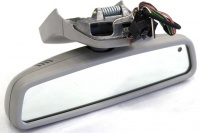
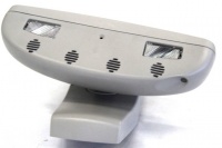
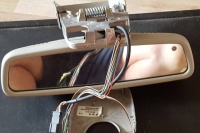
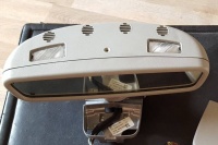
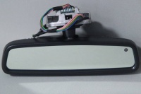
Rearview mirror: Difference between revisions
(→Part numbers: photos) |
(→Ambient/vanity lamp: wires) |
||
| (38 intermediate revisions by the same user not shown) | |||
| Line 11: | Line 11: | ||
== Part numbers == | == Part numbers == | ||
[[File:B69018000020.041110.png|thumb|none|Mirror-related parts in [[EPC]].]] | |||
There are several versions of W220 rearview mirrors. Left-hand drive vehicles and right-hand drive vehicles have different rearview mirrors. | There are several versions of W220 rearview mirrors. Left-hand drive vehicles and right-hand drive vehicles have different rearview mirrors. | ||
Similarly, there are different versions of rearview mirrors depending on the option codes vehicle is equipped with - | Similarly, there are different versions of rearview mirrors depending on the option codes vehicle is equipped with - | ||
| Line 42: | Line 44: | ||
|A2208102617 | |A2208102617 | ||
|From Date: 31/10/2002, To Date: 30/09/2003, option 804, From Date: 30/09/2003 not valid for option 383/386/388 | |From Date: 31/10/2002, To Date: 30/09/2003, option 804, From Date: 30/09/2003 not valid for option 383/386/388 | ||
| | |||
| | |||
| | |||
|- | |- | ||
|A2208100017 | |A2208100017 | ||
| Line 51: | Line 56: | ||
|A2208102717 | |A2208102717 | ||
|From Date: 30/09/2003, option 349/380/381/382/383/384/385/386/388 | |From Date: 30/09/2003, option 349/380/381/382/383/384/385/386/388 | ||
| | |||
| | |||
| | |||
|- | |- | ||
|A2208101317 | |A2208101317 | ||
|From Date: 31/10/2002, To Date: 30/09/2003, option 249+804 | |From Date: 31/10/2002, To Date: 30/09/2003, option 249+804 | ||
| | |||
| | |||
| | |||
|- | |- | ||
|A2208104017 | |A2208104017 | ||
|From Date: 30/09/2003, option 249 | |From Date: 30/09/2003, option 249 | ||
| | |||
| | |||
| | |||
|- | |- | ||
|A2208101717 | |A2208101717 | ||
| Line 84: | Line 98: | ||
|A2208101517 | |A2208101517 | ||
|From Date: 31/10/2002, To Date: 30/09/2003, option 231+249+804 | |From Date: 31/10/2002, To Date: 30/09/2003, option 231+249+804 | ||
| | |||
| | |||
| | |||
|- | |- | ||
|A2208103817 | |A2208103817 | ||
|From Date: 30/09/2003, option 231+249 | |From Date: 30/09/2003, option 231+249 | ||
| | |||
| | |||
| | |||
|- | |- | ||
|A2208102017 | |A2208102017 | ||
| Line 92: | Line 112: | ||
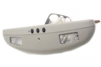
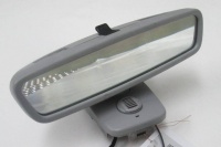
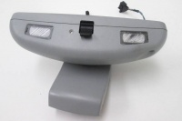
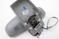
|[[File:W220_A2208102017_front.jpg|200px]] | |[[File:W220_A2208102017_front.jpg|200px]] | ||
|[[File:W220_A2208102017_bottom.jpg|200px]] | |[[File:W220_A2208102017_bottom.jpg|200px]] | ||
| | |||
|- | |||
|A2208103517 | |||
|''(not in EPC, but seems to be the successor of A2208102017)'' | |||
|[[File:W220_A2208103517_front.jpg|200px]] | |||
|[[File:W220_A2208103517_bottom.jpg|200px]] | |||
| | | | ||
|- | |- | ||
|A2208102217 | |A2208102217 | ||
|To Date: 30/09/2003, option 231+249+[349/380/381/382/383/385]+804 | |To Date: 30/09/2003, option 231+249+[349/380/381/382/383/385]+804 | ||
| | |||
| | |||
| | |||
|- | |- | ||
|A2208103317 | |A2208103317 | ||
| Line 167: | Line 196: | ||
* The left reading lamp (A67e1) and right reading lamp (A67e2) as well as the ambient light (A67e3) are also integrated in the mirror housing. | * The left reading lamp (A67e1) and right reading lamp (A67e2) as well as the ambient light (A67e3) are also integrated in the mirror housing. | ||
==Ambient lamp== | ==Wiring diagram== | ||
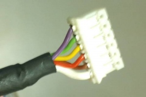
Rearview mirror is connected to the overhead control panel control module (N70). | |||
[[File:W220_rearview_mirror_connector_A0005459103.jpg|thumb|none|Rearview mirror connector (A0005459103).]] | |||
==Ambient/vanity lamp== | |||
<!-- GF82.20-P-2021S, Switching on/off ambient lamp, function --> | <!-- GF82.20-P-2021S, Switching on/off ambient lamp, function --> | ||
The ambient lamp (A67e3) is a bright LED located in the interior | The ambient lamp (A67e3) is a bright LED (powered by 12 volts) located in the interior | ||
rear view mirror (A67). It serves for illumination of the center console. | rear view mirror (A67). It serves for illumination of the center console. | ||
The ambient lamp is switched on automatically when C.15r switched on | The ambient lamp is switched on automatically when C.15r is switched on | ||
and switched off automatically when C.15r is switched off. | and switched off automatically when C.15r is switched off (i.e., the ambient lamp is on when the ignition is on). | ||
The ambient lamp (A67e3) is controlled directly by the overhead | The ambient lamp (A67e3) is controlled directly by the overhead | ||
| Line 184: | Line 219: | ||
switch daylight sensor (B32/1) and the position of the door | switch daylight sensor (B32/1) and the position of the door | ||
contact ON and OFF switch (N70s3). | contact ON and OFF switch (N70s3). | ||
{| | |||
|[[File:W220_rearview_mirror_ambient_lamp_LED.jpg|thumb|none|Ambient lamp]] | |||
|[[File:W220_rearview_mirror_vanity_light_on.jpg|thumb|none|Ambient lamp on]] | |||
|[[File:W220_rearview_mirror_vanity_lamp_wires.jpg|thumb|none|Ambient lamp wires]] | |||
|} | |||
Note: in case ambient light LED is borne out, the error code is not registered. | |||
==Reading lamps== | ==Reading lamps== | ||
The left reading lamp (A67e1) and right reading lamp (A67e2) are integrated in the mirror housing. | The left reading lamp (A67e1) and right reading lamp (A67e2) are integrated in the mirror housing. | ||
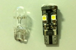
The bulb used is 12V/6W (A0025443894). | |||
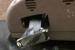
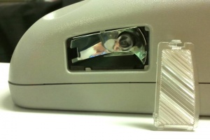
For some rearview mirrors the reading lamp cover is attached to the lamp housing, while for others the cover is attached to mirror housing (see below). | |||
{| | |||
|[[File:W220_rearview_mirror_reading_lamp_cover_type2.jpg|thumb|none|Reading lamp with lamp cover removed (type A).]] | |||
|[[File:W220_rearview_mirror_reading_lamp_opened.jpg|thumb|none|Reading lamp with lamp cover removed (type B).]] | |||
|[[File:W220_rearview_mirror_reading_lamp_original_LED.jpg|thumb|none|Original 6W T10 Wedge bulb and LED upgrade.]] | |||
|} | |||
{| class="wikitable" | |||
! Error Code | |||
! Description | |||
|- | |||
|B1022 | |||
|Component A67e2 (Right reading lamp) has Short circuit or Idle speed. | |||
|- | |||
|B1023 | |||
|Component A67e1 (Left reading lamp) has Short circuit or Idle speed. | |||
|} | |||
== Automatic dimming function == | == Automatic dimming function == | ||
| Line 203: | Line 266: | ||
in the mirror housing (rear side) and the automatic dimming interior | in the mirror housing (rear side) and the automatic dimming interior | ||
rearview mirror sensor (A67h1) in the mirror glass of the interior rearview mirror unit (A67). | rearview mirror sensor (A67h1) in the mirror glass of the interior rearview mirror unit (A67). | ||
{| | |||
|[[File:W220_rearview_mirror_dimming_forward_sensor.jpg|thumb|none|Ambient light forward sensor (A67h1).]] | |||
|[[File:W220_rearview_mirror_dimming_backward_sensor.jpg|thumb|none|Ambient light backward sensor (A67h2).]] | |||
|} | |||
If an interior light is switched on or the reverse gear (CAN message) is engaged, | If an interior light is switched on or the reverse gear (CAN message) is engaged, | ||
| Line 208: | Line 276: | ||
This is accomplished by an additional signal lead from the overhead control panel control module | This is accomplished by an additional signal lead from the overhead control panel control module | ||
(N70) to the interior rearview mirror unit (A67). | (N70) to the interior rearview mirror unit (A67). | ||
Function prerequisites: | Function prerequisites: | ||
* Voltage not too low or too high | * Voltage not too low or too high | ||
* C. 15R or | * C.15R or C.15 ON | ||
The interior rearview mirror unit (A67) serves also as master for the automatic dimming [[Exterior mirrors|exterior rearview mirror]] (driver's side). | |||
== Memory feature == | == Memory feature == | ||
| Line 271: | Line 294: | ||
<!-- SI68.40-P-0001A, 17.06.2004, Service Information: Discontinuation of memory feature in inside rearview mirror. --> | <!-- SI68.40-P-0001A, 17.06.2004, Service Information: Discontinuation of memory feature in inside rearview mirror. --> | ||
'''Note:''' As of chassis 392659 | '''Note:''' As of chassis 392659 (10/2003) the inside rearview mirror memory function is no longer part of the memory package | ||
the inside rearview mirror memory function is no longer part of the memory package | |||
(seat adjustment, steering wheel height adjustment and outside mirror adjustment). | (seat adjustment, steering wheel height adjustment and outside mirror adjustment). | ||
The memory feature for the electrical inside rearview mirror can no longer be ordered | The memory feature for the electrical inside rearview mirror can no longer be ordered | ||
and is no longer installed in the series production of the models specified above. | and is no longer installed in the series production of the models specified above. | ||
<!--The current price list can be used to support this statement.--> | <!--The current price list can be used to support this statement.--> | ||
This is the reason why vehicles produced after 10/2003 may have this error code present: | |||
{| class="wikitable" | |||
! Error Code | |||
! Description | |||
|- | |||
|B10B4 | |||
|Component A67r1 (Vertical position potentiometer) has Open circuit or Short circuit to ground. This fault can be ignored as of manufacture year 10.2003. | |||
|- | |||
|B10B6 | |||
|Component A67r2 (Horizontal position potentiometer) has Open circuit or Short circuit to ground. This fault can be ignored as of manufacture year 10.2003. | |||
|} | |||
==Hands-free system microphone group== | ==Hands-free system microphone group== | ||
<!-- GF68.49-P-2100-02S Inside rearview mirror, design --> | <!-- GF68.49-P-2100-02S Inside rearview mirror, design --> | ||
<!--Additional equipment on vehicles as of 1.9.03 with telephone or with telephone and voice control system (VCS)--> | <!--Additional equipment on vehicles as of 1.9.03 with telephone or with telephone and voice control system (VCS)--> | ||
[[File:W220_Hands-free_system_microphone_group.jpg|thumb|none|A67b1 - Hands-free system microphone group]] | {| | ||
|[[File:W220_Hands-free_system_microphone_group.jpg|thumb|none|A67b1 - Hands-free system microphone group]] | |||
|} | |||
<!-- GF68.49-P-2100-03S Inside rearview mirror, function --> | <!-- GF68.49-P-2100-03S Inside rearview mirror, function --> | ||
On vehicles as of 01/09/2003 with telephone or with telephone and voice control system (VCS) | On vehicles as of 01/09/2003 with telephone or with telephone and voice control system (VCS), | ||
a hands-free system microphone group (A67b1) is integrated in the inside rearview mirror (A67). | a hands-free system microphone group (A67b1) is integrated in the inside rearview mirror (A67). | ||
The following functions can be performed via the hands-free system microphone group (A67b1): | The following functions can be performed via the hands-free system microphone group (A67b1): | ||
| Line 291: | Line 328: | ||
The signals are transmitted to the hands-free system control module (A35/1) or the voice control module (A35/11) via the hands-free system microphone group (A67b1). | The signals are transmitted to the hands-free system control module (A35/1) or the voice control module (A35/11) via the hands-free system microphone group (A67b1). | ||
{| | |||
|[[File:A2118200435_in_cover.jpg|thumb|none|Microphone group (A67b1) in the mirror casing.]] | |||
|[[File:A2118200435_top.jpg|thumb|none|A2118200435 microphone group module (top).]] | |||
|[[File:A2118200435_bottom.jpg|thumb|none|A2118200435 microphone group module (bottom).]] | |||
|} | |||
{| | |||
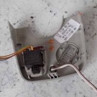
|[[File:A2118200435_inside_a.jpg|thumb|none|A2118200435 microphone group module (dissected).]] | |||
|[[File:A2118200435_inside_b.jpg|thumb|none|A2118200435 microphone group module (dissected).]] | |||
|[[File:W220_rearview_mirror_cover_size_microphone_group.jpg|thumb|none|Usual mirror casing (top) and casing with microphone group embedded (bottom).]] | |||
|} | |||
{| | |||
|[[File:A0015403281_housing_connector.jpg|thumb|none|A0015403281 connector connecting to the voice control module extension wire.]] | |||
|[[File:6pin_connector_to_A2118200435.jpg|thumb|none|6-PIN connector connecting to the microphone group module A2118200435.]] | |||
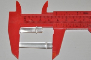
|[[File:W220_rearview_mirror_sensor_lens.jpg|thumb|none|Usual sensor lens (25.5mm) and sensor lens for casing with microphone group embedded (38mm).]] | |||
|} | |||
The casing for rearview mirror with embedded microphone group is bigger in volume than the usual mirror casing (see the picture above). The microphone group module has a separate 6-wire cable that connects to voice control module extension wire that is centered under the headliner. | |||
==Garage door opener== | ==Garage door opener== | ||
| Line 315: | Line 370: | ||
===Program remote control=== | ===Program remote control=== | ||
{| | |||
|{{#ev:youtube|https://www.youtube.com/watch?v=oD61zlFu9qU|320|left|How to Program Garage Door Opener.|frame}} | |||
| | |||
Function requirements: | Function requirements: | ||
* Circuit 15R or circuit 15 ON | * Circuit 15R or circuit 15 ON | ||
| Line 321: | Line 380: | ||
* Continue to hold button 1 garage door opener (A67s1), button 2 garage door opener (A67s2) or button 3 garage door opener (A67s3)and hold garage door opener remote control with transmit button pressed for t < 90 s. After successful programming the garage door opener indicator lamp (A67e4) flashes rapidly (f = 5.5 Hz) for a duration of approx. 10 s. | * Continue to hold button 1 garage door opener (A67s1), button 2 garage door opener (A67s2) or button 3 garage door opener (A67s3)and hold garage door opener remote control with transmit button pressed for t < 90 s. After successful programming the garage door opener indicator lamp (A67e4) flashes rapidly (f = 5.5 Hz) for a duration of approx. 10 s. | ||
* Release the two transmit buttons and program additional transmitters as required. | * Release the two transmit buttons and program additional transmitters as required. | ||
|} | |||
In order to save the vehicle battery, the transmitter switches off | In order to save the vehicle battery, the transmitter switches off | ||
automatically in the learn-in mode, if programming is not accomplished after approx. 100 seconds. | automatically in the learn-in mode, if programming is not accomplished after approx. 100 seconds. | ||
| Line 348: | Line 407: | ||
==Removing inside rearview mirror== | ==Removing inside rearview mirror== | ||
Rearview mirror is attached to the sealing using a spring mechanism. Hence the mirror can be detached and reattached simply by force. | |||
Mirror retaining plate (A2208100111) is attached to roof frame using three screws (N007981003279). | |||
{| | |||
|[[File:W220_rearview_mirror_spring.jpg|thumb|none|Rearview mirror retaining spring.]] | |||
|[[File:W220_rearview_mirror_inside_plate_A2208100111.jpg|thumb|none|Mirror retaining plate A2208100111.]] | |||
|} | |||
<!-- AR68.40-P-0001M, Removing and installing inside rearview mirror --> | <!-- AR68.40-P-0001M, Removing and installing inside rearview mirror --> | ||
{| | {| | ||
| Line 364: | Line 432: | ||
# Remove inside rearview mirror (1) by inserting screwdriver between inside rearview mirror (1) and retaining plate (4) and prying out inside rearview mirror | # Remove inside rearview mirror (1) by inserting screwdriver between inside rearview mirror (1) and retaining plate (4) and prying out inside rearview mirror | ||
# Install in opposite order | # Install in opposite order | ||
==Rain sensor cover== | |||
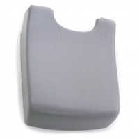
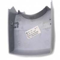
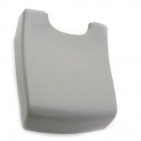
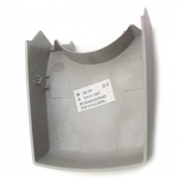
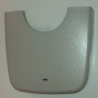
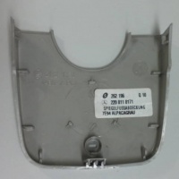
Rain sensor cover Part no. A2208110007 is universal for all types of rear view mirrors. The only difference is in color. | |||
[[Facelift]] models use different tone of gray - alpaca gray. | |||
{| | |||
|[[File:W220_A2208110007_front_origongray.jpg|thumb|200px|none|Rain sensor cover in origon gray (pre-facelift) front.]] | |||
|[[File:W220_A2208110007_back_origongray.jpg|thumb|200px|none|Rain sensor cover in origon gray (pre-facelift) back.]] | |||
|[[File:W220_A2208110007_front_alpacagray.jpg|thumb|200px|none|Rain sensor cover in alpaca gray (facelift) front.]] | |||
|[[File:W220_A2208110007_back_alpacagray.jpg|thumb|200px|none|Rain sensor cover in alpaca gray (facelift) back.]] | |||
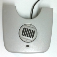
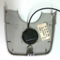
|} | |||
==Mirror cover== | |||
{| class="wikitable" | |||
! Part No. | |||
! Notes | |||
! Front | |||
! Back | |||
|- | |||
|A2208110171 | |||
| | |||
|[[File:W220_A2208110171_front.jpg|200px]] | |||
|[[File:W220_A2208110171_back.jpg|200px]] | |||
|- | |||
|A2208100764 | |||
|option 278/316/317/329/852/853/854 | |||
|[[File:W220_A2208100764_front.jpg|200px]] | |||
|[[File:W220_A2208100764_back.jpg|200px]] | |||
|- | |||
|A2208100464 | |||
|Left-hand drive, option 347/349/855/930 | |||
|[[File:W220_A2208100464_front.jpg|200px]] | |||
|[[File:W220_A2208100464_back.jpg|200px]] | |||
|- | |||
|A2208101564 | |||
|Left-hand drive, option 349+804,383+804,384+804,359,383,384 | |||
|[[File:W220_A2208101564_front.jpg|200px]] | |||
|[[File:W220_A2208101564_back.jpg|200px]] | |||
|- | |||
|A2208100564 | |||
|Right-hand drive, option 349/855 | |||
| | |||
| | |||
|- | |||
|A2208101664 | |||
|Right-hand drive, option 349+804,383+804,383,349 | |||
| | |||
| | |||
|} | |||
{| | |||
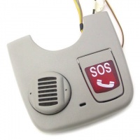
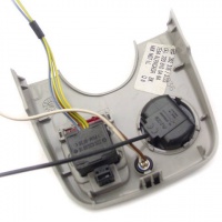
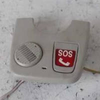
|[[File:W220_A2208200010_distress_call_switch.jpg|thumb|none|Distress call switch (A2208200010).]] | |||
|[[File:W220_microphone_A2208201735.jpg|thumb|none|Microphone for hands-free system (A2208201735).]] | |||
|} | |||
==Disassembling A2208100017== | |||
Parts of rearview mirror A2208100017 (dimming function + memory function). | |||
{| | |||
|[[File:A2208100017_inside_front_cover.jpg|thumb|none|]] | |||
|[[File:A2208100017_inside_cover.jpg|thumb|none|]] | |||
|[[File:A2208100017_inside_part.jpg|thumb|none|]] | |||
|} | |||
{| | |||
|[[File:A2208100017_inside_board.jpg|thumb|none|]] | |||
|[[File:A2208100017_inside_board_zoom.jpg|thumb|none|]] | |||
|[[File:A2208100017_inside_board_mirror.jpg|thumb|none|]] | |||
|} | |||
{| | |||
|[[File:A2208100017_adjustment_mechanism.jpg|thumb|none|]] | |||
|[[File:A2208100017_inside_mirror.jpg|thumb|none|]] | |||
|} | |||
==Disassembling A2208103517== | |||
Parts of rearview mirror A2208103517 (dimming function + microphone group). | |||
{| | |||
|[[File:A2208103517_inside_front_cover.jpg|thumb|none|]] | |||
|[[File:A2208103517_inside_cover.jpg|thumb|none|]] | |||
|[[File:A2208103517_inside_part.jpg|thumb|none|]] | |||
|} | |||
{| | |||
|[[File:A2208103517_inside_board.jpg|thumb|none|]] | |||
|[[File:A2208103517_inside_mirror.jpg|thumb|none|]] | |||
|[[File:A2208103517_inside_board_plate.jpg|thumb|none|]] | |||
|} | |||
{| | |||
|[[File:A2208103517_inside_board_front.jpg|thumb|none|]] | |||
|[[File:A2208103517_inside_board_back.jpg|thumb|none|]] | |||
|[[File:A2208103517_adjustment_mechanism.jpg|thumb|none|]] | |||
|} | |||
{| | |||
|[[File:A2208103517_adjustment_mechanism_back.jpg|thumb|none|]] | |||
|} | |||
== Rearview mirror with memory function and microphone group == | |||
There are no rearview mirrors that have both, the memory function and microphone group embedded (the reason could be that memory function was discontinued at 10/2003, before the microphone group in mirror was introduced). However, it is possible to construct one from two mirrors by joining mirror cover that has microphone group embedded to mirror that has memory function. The only challenge is to pull the microphone group wire through the mirror holder. To do that, the wire connector has to be detached from the wire (see below). | |||
{| | |||
|[[File:W220_6pin_connector_disassembled.jpg|thumb|none|Microphone group wire with connector detached.]] | |||
|[[File:A2208100017_microphone_group_wire.jpg|thumb|none|Microphone group wire pulled through.]] | |||
|[[File:W220_A2208100017_front_with_A2208103517_back.jpg|thumb|none|A2208100017 front with A2208103517 back.]] | |||
|} | |||
{| | |||
|[[File:W220_rearview_mirror_memory_and_microphone_group.jpg|thumb|none|Rearview mirror with mirror and microphone group.]] | |||
|} | |||
Latest revision as of 11:00, 10 August 2021
Location
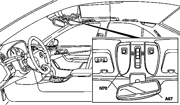
The interior rearview mirror unit (A67) is located on the overhead control panel control module (N70) centered at front of the headliner.
|
|
Part numbers
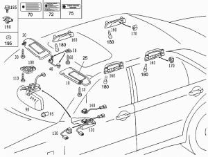
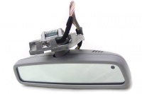
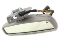
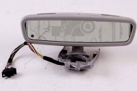
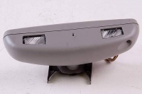
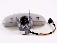
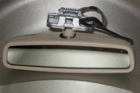
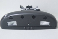
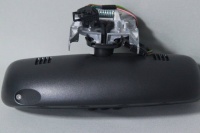
There are several versions of W220 rearview mirrors. Left-hand drive vehicles and right-hand drive vehicles have different rearview mirrors. Similarly, there are different versions of rearview mirrors depending on the option codes vehicle is equipped with - garage door opener (option code 231/232), dimming function (option code 249), memory function (option code 275) and telephone or voice control system (option codes 349/359/380/381/382/383/384/385/386/388).
Left-hand drive vehicles
Right-hand drive vehicles (UK)
| Part No. | Notes |
|---|---|
| A2208100117 | option 275 |
| A2208101417 | From Date: 31/10/2002, To Date: 30/09/2003, option 249+804 |
| A2208103917 | From Date: 30/09/2003, option 249 |
| A2208100417 | To Date: 30/09/2003, Replaced by: A2208101917, option 231+275 |
| A2208101917 | To Date: 30/09/2003, Replaced by: A2208101917, option 231+275 |
| A2208101617 | From Date: 31/10/2002, To Date: 30/09/2003, option 231+249+804 |
| A2208103717 | From Date: 30/09/2003, option 231+249 |
| A2208102117 | From Date: 31/10/2002, To Date: 30/09/2003, option 249+[349/380/381/382/383]+804 |
| A2208103417 | From Date: 30/09/2003, option 249+[380/381/382/383/386/388] |
| A2208102317 | To Date: 30/09/2003, option 231+249+[349/380/381/382/383]+804 |
| A2208103217 | From Date: 30/09/2003, option 231+249+[380/381/382/383/386/388] |
Design
Tasks:
- The inside rearview mirror (A67) can be adjusted manually.
- Depending on the equipment (see below), the manually adjusted mirror position can be stored, called up later with the memory function and actuated automatically.
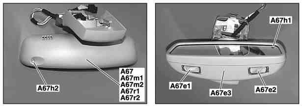
- The mirror lens of the inside rearview mirror (A67) can be electro-chromatically dimmed. Dimming is accomplished according to the variables measured by the mirror dimming forward sensor (A67h1) and mirror dimming backward sensor (A67h2).
- The left reading lamp (A67e1) and right reading lamp (A67e2) as well as the ambient light (A67e3) are also integrated in the mirror housing.
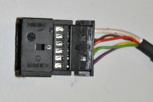
Wiring diagram
Rearview mirror is connected to the overhead control panel control module (N70).
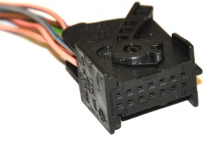
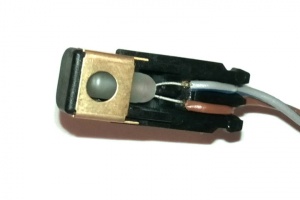
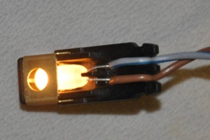
Ambient/vanity lamp
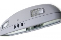
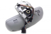
The ambient lamp (A67e3) is a bright LED (powered by 12 volts) located in the interior rear view mirror (A67). It serves for illumination of the center console.
The ambient lamp is switched on automatically when C.15r is switched on and switched off automatically when C.15r is switched off (i.e., the ambient lamp is on when the ignition is on).
The ambient lamp (A67e3) is controlled directly by the overhead control panel control module (N70). The overhead control panel control module (N70) receives the information "Status c.15r" for this purpose via the CAN bus from the electronic ignition/starter switch control module (N73).
The ambient lamp is independent of the automatic light switch daylight sensor (B32/1) and the position of the door contact ON and OFF switch (N70s3).
 |
 |
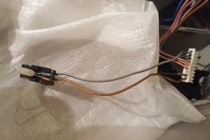 |
Note: in case ambient light LED is borne out, the error code is not registered.
Reading lamps
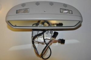
The left reading lamp (A67e1) and right reading lamp (A67e2) are integrated in the mirror housing. The bulb used is 12V/6W (A0025443894).
For some rearview mirrors the reading lamp cover is attached to the lamp housing, while for others the cover is attached to mirror housing (see below).
 |
 |
 |
| Error Code | Description |
|---|---|
| B1022 | Component A67e2 (Right reading lamp) has Short circuit or Idle speed. |
| B1023 | Component A67e1 (Left reading lamp) has Short circuit or Idle speed. |
Automatic dimming function
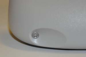
For vehicles with option code 249 - INSIDE AND OUTSIDE MIRROR AUTOMATIC DIMMING the interior rearview mirror unit (A67) can be dimmed electro-chromatically. For this purpose, a layer of electrolyte gel is located in the mirror glass between the reflector and the cover lens. Voltage connected to the gel modifies its permeability to light. The light reaching the surface of the mirror is reflected to a greater or lesser extent due to the magnitude of the actuating voltage. The actuating voltage is controlled by the electronic circuitry in the interior rearview mirror. This procedure is subject to the ambient light and the light reaching the mirror.
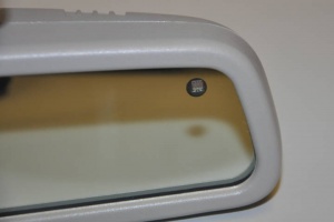
These two input variables are sensed by the ambient light sensor (A67h2) in the mirror housing (rear side) and the automatic dimming interior rearview mirror sensor (A67h1) in the mirror glass of the interior rearview mirror unit (A67).
 |
 |
If an interior light is switched on or the reverse gear (CAN message) is engaged, the interior rearview mirror is always switched to a brighter setting. This is accomplished by an additional signal lead from the overhead control panel control module (N70) to the interior rearview mirror unit (A67).
Function prerequisites:
- Voltage not too low or too high
- C.15R or C.15 ON
The interior rearview mirror unit (A67) serves also as master for the automatic dimming exterior rearview mirror (driver's side).
Memory feature
For vehicles with option code 275 - MEMORY PACKAGE (DRIVER SEAT, STRG. COL., MIRROR) the inside rearview mirror (A67) can be adjusted automatically with the memory function, i.e. stored mirror position can be called up. For this purpose, two DC motors, a vertical adjustment motor (A67m1) and a horizontal adjustment motor (A67m2) are present in the housing actuated by the overhead control panel control module (N70). The vertical position potentiometer (A67r1) and horizontal position potentiometer (A67r2) are located next to the motors for position recognition.
Note: As of chassis 392659 (10/2003) the inside rearview mirror memory function is no longer part of the memory package (seat adjustment, steering wheel height adjustment and outside mirror adjustment). The memory feature for the electrical inside rearview mirror can no longer be ordered and is no longer installed in the series production of the models specified above.
This is the reason why vehicles produced after 10/2003 may have this error code present:
| Error Code | Description |
|---|---|
| B10B4 | Component A67r1 (Vertical position potentiometer) has Open circuit or Short circuit to ground. This fault can be ignored as of manufacture year 10.2003. |
| B10B6 | Component A67r2 (Horizontal position potentiometer) has Open circuit or Short circuit to ground. This fault can be ignored as of manufacture year 10.2003. |
Hands-free system microphone group
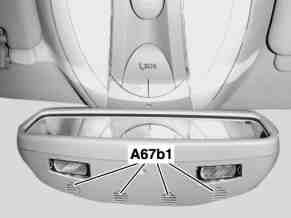 |
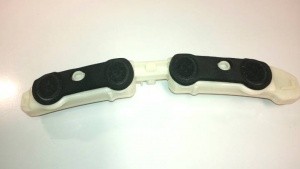
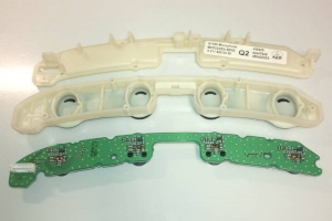
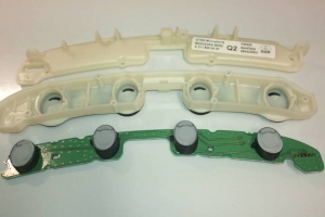
On vehicles as of 01/09/2003 with telephone or with telephone and voice control system (VCS), a hands-free system microphone group (A67b1) is integrated in the inside rearview mirror (A67). The following functions can be performed via the hands-free system microphone group (A67b1):
- Voice input for making telephone calls using the hands-free system
- Voice input for voice control system (VCS) (interactive dialog with VCS)
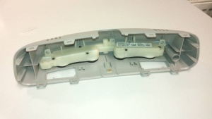
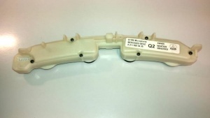
The signals are transmitted to the hands-free system control module (A35/1) or the voice control module (A35/11) via the hands-free system microphone group (A67b1).
 |
 |
 |
 |
 |
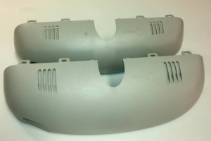 |
The casing for rearview mirror with embedded microphone group is bigger in volume than the usual mirror casing (see the picture above). The microphone group module has a separate 6-wire cable that connects to voice control module extension wire that is centered under the headliner.
Garage door opener
Vehicles with option code 231 - GARAGE DOOR OPENER or 232 - GARAGE DOOR OPENER WITH 284 - 390 MHZ FREQUENCY have garage door opener buttons integrated in the rearview mirror.
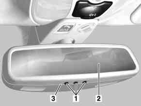
|
|
Garage door opener, function
The garage door opener consists of an adaptive radio remote control with three transmit buttons. With these three buttons: Button 1 garage door opener (A67s1), button 2 garage door opener (A67s2) or button 3 garage door opener (A67s3) it is possible to activate various receivers for the opening and closing system of the doors and gates.
Program remote control
|
Function requirements:
|
In order to save the vehicle battery, the transmitter switches off automatically in the learn-in mode, if programming is not accomplished after approx. 100 seconds.
Transmitter mode
If button 1 garage door opener (A67s1), button 2 garage door opener (A67s2) or button 3 garage door opener (A67s3) is actuated, the signal learned in for this memory space is transmitted activating the associated garage door drive.
The garage door opener signal has a range of at least 15 m.
The transmitter buttons (1) as well as the transmitter for opening the garage door are integrated into the inside rearview mirror (2).
Erasing
- C. 15 R or c. 15 ON.
- Press button 1 of garage door opener (A67s1) and button 3 of garage door opener (A67s3) simultaneously for approx. 20 s. The garage door opener indicator lamp (A67e4) starts flashing.
- Release button 1 on garage door opener (A67s1) and button 3 on garage door opener (A67s3) when garage door opener indicator lamp (A67e4) is flashing within 10 s after it starts flashing. The existing data of the memory locations is erased.
The memories are erased by actuating the button 1 garage door opener (A67s1) and button 3 garage door opener (A67s3) for longer than 20 ms. Successful erasure of all memory locations is indicated for approx. 10 s by the LED flashing rapidly.
Removing inside rearview mirror
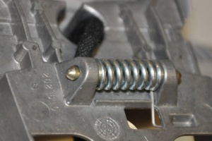
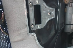
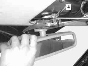
Rearview mirror is attached to the sealing using a spring mechanism. Hence the mirror can be detached and reattached simply by force. Mirror retaining plate (A2208100111) is attached to roof frame using three screws (N007981003279).
 |
 |
|
|
|
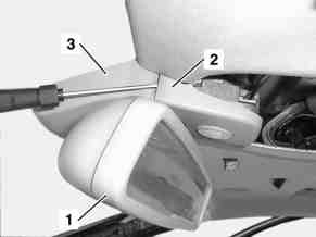
- Remove overhead control panel control module with front dome lamp
- Unclip paneling (2) on inside rearview mirror
- Remove paneling (3)
- Remove inside rearview mirror (1) by inserting screwdriver between inside rearview mirror (1) and retaining plate (4) and prying out inside rearview mirror
- Install in opposite order
Rain sensor cover
Rain sensor cover Part no. A2208110007 is universal for all types of rear view mirrors. The only difference is in color. Facelift models use different tone of gray - alpaca gray.
Mirror cover
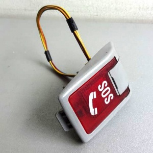 |
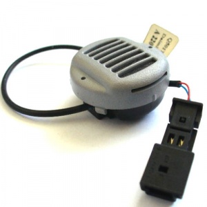 |
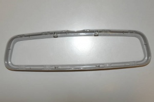
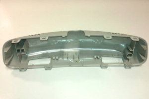
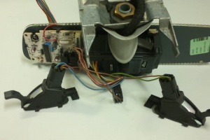
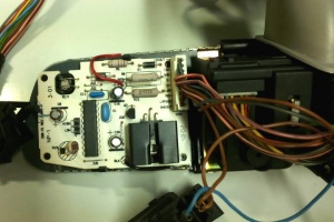
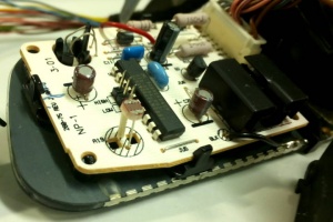
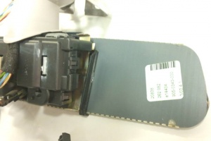
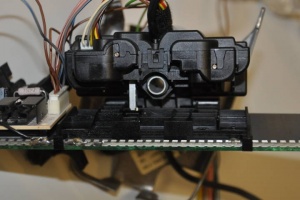
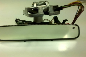
Disassembling A2208100017
Parts of rearview mirror A2208100017 (dimming function + memory function).
 |
 |
 |
 |
 |
 |
 |
 |
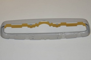
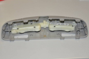
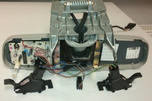
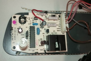
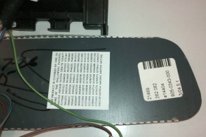
Disassembling A2208103517
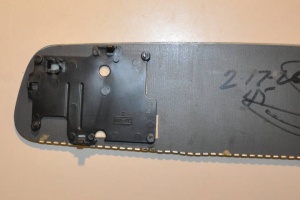
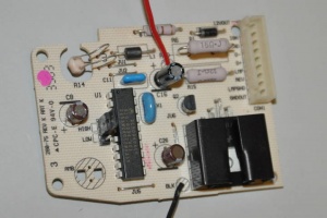
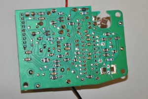
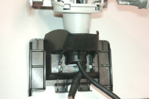
Parts of rearview mirror A2208103517 (dimming function + microphone group).
 |
 |
 |
 |
 |
 |
 |
 |
 |
 |
Rearview mirror with memory function and microphone group
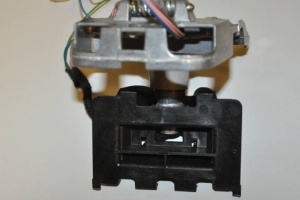
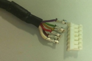
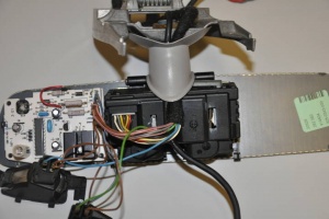
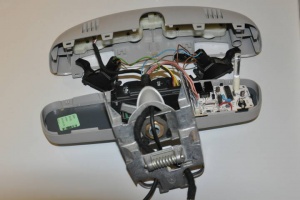
There are no rearview mirrors that have both, the memory function and microphone group embedded (the reason could be that memory function was discontinued at 10/2003, before the microphone group in mirror was introduced). However, it is possible to construct one from two mirrors by joining mirror cover that has microphone group embedded to mirror that has memory function. The only challenge is to pull the microphone group wire through the mirror holder. To do that, the wire connector has to be detached from the wire (see below).
 |
 |
 |
 |
