Trunk: Difference between revisions
(→Resources: two more videos added) |
|||
| (23 intermediate revisions by 2 users not shown) | |||
| Line 155: | Line 155: | ||
==Remote Closing== | ==Remote Closing== | ||
On vehicles with option code [[Data_Card#881_-_REMOTE_TRUNK_LOCKING|881 - REMOTE TRUNK LOCKING]] | On vehicles with option code [[Data_Card#881_-_REMOTE_TRUNK_LOCKING|881 - REMOTE TRUNK LOCKING]] | ||
the trunk lid can be closed by a press of button. | the trunk lid can be opened and closed by a press of button. | ||
If the trunk lid comes into contact with an object while closing (e.g. luggage that has been piled too high) in the upper motion sequence, the closing procedure is stopped and the trunk reopens slightly. | If the trunk lid comes into contact with an object while closing (e.g. luggage that has been piled too high) in the upper motion sequence, the closing procedure is stopped and the trunk reopens slightly. | ||
The closing procedure can be stopped at any time by pressing the trunk lid closing switch (on the driver's door), the trunk lid closing switch (1), or the "trunk lid unlock" button on the [[SmartKey]]. | The closing procedure can be stopped at any time by pressing the trunk lid closing switch (on the driver's door), the trunk lid closing switch (1), or the "trunk lid unlock" button on the [[SmartKey]]. | ||
===Closing from the outside === | |||
{| | {| | ||
| Line 188: | Line 182: | ||
The turn signals flash three times to confirm locking. | The turn signals flash three times to confirm locking. | ||
=== Closing from the inside === | |||
The trunk lid can be closed from the inside using the opening switch if the vehicle is stationary. | The trunk lid can be closed from the inside using the opening switch if the vehicle is stationary. | ||
| Line 195: | Line 189: | ||
Press remote trunk lid switch (2) until the indicator lamp (1) goes out and trunk lid is closed. | Press remote trunk lid switch (2) until the indicator lamp (1) goes out and trunk lid is closed. | ||
To interrupt the closing procedure release remote trunk lid switch (2). | To interrupt the closing procedure release remote trunk lid switch (2). | ||
=== Limiting opening height === | |||
The trunk lid opening height can be limited when transporting goods on a roof rack (e.g. presence of an MB sport luggage container). | |||
When activated, the trunk lid opens to approximately the height of the roof edge. | |||
You can activate the limiting opening height of trunk lid using the control system or menu in instrument cluster. | |||
{| | |||
|[[File:W220_opening_limiter_trunk_lid.jpg|thumb|none|Instrument cluster setting for limiting trunk opening height]] | |||
|} | |||
=== Nomalizing opening height === | |||
In case trunk fails to open to its full height, normalization of opening height is necessary. | |||
Trunk opening has a reset procedure using the switch on the driver's door panel. Instead of listening for the click sound, continue to hold the switch for an additional 15 seconds. Do this with the trunk in the fully opened position, and then again from the closed position. Sometimes it is necessary to go through two full open/close cycles to get the trunk opening height to be reset correctly. | |||
Alternatively, trunk lid opening height can be normalized using appropriate adaptation functionality under PSE module in DAS. | |||
===Parts=== | ===Parts=== | ||
| Line 208: | Line 221: | ||
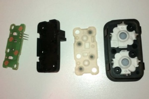
|[[File:W220_A2208211479_dissected.jpg|thumb|none|Button for option code KEYLESS-GO (A2208217251) dissected.]] | |[[File:W220_A2208211479_dissected.jpg|thumb|none|Button for option code KEYLESS-GO (A2208217251) dissected.]] | ||
|} | |} | ||
== Remote trunk locking (RTL) == | |||
<!-- GF80.20-P-0007A, Remote trunk locking (RTL) function, 21.5.99 | |||
MODELS 215, 220 with CODE (881b) Remote trunk locking (RTL) --> | |||
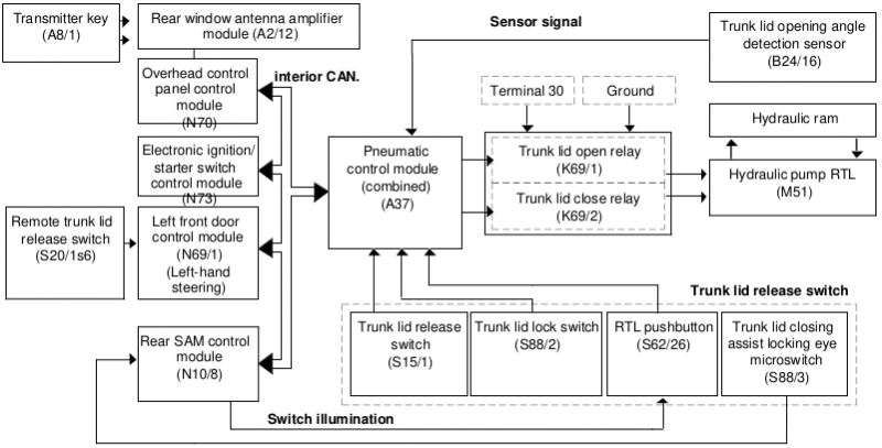
[[File:W220_RTL_scheme.png|800px]] | |||
'''Function overview''' | |||
The remote trunk lid locking (RTL) function in comparison to | |||
remote trunk release (RTR) represents an extension to operating | |||
convenience. Remote trunk locking (RTL) makes it possible to | |||
open and close the trunk lid hydraulically. Models fitted with | |||
remote trunk locking (RTL) are equipped with additional hydraulics, | |||
a sensor and additional operating switches. The location and | |||
networking of the electric components corresponds to the | |||
conditions prevalent in the remote trunk release (RTR) feature. | |||
The extensions in the remote trunk locking (RTL) as compared | |||
with the remote trunk release (RTR) are highlighted in the block diagram. | |||
More detailed information can be ascertained from the reference table that follows. | |||
Hydraulic opening of the trunk lid can be started with the following controls: | |||
* Via radio using the transmitter key (A8/1) | |||
* From inside the car by means of the remote trunk lid release switch (S20/1s6) | |||
* At the trunk lid using the trunk lid release switch (S15/1) | |||
The trunk lid can be opened in this way as far as the end stop. | |||
The opening movement can also be stopped, however, at any desired point and also continued again. | |||
As of 06/00: opening angle limitation: | |||
If the remote trunk lid release switch (S20/s16) is operated continuously for 5 seconds when the trunk lid is closed, | |||
the opening angle limitation is activated - and is deactivated if the remote trunk lid release switch (S20/s16) is operated again for another 5 seconds. | |||
When the function is active, the trunk lid opens as far as the defined position. | |||
Hydraulic closing of the trunk lid is possible by means of the following switches: | |||
* From inside the car by means of the remote trunk lid release switch (S20/1s6) | |||
* At the trunk lid using the RTL pushbutton (S62/26) | |||
For safety reasons, it is not possible to close the trunk lid by means of the remote control using the transmitter key (A8/1). | |||
During the hydraulic closing operation, the hydraulic system | |||
closes the trunk lid just far enough to enable the trunk lid to | |||
automatically engage in the catch as a result of its own weight. | |||
The RTL hydraulic pump (M51) is switched off before the trunk lid | |||
engages in the catch. The power closing system then performs the | |||
final closing of the trunk lid. | |||
The entire control process for the opening and closing functions is | |||
conducted by the pneumatic control module (combined) (A37). | |||
The pneumatic control module (combined) (A37) scans the trunk | |||
lid opening angle detection sensor (B24/16) and is actuated via the | |||
* trunk lid open relay (K69/1) and | |||
* trunk lid close relay (K69/2) | |||
and the hydraulic pump (RTL) (M51). | |||
The two relays are responsible for actuating the electric motor in the hydraulic pump | |||
(RTL) (M51), switching it on and off as well as changing its direction of rotation. | |||
When switched off the two hydraulic pump (RTL) (M51) terminals | |||
are connected to ground. To open the trunk lid a hydraulic pump | |||
(M51) terminal is switched from ground to terminal 30 by the trunk | |||
lid open relay (K69/1). When closing, the trunk lid close relay | |||
(K69/2) switches the corresponding connection at M51 from ground | |||
to terminal 30. | |||
The hydraulic pump (RTL) (M51) builds up the pressure for the | |||
hydraulic ram. A multiple-jointed hinge is used to divert the | |||
straight-line motion of the hydraulic ram into a rotary movement, | |||
with the result that the trunk lid can be hydraulically opened and | |||
closed. | |||
The weight of the trunk lid is relieved through means of two | |||
installed gas-filled telescopic struts. | |||
Safety mechanism: | |||
With the trunk lid opening angle detection sensor (B24/16) the | |||
pneumatic control module (combined) (A37) controls the limit | |||
switch position and the hydraulic operation of the trunk lid. The | |||
hydraulic pump RTL (M51) is switched off when the specified limit | |||
stop angle position is reached. | |||
With the aid of the trunk lid opening angle detection sensor | |||
(B24/16) the pneumatic control module (combined) (A37) analyzes | |||
not only the actual opening angle of the trunk lid, but it also | |||
registers any changes in speed in trunk lid movement. If the trunk | |||
lid encounters an obstacle or if a manual intervention takes place, | |||
the speed of the trunk lid is altered. In such an event the | |||
pneumatic control module (combined) (A37) stops the hydraulic | |||
opening motion and reverses the trunk lid's direction of movement | |||
during the closing procedure. | |||
Manual operation of the trunk lid is also possible in an | |||
emergency, but necessitates greater physical effort as the | |||
hydraulic system also has to be moved. The trunk lid | |||
opening angle detection sensor (B24/16) does not require any | |||
recalibration after a manual intervention. | |||
For safety reasons, the pneumatic control module (combined) | |||
(A37) switches the hydraulic pump RTL (M51) off after a | |||
maximum of two minutes continuous operation. | |||
=== Arrangement of hydraulic components === | |||
<!-- GF80.20-P-0007-01A, Remote trunk locking (RTL) arrangement of hydraulic components | |||
Models 215, 220 with code 881b (trunk lid remote control) --> | |||
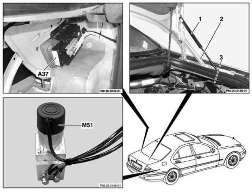
{| | |||
|[[File:W220_RTL_arrangement_of_hydraulic_components.jpg|500px]] | |||
|Shown on model 220: | |||
* 1 - Gas-filled telescopic strut | |||
* 2 - Multiple-jointed hinges | |||
* 3 - Hydraulic ram | |||
* A37 - Pneumatic control module (combined) | |||
* M51 - Hydraulic pump RTL | |||
|} | |||
=== Hydraulic pump === | |||
<!-- GF80.20-P-4115A, Trunk lid remote closing hydraulic pump position/task/design, 12.8.99 | |||
MODELS 215, 220 with CODE (881b) Remote trunk locking (RTL) --> | |||
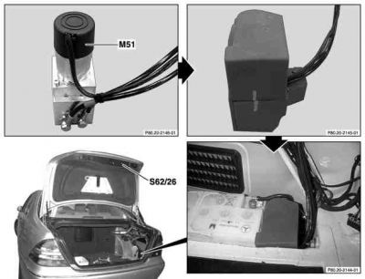
{| | |||
|[[File:W220_RTL_hydraulic_pump.jpg|400px]] | |||
|Shown on model 220: | |||
* M51 - Hydraulic pump RTL | |||
* S62/26 - RTL pushbutton | |||
|} | |||
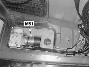
On model 215 the hydraulic pump RTL (M51) is located below the battery. | |||
On model 220 the hydraulic pump RTL (M51) is located in a foam padding in the trunk at bottom right. | |||
{| | |||
|[[File:W220_hydraulic_pump_model_215.jpg|thumb|none|Hydraulic pump on Model 215]] | |||
|[[File:W220_hydraulic_pump_model_220.jpg|thumb|none|Hydraulic pump on Model 220]] | |||
|} | |||
The function of the pump is the supply of pressure for hydraulic ram for hydraulic opening and closing of the trunk lid. | |||
The pump consists of: | |||
* Hydraulic pump with fluid reservoir | |||
* One power supply cable for the hydraulic pump | |||
* Two hydraulic lines | |||
<!-- AR88.50-P-5070N , Removing and installing hydraulic pump for trunk lid remote control, 24.11.00 | |||
MODEL 215, 220 with CODE (881b) Trunk lid remote control (RTL) --> | |||
Removing, installing: | |||
# Withdraw ignition key | |||
# Remove paneling in trunk. Right side only. | |||
# Remove battery (Only model 215) | |||
# Remove cover in battery frame (Only model 215) | |||
# Remove hydraulic pump protective cap (Only model 220) | |||
# Unclip hydraulic cylinder | |||
# Disconnect electric connector on hydraulic pump (M51) | |||
# Remove hydraulic pump (M51) from protective cap. Installation: Replace cable strap. | |||
# Install in the reverse order | |||
=== Hydraulic ram === | |||
<!-- GF80.20-P-4111A, Hydraulic ram position/task/design, 21.5.99 | |||
MODELS 215, 220 with CODE (881b) Remote trunk locking (RTL) --> | |||
{| | |||
|[[File:W220_RTL_hydraulic_ram.jpg|400px]] | |||
|Shown on model 220: | |||
* 1 - Hydraulic ram | |||
|} | |||
Hydraulic ram has two hydraulic lines and is located in trunk behind upper right paneling. | |||
Its task is exertion of forces on to the multiple-jointed hinge for the hydraulic opening and closing of the trunk lid. | |||
=== Trunk lid opening angle detection sensor === | |||
<!-- GF80.20-P-4113A | |||
Trunk lid opening angle detection sensor position/task/design/function, 19.5.99 | |||
MODELS 215, 220 with CODE (881b) Remote trunk locking (RTL) --> | |||
{| | |||
|[[File:W220_Trunk_lid_opening_angle_detection_sensor.jpg|500px]] | |||
|Shown on model 220: | |||
* B24/16 - Trunk lid opening angle detection sensor | |||
* ''(The left-hand photo depicts the position on an opened fender at the rear right.)'' | |||
|} | |||
The sensor is located in the trunk at right below the multiple-jointed hinge. | |||
The sensor's functions are: | |||
* Recording of trunk lid opening angle | |||
* Recording of speed changes in trunk lid in event of malfunction | |||
The sensor consists of: | |||
* Plastic rod serving as connection to multiple-joint hinge | |||
* Potentiometer with electric connection to pneumatic control module (combined) (A37) | |||
=== Resources === | === Resources === | ||
{| | {| | ||
|{{#ev:youtube|https://www.youtube.com/watch?v=FsPy2ugC3X4|320|left| | |{{#ev:youtube|https://www.youtube.com/watch?v=FsPy2ugC3X4|320|left||frame}} | ||
|{{#ev:youtube|https://www.youtube.com/watch?v=RQFL8zWm-U0|320|left| | |{{#ev:youtube|https://www.youtube.com/watch?v=RQFL8zWm-U0|320|left||frame}} | ||
|{{#ev:youtube|https://www.youtube.com/watch?v=z3dB4gPKV70|320|left||frame}} | |||
|{{#ev:youtube|https://www.youtube.com/watch?v=0DZt7S9d_mc|320|left||frame}} | |||
|} | |} | ||
| Line 414: | Line 617: | ||
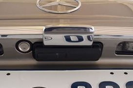
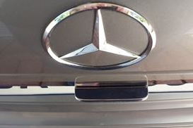
==Retractable Trunk Lid Grip== | ==Retractable Trunk Lid Grip== | ||
[[Facelift]] vehicles without option code [[ | [[Facelift]] vehicles without option code [[Option_codes#881_-_REMOTE_TRUNK_LOCKING|881 - REMOTE TRUNK LOCKING]] have a hidden handle which appears whenever the trunk lid is opened. | ||
The handle is chrome plated and is pneumatically controlled. | |||
It is called the Retractable Trunk Lid Grip (RTG). | |||
The Retractable Trunk Lid Grip (RTG) is used to pull down the | The Retractable Trunk Lid Grip (RTG) is used to pull down the trunk lid for easy closing. | ||
According to M-B the hidden handle was provided to avoid the operator having to touch a wet handle in inclement conditions. | According to M-B the hidden handle was provided to avoid the operator having to touch a wet handle in inclement conditions. | ||
STAR [[DAS]] refers to it as the "dirt free handle". | |||
{| | |||
[[File:W220 Boot Trunk Retractable Trunk Lid Grip in | |[[File:W220 Boot Trunk Retractable Trunk Lid Grip in Hidden Position.jpg|thumb|none|RTG in hidden (retracted) position.]] | ||
|[[File:W220 Boot Trunk Retractable Trunk Lid Grip in Extended Position.JPG|thumb|none|RTG in open (extracted) position]] | |||
|[[File:W220 Boot Trunk Retractable Trunk Lid Grip in Extended Position2.JPG|thumb|none|RTG in open (extracted) position]] | |||
[[File:W220 Boot Trunk Retractable Trunk Lid Grip in Extended | |} | ||
===Opening trunk=== | |||
When the trunk lid is opened by either remote control on the key fob, using the driver's door trunk release switch or pressing the switch on the trunk lid, | |||
the Pneumatic System Equipment (PSE) Pump applies positive pressure to the latch mechanism which unlocks the latch, | |||
releasing the lid which fully opens and also extends the Retractable Trunk Lid Grip (RTG) handle. | |||
The RTG stays in the extended position until the trunk is closed. | |||
There should be no hissing sound of air escaping during this operation. | |||
If there is a hissing sound for even one to two seconds see the Issues section below. | |||
===Closing trunk=== | |||
When the trunk lid is manually closed by pulling down on the RTG Handle until the latch goes click, | |||
the PSE applies positive pressure to the latch mechanism and pulls the lid closed. | |||
Six seconds later the RTG is moved to the retracted position by the PSE pump applying negative pressure to the latch mechanism. | |||
Note, if the RTG has a leakage issue and a hissing sound of air escaping can be heard the RTG handle can take much longer (17s has been observed) to retract. | |||
The positive and negative pressures required for the pneumatic functions are obtained from the [[Pneumatic System Equipment (PSE) Pump]] and specifically the 'HECK' port. | |||
==Locking Mechanism Actuator== | ==Locking Mechanism Actuator== | ||
| Line 483: | Line 695: | ||
====Spare parts==== | ====Spare parts==== | ||
These are part numbers of parts | These are part numbers of parts that build up the locking mechanism. | ||
Unfortunately, | Unfortunately, some of these parts are not listed in EPC catalog and hence cannot be ordered separately. | ||
* Vacuum | * Vacuum solenoid valve (A2308000178) | ||
{| | {| | ||
|[[File:A2308000178_front.jpg|thumb|none|A2308000178 (front).]] | |[[File:A2308000178_front.jpg|thumb|none|A2308000178 (front).]] | ||
| Line 492: | Line 704: | ||
|} | |} | ||
* | * Unlock actuator (A2208000275) | ||
[[File:A2208000275_zoom.jpg|thumb|none]] | {| | ||
|[[File:A2208000275_zoom.jpg|thumb|none|Unlock actuator (A2208000275).]] | |||
|[[File:A2208000275_pressurized.jpg|thumb|none|Unlock actuator (A2208000275) pressurized.]] | |||
|} | |||
* | * Close & lock actuator (A2208000575 - EUR 52) | ||
[[File:A2208000575.jpg|thumb|none]] | {| | ||
|[[File:A2208000575.jpg|thumb|none|Lock actuator (A2208000575).]] | |||
|[[File:A2208000575_pressurized.jpg|thumb|none|Lock actuator (A2208000575) pressurized.]] | |||
|} | |||
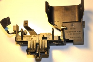
* Latch mechanism pre-facelift (A2208000478) | |||
{| | |||
|[[File:A2208000478.jpg|thumb|none|Latch mechanism pre-facelift (A2208000478).]] | |||
|} | |||
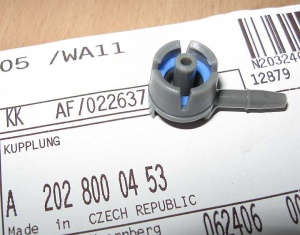
* Clutch (A2028000453) | |||
[[File:A2028000453_clutch.jpg|thumb|none|Clutch (A2028000453).]] | |||
===Function=== | ===Function=== | ||
| Line 502: | Line 728: | ||
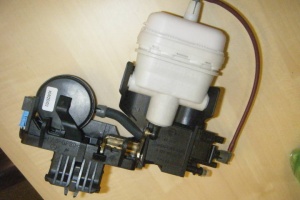
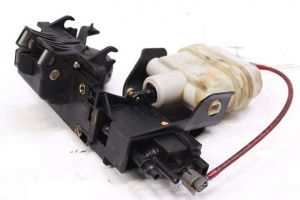
The Trunk Latch Mechanism has the following functions; | The Trunk Latch Mechanism has the following functions; | ||
* Switch to detect when the trunk lid is closed. It can be identified by the blue coloured electrical connector (with wires | * Switch to detect when the trunk lid is closed. It can be identified by the blue coloured electrical connector (with wires brown, brown/black). The switch is electrically open, i.e., high resistance when the trunk lid is either partially closed (first click) or fully closed. The switch is electrically zero resistance when the trunk lid is open. | ||
* Pneumatic actuator (white) to pull the trunk lid fully closed after the lid is placed manually in the partially closed position. | * Pneumatic actuator (white) to pull the trunk lid fully closed after the lid is placed manually in the partially closed position. | ||
* Pneumatic actuator (black) which is commonly referred to as a | * Pneumatic actuator (black) which is commonly referred to as a "puck" which releases the latch mechanism to unlock the trunk lid which thus allowing it to open. | ||
* Remote opening of the trunk lid via two solenoid valves which can be identified by the black coloured electrical connector (with wires | * Remote opening of the trunk lid via two solenoid valves which can be identified by the black coloured electrical connector (with wires brown, brown/blue). The solenoid valves are normally unenergised, passing pressure (if any) to the white "close & lock" pneumatic actuator. When a remote open command is given, for example by the button on the remote key fob, +12V is applied to the solenoid valves for 1 second which energises both valves and passes pressure to the black "unlock" pneumatic "puck" actuator which unlocks the trunk lid and allows it to open. | ||
A detailed description of the opening and closing sequences follows: (Reference: HECK function on [[Pneumatic System Equipment (PSE) Pump]]). | A detailed description of the opening and closing sequences follows: (Reference: HECK function on [[Pneumatic System Equipment (PSE) Pump]]). | ||
* When the | * When the trunk lid is closed manually to the first position as identified by a loud click, the PSE HECK port provides +ve pressure (27KPa or 4psi) to the trunk lid solenoid valve assembly and hence to the large white actuator which pulls the boot closed tightly, then the PSE HECK port changes to –ve pressure (19”Hg vacuum), which retracts the RTG handle (if installed), then returns the line to atmospheric pressure. | ||
* When the | * When the trunk lid is commanded to open either by remote control on the key fob, by pressing the trunk lid button, or by pulling the internal trunk lid release button on the driver's door, the PSE HECK port provides +ve pressure (27KPa or 4psi) to the trunk lid solenoid valve assembly and +12V is applied to the solenoid valves and hence the pressure is passed to the small black actuator which opens the locking latch, thus releasing the lid which fully opens. +ve Pressure is also applied to the RTG Handle, which extends the Handle. After all this is finished the pneumatic line returns to atmospheric pressure. | ||
==== Closing function ==== | ==== Closing function ==== | ||
| Line 518: | Line 744: | ||
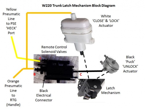
When the lock reaches half-closed position, the PSE pump will give positive pressure to input line (yellow). | When the lock reaches half-closed position, the PSE pump will give positive pressure to input line (yellow). | ||
Electrically controlled solenoid valve will send positive pressure to output port B. | Electrically controlled solenoid valve will be off, which will send positive pressure to output port B. | ||
This will actuate white "close & lock" actuator that will push the lock to fully-closed position. | This will actuate the white "close & lock" actuator that will push the lock to fully-closed position. | ||
Approximately 6 seconds after the lock is fully closed, a negative pressure will be applied to the input line (yellow). | Approximately 6 seconds after the lock is fully closed, a negative pressure will be applied to the input line (yellow). | ||
If the vehicle is equipped with | If the vehicle is equipped with Retractable Trunk Lid Grip (RTG), the negative pressure (vacuum) | ||
will move the handle to the retracted position. | will move the handle to the retracted position. | ||
| Line 527: | Line 753: | ||
When the trunk lid is opened through the [[SmartKey]] or push button, | When the trunk lid is opened through the [[SmartKey]] or push button, | ||
the PSE pump will give positive pressure to input line (yellow). | the PSE pump will give positive pressure to input line (yellow). | ||
Electrically controlled solenoid valve will | Electrically controlled solenoid valve will become energized, which will cause the pressure to be sent to output port C. | ||
This will cause the lock to be released and moved to open position. | |||
If the trunk is opened using mechanical key, the trunk release rod connected to trunk latch will release the lock to open position. | If the trunk is opened using mechanical key, the trunk release rod connected to trunk latch will release the lock to open position. | ||
The positive and negative pressures required for the pneumatic control of the trunk lid functions are generated by the [[Pneumatic System Equipment (PSE) Pump]] | The positive and negative pressures required for the pneumatic control of the trunk lid functions are generated by the [[Pneumatic System Equipment (PSE) Pump]]. | ||
==Hazard Warning Triangle== | |||
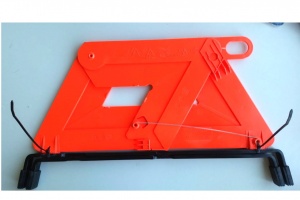
A common issue with hazard warning triangle is plastic triangle breakage from metal stand. | |||
Broken triangle can be fixed with super glue and cable ties (fixation with cable ties requires drilling small hole in one side of the plastic triangle). | |||
[[File:W220_broken_warning_triangle_fixed.jpg|thumb|none|Broken warning triangle fixed]] | |||
==Issues== | ==Issues== | ||
Common issues relating to the trunk/boot lid functions are | Common issues relating to the trunk/boot lid functions are: | ||
* Hissing | * Hissing sound on trunk opening or closure can occur due to a leak in either the: | ||
** | ** Retractable Trunk Lid Grip (RTG); | ||
** Trunk | ** Trunk latch control solenoid valve module; | ||
** Cracked or broken pneumatic line where it enters the | ** Cracked or broken pneumatic line where it enters the trunk. | ||
* Broken or | * Broken or failed pneumatic actuators. | ||
* Broken wires in | * Broken wires in pneumatic solenoid valves. | ||
* Cracked or broken pneumatic lines. | * Cracked or broken pneumatic lines. | ||
* Leakage of water into the trunk because the power closing assist fails to pull the lid closed completely. | * Leakage of water into the trunk because the power closing assist fails to pull the lid closed completely. | ||
* Cannot open the trunk when the battery is dead. | * Cannot open the trunk when the battery is dead. | ||
| Line 554: | Line 785: | ||
* Then put it back in and then test the Trunk/Boot functions. | * Then put it back in and then test the Trunk/Boot functions. | ||
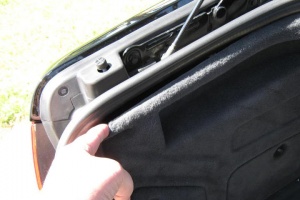
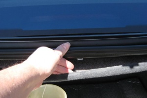
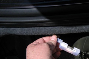
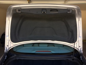
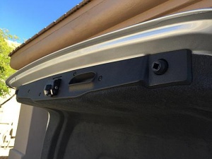
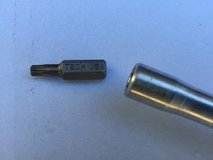
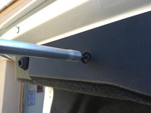
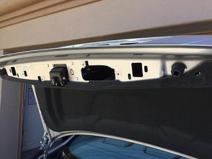
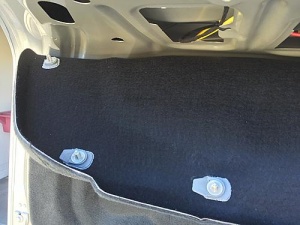
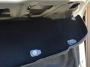
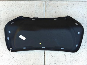
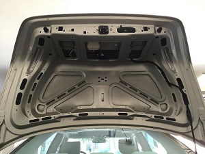
=== DIY | === DIY - Removing trunk lid lining === | ||
<!-- http://www.benzworld.org/forums/w220-s-class/2532833-repair-part-220-750-0684-trunk.html --> | <!-- http://www.benzworld.org/forums/w220-s-class/2532833-repair-part-220-750-0684-trunk.html --> | ||
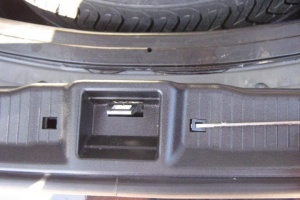
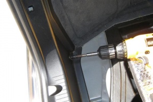
| Line 573: | Line 804: | ||
|} | |} | ||
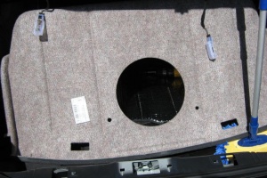
=== DIY | === DIY - Removing trunk lining === | ||
<!-- http://www.benzworld.org/forums/w220-s-class/2000609-less-than-20-usd-gps-antenna.html --> | <!-- http://www.benzworld.org/forums/w220-s-class/2000609-less-than-20-usd-gps-antenna.html --> | ||
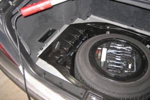
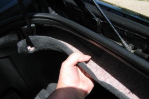
{| | {| | ||
| Line 593: | Line 824: | ||
|} | |} | ||
=== DIY - | === DIY - Removing trunk locking mechanism actuator === | ||
* Remove the trunk lid lining. | |||
* | * Remove trunk release rod. | ||
* Remove | |||
* Note that the rod end is placed between one black plastic piece that has screw thread on it and another piece that is like a small latch door. | * Note that the rod end is placed between one black plastic piece that has screw thread on it and another piece that is like a small latch door. | ||
* Mark the position of the actuator rod with masking tape. | * Mark the position of the actuator rod with masking tape. | ||
[[File:W220 Masking Tape Showing Position of Trunk Actuator Lever.JPG| | [[File:W220 Masking Tape Showing Position of Trunk Actuator Lever.JPG|thumb|none|Masking type applied to mark rod depth setting.]] | ||
* | * '''Caution:''' It is difficult to remove the actuator rod out of the trunk locking mechanism without breaking the plastic that surrounds it. Be careful as if the rod is not replaced correctly and securely, the trunk can lock and may not be openable with either the key or with the remote. | ||
* The latch door can be opened with a wide flat head screwdriver. Carefully apply a strong steady force. | * The latch door can be opened with a wide flat head screwdriver. Carefully apply a strong steady force. | ||
* Once the latch piece "swings away", the metal rod can be pried out of the plastic piece. The key is to be gentle and patient. | * Once the latch piece "swings away", the metal rod can be pried out of the plastic piece. The key is to be gentle and patient. It is a good idea to place a spacer behind the rod to hold it in place when applying finger pressure to the plastic tab. | ||
[[File:W220 Trunk Actuator Lever Removed from Tab.JPG| | [[File:W220 Trunk Actuator Lever Removed from Tab.JPG|thumb|none|]] | ||
* Once the rod is released the whole actuator can easily be removed from the trunk lid. It is far easier to attempt a repair on a work bench than with the unit still in the car. | * Once the rod is released the whole actuator can easily be removed from the trunk lid. It is far easier to attempt a repair on a work bench than with the unit still in the car. | ||
* Mark the position of the two Torx screws holding the latch mechanism in place. This makes for easier reinstallation. | * Mark the position of the two Torx screws holding the latch mechanism in place. This makes for easier reinstallation. | ||
[[File:W220 Boot Trunk Lock Mechanism with Marked Screw Positions.JPG| | [[File:W220 Boot Trunk Lock Mechanism with Marked Screw Positions.JPG|thumb|none|]] | ||
* Remove the two Torx screws and allow the whole actuator assembly to hang down into the trunk. | * Remove the two Torx screws and allow the whole actuator assembly to hang down into the trunk. | ||
[[File:W220 Trunk Latch Actuator Pneumatic Line Colours.JPG| | [[File:W220 Trunk Latch Actuator Pneumatic Line Colours.JPG|thumb|none|]] | ||
* Note the colours of the pneumatic lines and the position of the black and blue electrical connectors before disconnecting them. | * Note the colours of the pneumatic lines and the position of the black and blue electrical connectors before disconnecting them. | ||
* Re-install in reverse order. | |||
* An annoying rattle can be caused by the RTG one way valve (black and white device in the picture below) rattling against the boot lid. It can be securing firmly with plastic ties. | |||
[[File:W220 One Way Valve was Source of Annoying Rattle.JPG|thumb|none|Pneumatic line secured with plastic ties.]] | |||
* Re-install in reverse order | |||
* | |||
[[File:W220 One Way Valve was Source of Annoying Rattle.JPG| | |||
Downloadable pdfs are at reference Post #5: http://www.benzworld.org/forums/w220-s-class/1675592-w220-trunk-lid-hockey-puck-removal.html | <!-- Downloadable pdfs are at reference Post #5: http://www.benzworld.org/forums/w220-s-class/1675592-w220-trunk-lid-hockey-puck-removal.html --> | ||
=== DIY - Welding trunk lid covering holes === | |||
=== DIY | |||
Trunk lid has 7 (pre-[[facelift]]) or 8 ([[facelift]]) holes which are used to attach the trunk covering (9) to the trunk lid. | Trunk lid has 7 (pre-[[facelift]]) or 8 ([[facelift]]) holes which are used to attach the trunk covering (9) to the trunk lid. | ||
It is common to see these holes being a source for moisture and rust inside the trunk lid. | It is common to see these holes being a source for moisture and rust inside the trunk lid. | ||
| Line 650: | Line 858: | ||
|} | |} | ||
=== DIY | === DIY - Repair broken trunk lid actuator pneumatic chambers === | ||
<!-- http://www.benzworld.org/forums/w220-s-class/2532833-repair-part-220-750-0684-trunk.html --> | <!-- http://www.benzworld.org/forums/w220-s-class/2532833-repair-part-220-750-0684-trunk.html --> | ||
| Line 661: | Line 869: | ||
Note the broken plastic tabs on the perimeter of the actuator. | Note the broken plastic tabs on the perimeter of the actuator. | ||
{| | {| | ||
|[[File:A2208000275_cracks.jpg|thumb|none|A2208000275 with cracks on tabs.]] | |||
|[[File:W220 Broken Boot Trunk Lid Pneumatic Actuator.JPG|thumb|none|A2208000275 with completely broken tabs.]] | |[[File:W220 Broken Boot Trunk Lid Pneumatic Actuator.JPG|thumb|none|A2208000275 with completely broken tabs.]] | ||
|[[File:A2208000275_broken.jpg|thumb|none|A2208000275 with separated cap.]] | |[[File:A2208000275_broken.jpg|thumb|none|A2208000275 with separated cap.]] | ||
| Line 677: | Line 886: | ||
|} | |} | ||
[[File:A2208000275_repair_glue.jpg|thumb|none|Repair using glue.]] | |||
=== DIY | {| | ||
|[[File:W220 Trunk Latch Actuator With Reinforcing Wires and Ties Bottom View.JPG|thumb|none|Repair using wire and cable ties.]] | |||
|[[File:W220 Trunk Latch Actuator With Reinforcing Wires and Ties Top View.JPG|thumb|none|Repair using wire and cable ties.]] | |||
|} | |||
Instructions for chamber removal: | |||
* Move the whole assembly to a work bench. | |||
* At the lock mechanism where the rod attaches, take a screw driver or needle nose pliers and gently wedge between rod and plastic slot where the rod attaches. | |||
* Gently pry the rod out of the slot. | |||
* Once the rod is released you can then pull the lock mechanism down so you can access the puck. This isn't hard, but a word of warning! There is a little electrical plug that attaches next to the puck. If you unplug it, make sure your fingers are not next to the lock latch as it will put a death grip on your finger. | |||
* The puck is press fitted into the lock housing and again can be detached by gently prying with a small screwdriver to release. | |||
* Once the puck is detached if the air line is still attached it can be removed if required to bench work the puck. Instead of detaching the airline at the puck just pull the hose off at the attachment point at the puck. It is easy to understand when you get the puck released from the housing. | |||
* Unless you have a replacement puck, then you must attempt to reseal. | |||
* Reseal by compressing the puck then using a two part sealer. Coat the seam around the side of the puck where it was leaking, 360 degrees. | |||
* Let it cure for a few hours. | |||
* Wrap "high speed" tape over the seal. | |||
* Add more tape over the top and bottom to fortify the bond. | |||
=== DIY - Repair broken hose === | |||
A persistent loud hissing noise once you open or close your trunk even for one to two seconds is not normal and usually means that you have a leak in the trunk lock actuator, the RTG actuator, the yellow pneumatic hose or fittings connecting the PSE Pump to the locking mechanism, or the orange pneumatic line or fittings connecting the locking mechanism to the RTG. | |||
It will eventually stop leaking once the leak gets worse. Hopefully the pump will recognise that it is running for too long and will stop working so that it doesn't burn out. | |||
Do not leave it in this condition for too long because when the trunk stops sucking down water can get in and ruin your electronic components in the left side of the trunk behind the panels. | |||
There is also a possibility of damaging the pump due to constant running. | |||
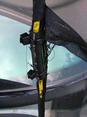
Often the hissing is caused by a crack in the yellow pneumatic line that is located inside the black braided plastic harness which is easily visible on the inside of the trunk towards the rear window. | |||
You can see it when the trunk opens and closes. For whatever reason M-B used a very stiff pipe which cracks easily. | |||
A common mistake is that when you have some aftermarket installation such as a reversing camera, the installer runs their wires alongside the harness, | |||
and adhere their wires to this with the additional strain causing premature failure of the stiff pneumatic line. | |||
A simple fix is to use a rubber hose to cover the crack and seal it with adhesive, sealer, tape and plastic ties. | |||
[[File:W220_Repair_of_Yellow_Trunk_Vacuum_Hose.JPG|thumb|none|Repaired hose.]] | |||
<!-- http://www.benzworld.org/forums/showthread.php?t=1761754 --> | |||
If the hissing is caused by a broken actuator mechanism it is possible to apply a temporary fix by reinforcing the actuators with twitching wire and plastic ties (see other instructions on this page). | |||
But be aware that the forces generated by the PSE Pump are considerable and the best method to achieve a repair is to replace the actuators with new ones. | |||
Second hand actuators will most likely be just as stressed as the broken one you are replacing. | |||
=== DIY - Repair of trunk lid actuator pneumatic solenoid valves=== | |||
In the trunk latch mechanism there are two solenoid valves which distribute the pneumatic pressure to the relevant actuator depending on the required result. | In the trunk latch mechanism there are two solenoid valves which distribute the pneumatic pressure to the relevant actuator depending on the required result. | ||
A common failure mode is for the | A common failure mode is for the control solenoid valve module to crack and leak. | ||
In this example the plugged end of the inlet manifold has cracked. During manufacture a ball bearing was pressed into the manifold to seal it off. With age it has eventually cracked and even though not a large crack, it caused a very loud hissing noise as the air escaped when the trunk lid was opened. | In this example the plugged end of the inlet manifold has cracked. | ||
During manufacture a ball bearing was pressed into the manifold to seal it off. | |||
With age it has eventually cracked and even though not a large crack, | |||
it caused a very loud hissing noise as the air escaped when the trunk lid was opened. | |||
The small crack shown in the example above was easily repaired using super glue and a small hose clamp. | The small crack shown in the example above was easily repaired using super glue and a small hose clamp. | ||
=== DIY | {| | ||
Once the | |[[File:W220 Trunk Remote Control Solenoids Failure Mode Leak.JPG|thumb|none|Crack in the inlet mainfold.]] | ||
* | |[[File:W220 Trunk Remote Control Solenoids Repaired.JPG|thumb|none|Crack repaired.]] | ||
|} | |||
=== DIY - Clean and regrease trunk lid actuator pneumatic solenoid valves=== | |||
Once the trunk lid pneumatic actuator is removed from the vehicle it can be dismantled on the work bench. | |||
* Valve assembly can be withdrawn from latch mechanism by pressing in the two small plastic tabs. Note there is no mechanical coupling between the control solenoids and the latch mechanism even though it looks like there might be. | |||
[[File:A2308000178_release_clips.jpg|thumb|none|Plastic tabs for valve release from latch mechanism.]] | |||
* Remove the top front cover over the electrical connector. | * Remove the top front cover over the electrical connector. | ||
[[File:A2308000178_cover_over_connector.jpg|thumb|none|Top cover over electrical connector.]] | |||
* Then press in two small plastic tabs and remove the top rear cover. | * Then press in two small plastic tabs and remove the top rear cover. | ||
[[File:W220 Trunk Lid Actuator Pneumatic Solenoid Valves 01.JPG|thumb|none| | [[File:W220 Trunk Lid Actuator Pneumatic Solenoid Valves 01.JPG|thumb|none|Disassembled solenoid valve assembly.]] | ||
[[File:W220 Trunk Lid Actuator Pneumatic Solenoid Valves 02.JPG|thumb|none|Closeup of coils and seals.]] | [[File:W220 Trunk Lid Actuator Pneumatic Solenoid Valves 02.JPG|thumb|none|Closeup of coils and seals.]] | ||
* Before | * Before reassembly check the electrical pneumatic solenoid valves. | ||
* Reassemble in the reverse order but apply silicon dielectric or vacuum grease to the pneumatic seals before assembly. | * Reassemble in the reverse order but apply silicon dielectric or vacuum grease to the pneumatic seals before assembly. | ||
===DIY | ===DIY - Check electrical performance of trunk lid pneumatic solenoid valves=== | ||
The electrical circuit diagram is very simple with the two coils just connected in parallel. A diode is also connected across the coils to reduce current surge when the coils are switched off. (Here is the theory: The magnetic energy stored in energised coils can generate a large spark across the operating switch when it is opened and consequently burn the electrical contacts in the switch. A diode provides a path for this excess energy to dissipate harmlessly.) The downside of having a diode in the circuit is that the electrical contacts are now polarised and correct polarity of any applied test voltage must be observed otherwise the diode will burn out. This just means that the '+' and '-' signs on the next diagram ''' | The electrical circuit diagram is very simple with the two coils just connected in parallel. A diode is also connected across the coils to reduce current surge when the coils are switched off. (Here is the theory: The magnetic energy stored in energised coils can generate a large spark across the operating switch when it is opened and consequently burn the electrical contacts in the switch. A diode provides a path for this excess energy to dissipate harmlessly.) The downside of having a diode in the circuit is that the electrical contacts are now polarised and correct polarity of any applied test voltage must be observed otherwise the diode will burn out. This just means that the '+' and '-' signs on the next diagram '''must be observed''' when applying a 12 Volt DC test voltage. | ||
[[File:W220 Trunk Lid Actuator Pneumatic Solenoid Valves 03.JPG|thumb|none|Circuit | [[File:W220 Trunk Lid Actuator Pneumatic Solenoid Valves 03.JPG|thumb|none|Circuit diagram of solenoid valves.]] | ||
Each valve coil has a resistance of 36 Ohms, therefore the combined resistance for the two coils in parallel as measured across the black electrical connector is 18 Ohms. Note that there is a diode across the coils so that may influence the measurement obtained with some Digital Multi Meters. | Each valve coil has a resistance of 36 Ohms, therefore the combined resistance for the two coils in parallel as measured across the black electrical connector is 18 Ohms. Note that there is a diode across the coils so that may influence the measurement obtained with some Digital Multi Meters. | ||
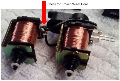
===DIY | After many opening and closing of the trunk the wires between the two pneumatic solenoid valves fatigue and break. | ||
They can be easily resoldered once the mechanism is dismantled. | |||
[[File:W220 Trunk Lid Actuator Pneumatic Solenoid Valves Check for Broken Wires Here.JPG|500px]] | |||
===DIY - Check pneumatic performance of trunk lid pneumatic solenoid valves=== | |||
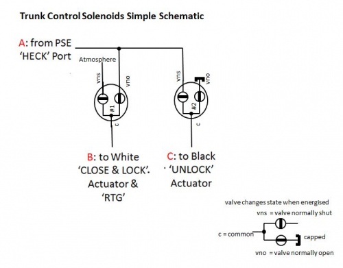
The first two schematics show the inlet, outlet lines and how they are connected to the control solenoids. | |||
[[File:W220 Trunk Control Solenoids Schematic 01.JPG|500px]] | |||
[[File:W220 Trunk Control Solenoids Schematic 02.JPG|500px]] | |||
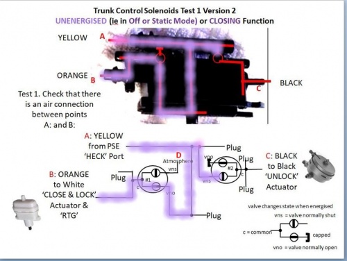
Test 1 is made with the solenoid valves unenergised, which is the normal or static state used to close the trunk. | |||
[[File:W220 Trunk Control Solenoids Function Unenergised 03.JPG|500px]] | |||
Test 1 Version 2 is easier to follow. | |||
[[File:W220 Trunk Control Solenoids Function Unenergised 03 Version 2.JPG|500px]] | |||
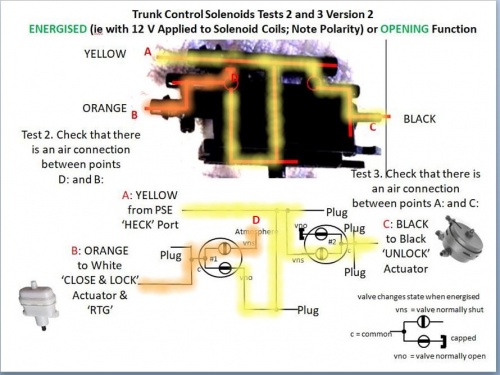
Tests 2 and 3 are made with the solenoid valves energised (polarised 12V), and is the state used to open the trunk. | |||
[[File:W220 Trunk Control Solenoids Function Energised 04.JPG|500px]] | |||
Tests 2 and 3 Version 2 is easier to follow. | |||
[[File:W220 Trunk Control Solenoids Function Energised 04 Version 2.JPG|500px]] | |||
===DIY - Changing time delay in trunk opening=== | |||
When the trunk release button is pressed in order to open the trunk there is a time delay before the trunk actually opens. It is possible to change the time delay that occurs using STAR. The default time is 0.25 seconds. | When the trunk release button is pressed in order to open the trunk there is a time delay before the trunk actually opens. It is possible to change the time delay that occurs using STAR. The default time is 0.25 seconds. | ||
Latest revision as of 18:27, 6 September 2023
Emergency Opening
Trunk opening with a dead battery
A completely dead battery prevents the boot lid from being electrically opened. A jump start is not possible if you cannot access the battery as the W220 does not have accessible jump ports.
If the trunk is locked and the battery is dead try these techniques for opening the trunk lid.
Solution 1: Extract the mechanical key from the SmartKey and use it to open the trunk.
Solution 2: If the mechanical key doesn't work you may have to charge the battery prior to jump starting the car.
|
Trunk opening without a key (pre-facelift)
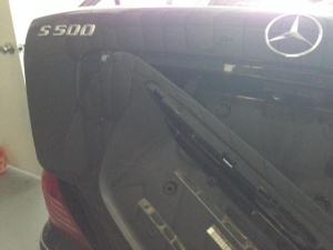
To open the trunk if for some reason it cannot be opened using smartkey or mechanical key, you can use this method which will cause only minor damage of the lid covering.
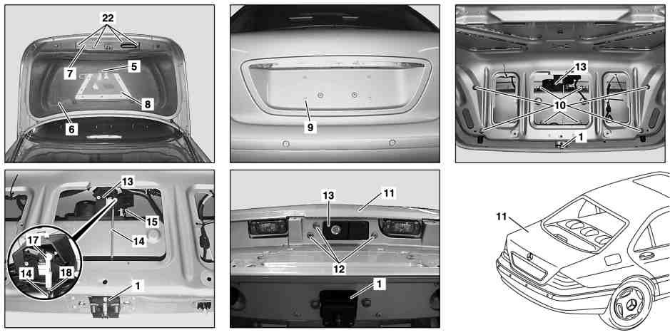
- 1. Detach the licence plate from the trunk lid covering.
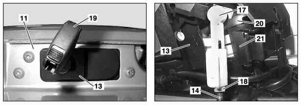
- 2. The covering (9) is a big plastic part mounted on the lid. Remove the covering. You will see two screws in the middle of covering (9). Remove them. You have to remove covering by force using plastic molding remover tool. Note, that there are 7 bolts (10) that are tightened from the inside to hold the covering (9) in place. You will damage plastic housing for these bolts in the covering. However, it is very common to see these housings already damaged. Furthermore, the covering holds to the lid just fine only using the two central screws.
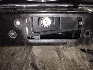
- 3. After covering is removed you will see three T30 torx bolts (12) holding the trunk lid handle. Unscrew them.
- 4. Push the whole trunk lid handle inside through the hole while pushing the button.
- 5. You will hear the pop noise. Trunk lid is open.
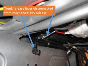
- 6. In case the release rod (14) that connects the trunk lid lock (1) to the trunk lid handle (13) is disconnected, you can use a needled nose pliers to release the rod and open the trunk.
 |
 |
 |
Trunk opening without a key (facelift)
To open the trunk if for some reason it cannot be opened using smartkey or mechanical key, you can use this method which will cause only minor damage of the lid covering.
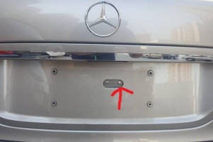
- 1. Detach the licence plate from the trunk lid covering.
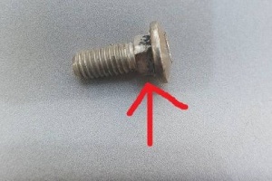
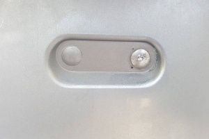
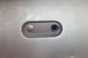
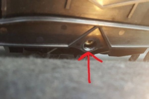
- 2. Remove the covering. The covering is a big plastic part mounted on the lid. Note, that there are 8 clips and one bolt in the center tightened from the inside that hold the covering in place. You have to drill off the head of center bolt holding the covering. This bolt is not crucial, since the covering holds to the lid just fine using only the clips. It is possible that in the process of drilling, the covering hole will get wider and the screw will get loose instead of losing its flat head.
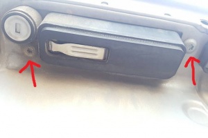
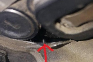
- 3. After trunk lid covering is removed the lock and its 2 screws can be reached. After loosing them the lock will not fall inside the trunk, but will only move an inch to the left or the right. This is because there is third screw holding the lock in place inside the trunk.
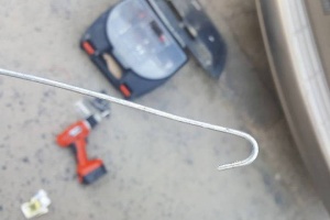
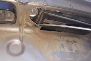
- 4. Now the trunk release rod can be observed. It must be catched with a pincer or pliers and pulled up. A hook can be used to prevent the rod from sliding out of pliers. After pulling the rod up the trunk lid will open.
 |
 |
 |
 |
 |
 |
 |
 |
 |
 |
Normal Opening
WARNING: A minimum height clearance of 6 ft. (1.85 m) is required to open the trunk lid fully.
Unlocking and opening the trunk lid using SmartKey
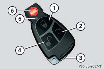
Press and hold trunk lid unlock button (2) on the SmartKey until trunk unlocks and begins to open.
If the trunk lid does not open, it is still locked separately (see below).
Delay in trunk/boot lid opening
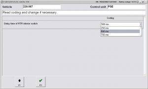
When you press the open trunk button on the SmartKey, it can take anywhere from a quarter of a second to several seconds before the trunk opens. The time delay is adjustable using STAR DAS. See Section 'DIY 9 - Procedure to Change Time Delay in Trunk Opening' below.
Opening the trunk lid from the inside
You can open the trunk from the inside if the vehicle is stationary.
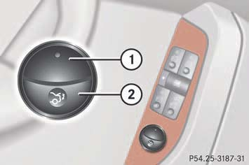
The switch is located on the driver's door.
- (1) Indicator lamp
- (2) Remote trunk lid release switch
Pull remote trunk lid switch (2) until trunk begins to open. The trunk lid opens. The indicator lamp (1) comes on and remains lit until the trunk is closed.
Even with the SmartKey removed from the starter switch or the SmartKey with KEYLESS-GO removed from the vehicle, the remote trunk lid switch can be operated.
If the vehicle was previously centrally locked, the trunk lid will lock automatically when closed. The turn signals will flash three times to confirm locking.
Opening the trunk lid using emergency release
Some W220 S-Class vehicles have an emergency release button so that you do not get trapped inside.
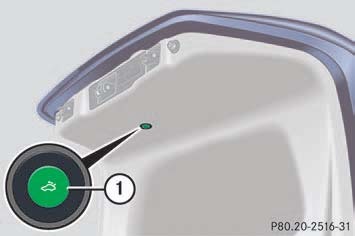
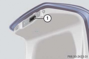
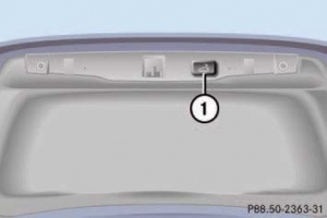
The emergency release button is located on the inside of the trunk lid. Briefly press emergency release button (1). The trunk unlocks and the trunk lid opens. The emergency release button unlocks and opens the trunk while the vehicle is standing or driving. The emergency release button does not open the trunk lid if the vehicle battery is discharged or disconnected.
Illumination of the emergency release button:
- The button will flash for 30 minutes after opening the trunk.
- The button will flash for 60 minutes after closing the trunk.
If the emergency release button is pressed and the vehicle was centrally locked, the exterior lamps will flash and the alarm will sound as the trunk lid opens.
Opening the trunk lid from the outside
 |
 |
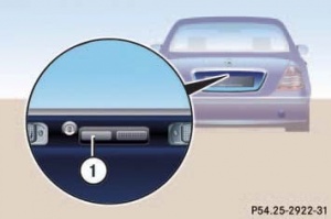
The trunk lid open button is located in the rear license plate recess. Press the outer left-hand side of trunk lid button (1). The trunk lid opens.
Vehicles with KEYLESS-GO: If the vehicle was previously centrally locked, the trunk lid will lock automatically after closing it.
Normal Closing
WARNING: Do not place the SmartKey in the open trunk. You may lock yourself out.
Vehicles with KEYLESS-GO: To prevent a possible inadvertent lockout, the trunk lid will open automatically if a SmartKey with KEYLESS-GO is recognized inside the vehicle or in the trunk.
Closing the trunk lid using handle
 |
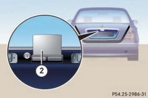 |
On vehicles without option code 881 - REMOTE TRUNK LOCKING the trunk lid can be lowered by pulling firmly on handle (1) or using the extending handle (Retractable Trunk Grip (RTG)) built into the trunk lid handle (2) (available only on facelift vehicles). Push the trunk lid down gently at the extending handle (2) until it engages into the lock. The extending handle (2) is retracted after a few seconds. The power closing assist automatically ensures that the lid is pulled closed completely.
Remote Closing
On vehicles with option code 881 - REMOTE TRUNK LOCKING the trunk lid can be opened and closed by a press of button.
If the trunk lid comes into contact with an object while closing (e.g. luggage that has been piled too high) in the upper motion sequence, the closing procedure is stopped and the trunk reopens slightly.
The closing procedure can be stopped at any time by pressing the trunk lid closing switch (on the driver's door), the trunk lid closing switch (1), or the "trunk lid unlock" button on the SmartKey.
Closing from the outside
 |
 |
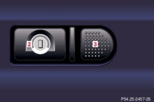
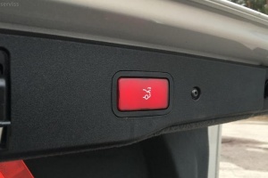
Press trunk lid closing switch (1) briefly. The trunk lid closes.
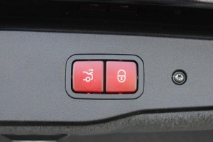
On vehicles with trunk lid closing system and KEYLESS-GO, you can close the trunk lid and lock the vehicle simultaneously using the second button on the switch.
 |
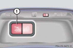 |
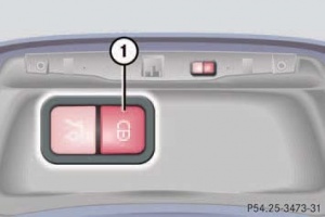 |
Make sure you have the SmartKey with KEYLESS-GO with you. Press trunk lid closing switch (1) (in the second picture) briefly. The vehicle is locked and the trunk lid closes automatically. The turn signals flash three times to confirm locking.
Closing from the inside
The trunk lid can be closed from the inside using the opening switch if the vehicle is stationary.
Press remote trunk lid switch (2) until the indicator lamp (1) goes out and trunk lid is closed. To interrupt the closing procedure release remote trunk lid switch (2).
Limiting opening height
The trunk lid opening height can be limited when transporting goods on a roof rack (e.g. presence of an MB sport luggage container).
When activated, the trunk lid opens to approximately the height of the roof edge.
You can activate the limiting opening height of trunk lid using the control system or menu in instrument cluster.
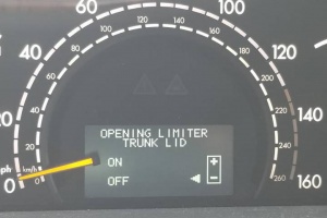 |
Nomalizing opening height
In case trunk fails to open to its full height, normalization of opening height is necessary.
Trunk opening has a reset procedure using the switch on the driver's door panel. Instead of listening for the click sound, continue to hold the switch for an additional 15 seconds. Do this with the trunk in the fully opened position, and then again from the closed position. Sometimes it is necessary to go through two full open/close cycles to get the trunk opening height to be reset correctly.
Alternatively, trunk lid opening height can be normalized using appropriate adaptation functionality under PSE module in DAS.
Parts
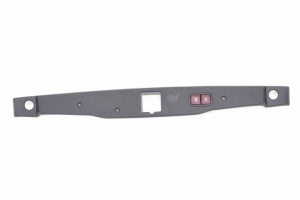
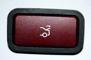 |
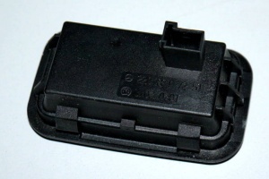 |
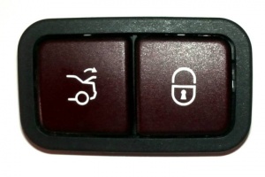 |
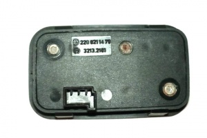 |
 |
Remote trunk locking (RTL)
Function overview
The remote trunk lid locking (RTL) function in comparison to remote trunk release (RTR) represents an extension to operating convenience. Remote trunk locking (RTL) makes it possible to open and close the trunk lid hydraulically. Models fitted with remote trunk locking (RTL) are equipped with additional hydraulics, a sensor and additional operating switches. The location and networking of the electric components corresponds to the conditions prevalent in the remote trunk release (RTR) feature. The extensions in the remote trunk locking (RTL) as compared with the remote trunk release (RTR) are highlighted in the block diagram. More detailed information can be ascertained from the reference table that follows.
Hydraulic opening of the trunk lid can be started with the following controls:
- Via radio using the transmitter key (A8/1)
- From inside the car by means of the remote trunk lid release switch (S20/1s6)
- At the trunk lid using the trunk lid release switch (S15/1)
The trunk lid can be opened in this way as far as the end stop. The opening movement can also be stopped, however, at any desired point and also continued again.
As of 06/00: opening angle limitation: If the remote trunk lid release switch (S20/s16) is operated continuously for 5 seconds when the trunk lid is closed, the opening angle limitation is activated - and is deactivated if the remote trunk lid release switch (S20/s16) is operated again for another 5 seconds. When the function is active, the trunk lid opens as far as the defined position.
Hydraulic closing of the trunk lid is possible by means of the following switches:
- From inside the car by means of the remote trunk lid release switch (S20/1s6)
- At the trunk lid using the RTL pushbutton (S62/26)
For safety reasons, it is not possible to close the trunk lid by means of the remote control using the transmitter key (A8/1).
During the hydraulic closing operation, the hydraulic system closes the trunk lid just far enough to enable the trunk lid to automatically engage in the catch as a result of its own weight. The RTL hydraulic pump (M51) is switched off before the trunk lid engages in the catch. The power closing system then performs the final closing of the trunk lid. The entire control process for the opening and closing functions is conducted by the pneumatic control module (combined) (A37). The pneumatic control module (combined) (A37) scans the trunk lid opening angle detection sensor (B24/16) and is actuated via the
- trunk lid open relay (K69/1) and
- trunk lid close relay (K69/2)
and the hydraulic pump (RTL) (M51). The two relays are responsible for actuating the electric motor in the hydraulic pump (RTL) (M51), switching it on and off as well as changing its direction of rotation.
When switched off the two hydraulic pump (RTL) (M51) terminals are connected to ground. To open the trunk lid a hydraulic pump (M51) terminal is switched from ground to terminal 30 by the trunk lid open relay (K69/1). When closing, the trunk lid close relay (K69/2) switches the corresponding connection at M51 from ground to terminal 30. The hydraulic pump (RTL) (M51) builds up the pressure for the hydraulic ram. A multiple-jointed hinge is used to divert the straight-line motion of the hydraulic ram into a rotary movement, with the result that the trunk lid can be hydraulically opened and closed. The weight of the trunk lid is relieved through means of two installed gas-filled telescopic struts.
Safety mechanism: With the trunk lid opening angle detection sensor (B24/16) the pneumatic control module (combined) (A37) controls the limit switch position and the hydraulic operation of the trunk lid. The hydraulic pump RTL (M51) is switched off when the specified limit stop angle position is reached.
With the aid of the trunk lid opening angle detection sensor (B24/16) the pneumatic control module (combined) (A37) analyzes not only the actual opening angle of the trunk lid, but it also registers any changes in speed in trunk lid movement. If the trunk lid encounters an obstacle or if a manual intervention takes place, the speed of the trunk lid is altered. In such an event the pneumatic control module (combined) (A37) stops the hydraulic opening motion and reverses the trunk lid's direction of movement during the closing procedure.
Manual operation of the trunk lid is also possible in an emergency, but necessitates greater physical effort as the hydraulic system also has to be moved. The trunk lid opening angle detection sensor (B24/16) does not require any recalibration after a manual intervention.
For safety reasons, the pneumatic control module (combined) (A37) switches the hydraulic pump RTL (M51) off after a maximum of two minutes continuous operation.
Arrangement of hydraulic components
|
Shown on model 220:
|
Hydraulic pump
|
Shown on model 220:
|
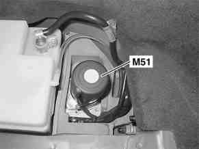
On model 215 the hydraulic pump RTL (M51) is located below the battery.
On model 220 the hydraulic pump RTL (M51) is located in a foam padding in the trunk at bottom right.
 |
 |
The function of the pump is the supply of pressure for hydraulic ram for hydraulic opening and closing of the trunk lid.
The pump consists of:
- Hydraulic pump with fluid reservoir
- One power supply cable for the hydraulic pump
- Two hydraulic lines
Removing, installing:
- Withdraw ignition key
- Remove paneling in trunk. Right side only.
- Remove battery (Only model 215)
- Remove cover in battery frame (Only model 215)
- Remove hydraulic pump protective cap (Only model 220)
- Unclip hydraulic cylinder
- Disconnect electric connector on hydraulic pump (M51)
- Remove hydraulic pump (M51) from protective cap. Installation: Replace cable strap.
- Install in the reverse order
Hydraulic ram
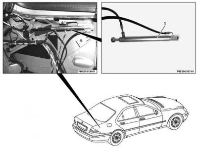
|
Shown on model 220:
|
Hydraulic ram has two hydraulic lines and is located in trunk behind upper right paneling. Its task is exertion of forces on to the multiple-jointed hinge for the hydraulic opening and closing of the trunk lid.
Trunk lid opening angle detection sensor
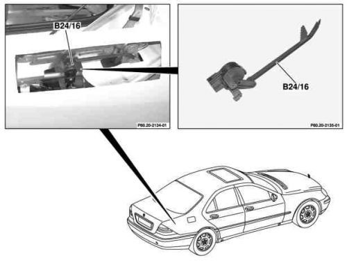
|
Shown on model 220:
|
The sensor is located in the trunk at right below the multiple-jointed hinge.
The sensor's functions are:
- Recording of trunk lid opening angle
- Recording of speed changes in trunk lid in event of malfunction
The sensor consists of:
- Plastic rod serving as connection to multiple-joint hinge
- Potentiometer with electric connection to pneumatic control module (combined) (A37)
Resources
Restricting Access with Additional Locking Mechanism
Vehicles equipped with option code 884 - TRUNK LID ADDITIONAL LOCKING MECHANISM (HZS) have a function permitting the separate locking of the trunk using the mechanical key. If present, this feature can permit you to deny any unauthorized person access to the trunk by locking the trunk separately and leaving the SmartKey less the mechanical key with the vehicle.
To verify the presence of this feature, use the mechanical key to lock the trunk and then attempt to open the trunk by pressing the trunk lid button after the vehicle has been centrally unlocked with the SmartKey.
The lock is located next to the recessed handle.
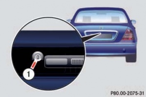
Close the trunk lid. Pull the mechanical key out of the SmartKey. Insert the mechanical key into the trunk lid lock. Turn the mechanical key clockwise to vertical position. The trunk remains locked even when the vehicle is centrally unlocked. You can only cancel the separate trunk locking mode by means of the mechanical key.
Trunk Lid

|
|
|
|
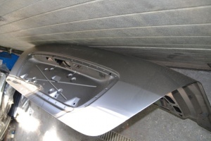
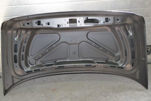
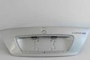
Facelift and pre-facelift trunk lids are the same, except the holes for trunk lid handle and trunk lid covering.
It is possible to mount facelift trunk lid on pre-facelift vehicle and vice versa (assuming trunk lid handle and lid covering is also mounted from the donor vehicle).
 |
 |
 |
 |
Trunk lid covering
There are differences between pre-facelift and facelift vehicles in how trunk lid covering attached to the trunk lid.
Pre-facelift
Pre-facelift vehicles (To Date: 01/09/2002) have lid covering A2207500081 which is attached to the lid with two screws in center tightened from outside and 7 screws tightened from inside.
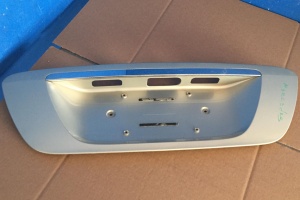 |
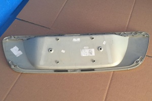 |
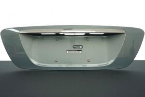
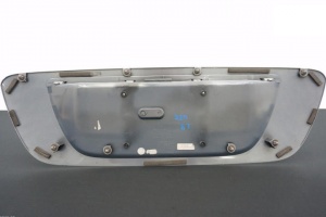
Facelift
Facelift vehicles (From Date: 30/09/2002) have lid covering A2207500281 which is attached to the lid with one bolt in center tightened from inside and 8 retaining clips. The covering has also different trunk lid handle opening.
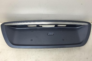 |
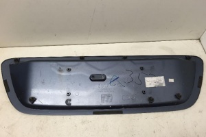 |
 |
The U.S. version A2207500381 has smaller distance between licence plate mounting holes.
 |
 |
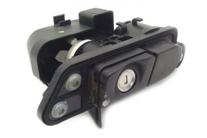
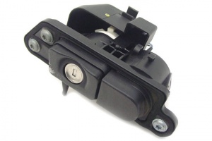
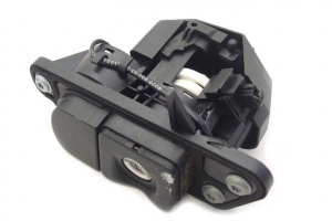
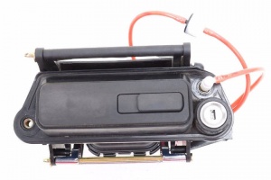
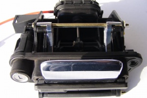
Trunk Lid Handle
| Part No. | Notes |
|---|---|
| A2207500091 | To Date: 30/06/2000 |
| A2207500391 | From Date: 30/06/2000 To Date: 01/09/2002 |
| A2207500893 | From Date: 30/09/2002 To Date: 04/11/2003 |
| A2207501293 | From Date: 04/11/2003 |
 |
 |
 |
 |
 |
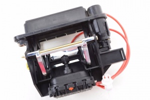 |
For vehicles with option code 889 - KEYLESS-GO:
| Part No. | Notes |
|---|---|
| A2207500291 | To Date: 30/06/2000 |
| A2207500491 | From Date: 30/06/2000 To Date: 01/09/2002 |
| A2207500993 | From Date: 30/09/2002 To Date: 04/11/2003 |
| A2207501393 | From Date: 04/11/2003 |
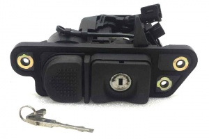 |
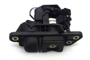 |
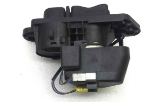 |
 |
 |
 |
For vehicles with option code 881 - REMOTE TRUNK LOCKING:
| Part No. | Notes |
|---|---|
| A2207501093 | From Date: 30/09/2002 To Date: 04/11/2003 |
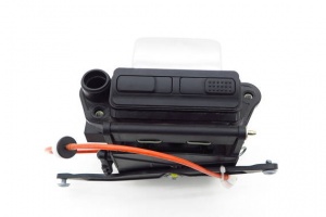
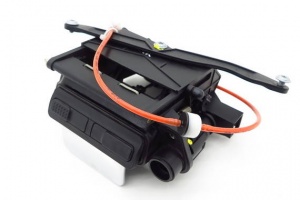
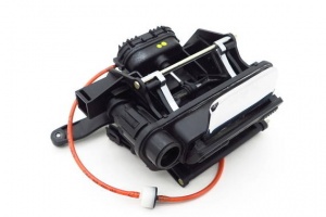
| A2207501493 | From Date: 04/11/2003 |
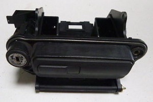
For vehicles with option code 881 - REMOTE TRUNK LOCKING and 889 - KEYLESS-GO:
| Part No. | Notes |
|---|---|
| A2207501193 | From Date: 30/09/2002 To Date: 04/11/2003 |
| A2207501593 | From Date: 04/11/2003 |
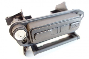 |
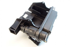 |
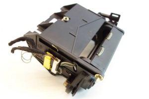 |
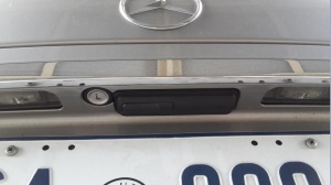
Retractable Trunk Lid Grip
Facelift vehicles without option code 881 - REMOTE TRUNK LOCKING have a hidden handle which appears whenever the trunk lid is opened. The handle is chrome plated and is pneumatically controlled. It is called the Retractable Trunk Lid Grip (RTG).
The Retractable Trunk Lid Grip (RTG) is used to pull down the trunk lid for easy closing. According to M-B the hidden handle was provided to avoid the operator having to touch a wet handle in inclement conditions. STAR DAS refers to it as the "dirt free handle".
 |
 |
 |
Opening trunk
When the trunk lid is opened by either remote control on the key fob, using the driver's door trunk release switch or pressing the switch on the trunk lid, the Pneumatic System Equipment (PSE) Pump applies positive pressure to the latch mechanism which unlocks the latch, releasing the lid which fully opens and also extends the Retractable Trunk Lid Grip (RTG) handle. The RTG stays in the extended position until the trunk is closed.
There should be no hissing sound of air escaping during this operation. If there is a hissing sound for even one to two seconds see the Issues section below.
Closing trunk
When the trunk lid is manually closed by pulling down on the RTG Handle until the latch goes click, the PSE applies positive pressure to the latch mechanism and pulls the lid closed.
Six seconds later the RTG is moved to the retracted position by the PSE pump applying negative pressure to the latch mechanism. Note, if the RTG has a leakage issue and a hissing sound of air escaping can be heard the RTG handle can take much longer (17s has been observed) to retract.
The positive and negative pressures required for the pneumatic functions are obtained from the Pneumatic System Equipment (PSE) Pump and specifically the 'HECK' port.
Locking Mechanism Actuator
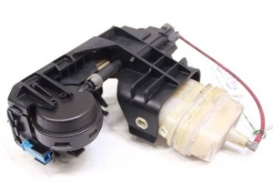
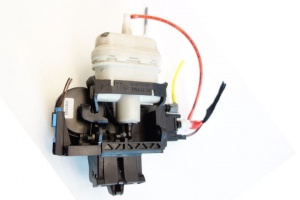
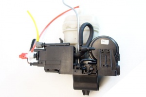
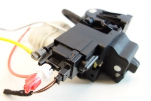
Parts
| Part No. | Notes |
|---|---|
| A2207500584 | To Date: 30/08/2002 |
| A2207500185 | From Date: 30/08/2002 |
 |
 |
 |
 |
 |
 |
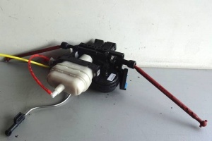
For vehicles with option code 884 - TRUNK LID ADDITIONAL LOCKING MECHANISM (HZS):
| Part No. | Notes |
|---|---|
| A2207500684 | To Date: 30/08/2002 |
| A2207500285 | From Date: 30/08/2002 |
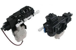 |
 |
 |
Spare parts
These are part numbers of parts that build up the locking mechanism. Unfortunately, some of these parts are not listed in EPC catalog and hence cannot be ordered separately.
- Vacuum solenoid valve (A2308000178)
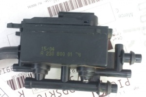 |
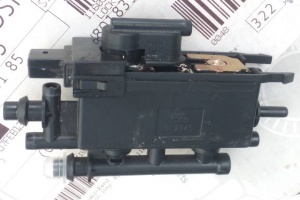 |
- Unlock actuator (A2208000275)
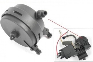 |
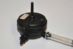 |
- Close & lock actuator (A2208000575 - EUR 52)
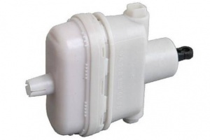 |
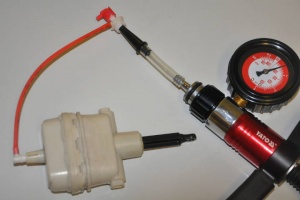 |
- Latch mechanism pre-facelift (A2208000478)
 |
- Clutch (A2028000453)
Function
The Trunk Latch Mechanism has the following functions;
- Switch to detect when the trunk lid is closed. It can be identified by the blue coloured electrical connector (with wires brown, brown/black). The switch is electrically open, i.e., high resistance when the trunk lid is either partially closed (first click) or fully closed. The switch is electrically zero resistance when the trunk lid is open.
- Pneumatic actuator (white) to pull the trunk lid fully closed after the lid is placed manually in the partially closed position.
- Pneumatic actuator (black) which is commonly referred to as a "puck" which releases the latch mechanism to unlock the trunk lid which thus allowing it to open.
- Remote opening of the trunk lid via two solenoid valves which can be identified by the black coloured electrical connector (with wires brown, brown/blue). The solenoid valves are normally unenergised, passing pressure (if any) to the white "close & lock" pneumatic actuator. When a remote open command is given, for example by the button on the remote key fob, +12V is applied to the solenoid valves for 1 second which energises both valves and passes pressure to the black "unlock" pneumatic "puck" actuator which unlocks the trunk lid and allows it to open.
A detailed description of the opening and closing sequences follows: (Reference: HECK function on Pneumatic System Equipment (PSE) Pump).
- When the trunk lid is closed manually to the first position as identified by a loud click, the PSE HECK port provides +ve pressure (27KPa or 4psi) to the trunk lid solenoid valve assembly and hence to the large white actuator which pulls the boot closed tightly, then the PSE HECK port changes to –ve pressure (19”Hg vacuum), which retracts the RTG handle (if installed), then returns the line to atmospheric pressure.
- When the trunk lid is commanded to open either by remote control on the key fob, by pressing the trunk lid button, or by pulling the internal trunk lid release button on the driver's door, the PSE HECK port provides +ve pressure (27KPa or 4psi) to the trunk lid solenoid valve assembly and +12V is applied to the solenoid valves and hence the pressure is passed to the small black actuator which opens the locking latch, thus releasing the lid which fully opens. +ve Pressure is also applied to the RTG Handle, which extends the Handle. After all this is finished the pneumatic line returns to atmospheric pressure.
Closing function
The blue connector connected to latch mechanism is used to determine position of lock. When the lock is open the circuit is closed. When the lock is fully-closed or half-closed, the circuit becomes open. Hence if the blue connector is unplugged the vehicle will consider trunk lid closed.
When the lock reaches half-closed position, the PSE pump will give positive pressure to input line (yellow). Electrically controlled solenoid valve will be off, which will send positive pressure to output port B. This will actuate the white "close & lock" actuator that will push the lock to fully-closed position. Approximately 6 seconds after the lock is fully closed, a negative pressure will be applied to the input line (yellow). If the vehicle is equipped with Retractable Trunk Lid Grip (RTG), the negative pressure (vacuum) will move the handle to the retracted position.
Opening function
When the trunk lid is opened through the SmartKey or push button, the PSE pump will give positive pressure to input line (yellow). Electrically controlled solenoid valve will become energized, which will cause the pressure to be sent to output port C. This will cause the lock to be released and moved to open position.
If the trunk is opened using mechanical key, the trunk release rod connected to trunk latch will release the lock to open position.
The positive and negative pressures required for the pneumatic control of the trunk lid functions are generated by the Pneumatic System Equipment (PSE) Pump.
Hazard Warning Triangle
A common issue with hazard warning triangle is plastic triangle breakage from metal stand.
Broken triangle can be fixed with super glue and cable ties (fixation with cable ties requires drilling small hole in one side of the plastic triangle).
Issues
Common issues relating to the trunk/boot lid functions are:
- Hissing sound on trunk opening or closure can occur due to a leak in either the:
- Retractable Trunk Lid Grip (RTG);
- Trunk latch control solenoid valve module;
- Cracked or broken pneumatic line where it enters the trunk.
- Broken or failed pneumatic actuators.
- Broken wires in pneumatic solenoid valves.
- Cracked or broken pneumatic lines.
- Leakage of water into the trunk because the power closing assist fails to pull the lid closed completely.
- Cannot open the trunk when the battery is dead.
DIY Procedures
Before starting DIY procedures consider to reset the Trunk/Boot CPU by doing the following:
- Remove the 20A yellow fuse from under the rear right passenger seat fuse box.
- Leave it out for about 5 mins.
- Then put it back in and then test the Trunk/Boot functions.
DIY - Removing trunk lid lining
 |
 |
 |
 |
 |
 |
 |
 |
 |
DIY - Removing trunk lining
DIY - Removing trunk locking mechanism actuator
- Remove the trunk lid lining.
- Remove trunk release rod.
- Note that the rod end is placed between one black plastic piece that has screw thread on it and another piece that is like a small latch door.
- Mark the position of the actuator rod with masking tape.
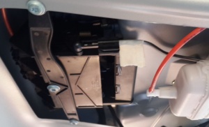
- Caution: It is difficult to remove the actuator rod out of the trunk locking mechanism without breaking the plastic that surrounds it. Be careful as if the rod is not replaced correctly and securely, the trunk can lock and may not be openable with either the key or with the remote.
- The latch door can be opened with a wide flat head screwdriver. Carefully apply a strong steady force.
- Once the latch piece "swings away", the metal rod can be pried out of the plastic piece. The key is to be gentle and patient. It is a good idea to place a spacer behind the rod to hold it in place when applying finger pressure to the plastic tab.
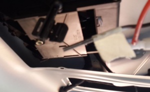
- Once the rod is released the whole actuator can easily be removed from the trunk lid. It is far easier to attempt a repair on a work bench than with the unit still in the car.
- Mark the position of the two Torx screws holding the latch mechanism in place. This makes for easier reinstallation.
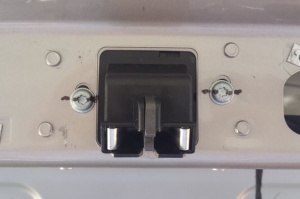
- Remove the two Torx screws and allow the whole actuator assembly to hang down into the trunk.
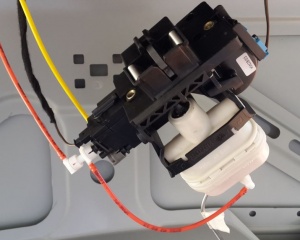
- Note the colours of the pneumatic lines and the position of the black and blue electrical connectors before disconnecting them.
- Re-install in reverse order.
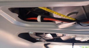
- An annoying rattle can be caused by the RTG one way valve (black and white device in the picture below) rattling against the boot lid. It can be securing firmly with plastic ties.
DIY - Welding trunk lid covering holes
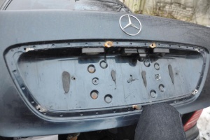
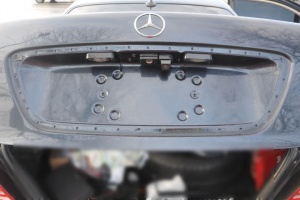
Trunk lid has 7 (pre-facelift) or 8 (facelift) holes which are used to attach the trunk covering (9) to the trunk lid. It is common to see these holes being a source for moisture and rust inside the trunk lid. As an anti-rust measure these holes can be closed by welding. The trunk covering still remains attached to the trunk lid by two central screws (pre-facelift) or one central screw (facelift), although double sided type is recommended to prevent vibration of the covering.
 |
 |
DIY - Repair broken trunk lid actuator pneumatic chambers
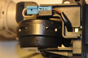
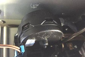
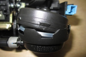
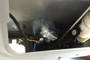
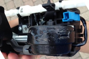
A common problem source is broken air chamber (A2208000275) in the lid latch assembly. It becomes separated and is not able to hold air pressure. This round air chamber is pressurized and depressurized each time the trunk is opened. The two halves are snapped together and the assembly is held together by plastic tabs engaging plastic slots. This is a rather flimsy arrangement for a part that is expected to endure significant pressure cycles.
Note the broken plastic tabs on the perimeter of the actuator.
 |
 |
 |
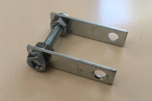
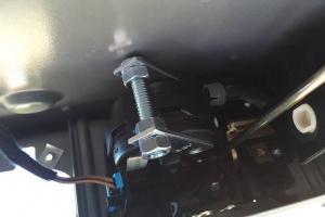
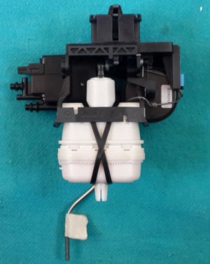
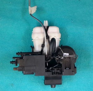
The solution to the problem is to keep the two halves of the plastic air chamber together. The photos below show the repair.
The silicone smeared all over, in a rather ugly way, was applied simply to keep the metal clamp in place. I would have much preferred to use a more elegant repair, one that Mercedes should have considered originally, and that is to use steel spring clips.
 |
 |
 |
 |
 |
Instructions for chamber removal:
- Move the whole assembly to a work bench.
- At the lock mechanism where the rod attaches, take a screw driver or needle nose pliers and gently wedge between rod and plastic slot where the rod attaches.
- Gently pry the rod out of the slot.
- Once the rod is released you can then pull the lock mechanism down so you can access the puck. This isn't hard, but a word of warning! There is a little electrical plug that attaches next to the puck. If you unplug it, make sure your fingers are not next to the lock latch as it will put a death grip on your finger.
- The puck is press fitted into the lock housing and again can be detached by gently prying with a small screwdriver to release.
- Once the puck is detached if the air line is still attached it can be removed if required to bench work the puck. Instead of detaching the airline at the puck just pull the hose off at the attachment point at the puck. It is easy to understand when you get the puck released from the housing.
- Unless you have a replacement puck, then you must attempt to reseal.
- Reseal by compressing the puck then using a two part sealer. Coat the seam around the side of the puck where it was leaking, 360 degrees.
- Let it cure for a few hours.
- Wrap "high speed" tape over the seal.
- Add more tape over the top and bottom to fortify the bond.
DIY - Repair broken hose
A persistent loud hissing noise once you open or close your trunk even for one to two seconds is not normal and usually means that you have a leak in the trunk lock actuator, the RTG actuator, the yellow pneumatic hose or fittings connecting the PSE Pump to the locking mechanism, or the orange pneumatic line or fittings connecting the locking mechanism to the RTG.
It will eventually stop leaking once the leak gets worse. Hopefully the pump will recognise that it is running for too long and will stop working so that it doesn't burn out. Do not leave it in this condition for too long because when the trunk stops sucking down water can get in and ruin your electronic components in the left side of the trunk behind the panels. There is also a possibility of damaging the pump due to constant running.
Often the hissing is caused by a crack in the yellow pneumatic line that is located inside the black braided plastic harness which is easily visible on the inside of the trunk towards the rear window. You can see it when the trunk opens and closes. For whatever reason M-B used a very stiff pipe which cracks easily.
A common mistake is that when you have some aftermarket installation such as a reversing camera, the installer runs their wires alongside the harness, and adhere their wires to this with the additional strain causing premature failure of the stiff pneumatic line.
A simple fix is to use a rubber hose to cover the crack and seal it with adhesive, sealer, tape and plastic ties.
If the hissing is caused by a broken actuator mechanism it is possible to apply a temporary fix by reinforcing the actuators with twitching wire and plastic ties (see other instructions on this page).
But be aware that the forces generated by the PSE Pump are considerable and the best method to achieve a repair is to replace the actuators with new ones.
Second hand actuators will most likely be just as stressed as the broken one you are replacing.
DIY - Repair of trunk lid actuator pneumatic solenoid valves
In the trunk latch mechanism there are two solenoid valves which distribute the pneumatic pressure to the relevant actuator depending on the required result.
A common failure mode is for the control solenoid valve module to crack and leak.
In this example the plugged end of the inlet manifold has cracked. During manufacture a ball bearing was pressed into the manifold to seal it off. With age it has eventually cracked and even though not a large crack, it caused a very loud hissing noise as the air escaped when the trunk lid was opened.
The small crack shown in the example above was easily repaired using super glue and a small hose clamp.
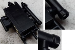 |
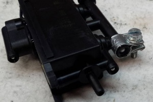 |
DIY - Clean and regrease trunk lid actuator pneumatic solenoid valves
Once the trunk lid pneumatic actuator is removed from the vehicle it can be dismantled on the work bench.
- Valve assembly can be withdrawn from latch mechanism by pressing in the two small plastic tabs. Note there is no mechanical coupling between the control solenoids and the latch mechanism even though it looks like there might be.
- Remove the top front cover over the electrical connector.
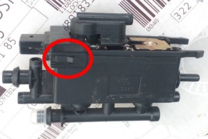
- Then press in two small plastic tabs and remove the top rear cover.
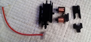
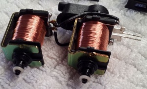
- Before reassembly check the electrical pneumatic solenoid valves.
- Reassemble in the reverse order but apply silicon dielectric or vacuum grease to the pneumatic seals before assembly.
DIY - Check electrical performance of trunk lid pneumatic solenoid valves
The electrical circuit diagram is very simple with the two coils just connected in parallel. A diode is also connected across the coils to reduce current surge when the coils are switched off. (Here is the theory: The magnetic energy stored in energised coils can generate a large spark across the operating switch when it is opened and consequently burn the electrical contacts in the switch. A diode provides a path for this excess energy to dissipate harmlessly.) The downside of having a diode in the circuit is that the electrical contacts are now polarised and correct polarity of any applied test voltage must be observed otherwise the diode will burn out. This just means that the '+' and '-' signs on the next diagram must be observed when applying a 12 Volt DC test voltage.
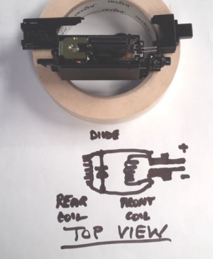
Each valve coil has a resistance of 36 Ohms, therefore the combined resistance for the two coils in parallel as measured across the black electrical connector is 18 Ohms. Note that there is a diode across the coils so that may influence the measurement obtained with some Digital Multi Meters.
After many opening and closing of the trunk the wires between the two pneumatic solenoid valves fatigue and break. They can be easily resoldered once the mechanism is dismantled.
DIY - Check pneumatic performance of trunk lid pneumatic solenoid valves
The first two schematics show the inlet, outlet lines and how they are connected to the control solenoids.
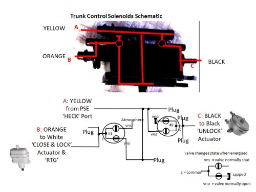
Test 1 is made with the solenoid valves unenergised, which is the normal or static state used to close the trunk.
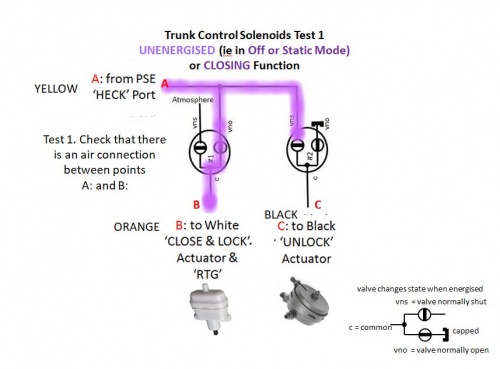
Test 1 Version 2 is easier to follow.
Tests 2 and 3 are made with the solenoid valves energised (polarised 12V), and is the state used to open the trunk.
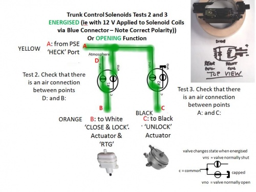
Tests 2 and 3 Version 2 is easier to follow.
DIY - Changing time delay in trunk opening
When the trunk release button is pressed in order to open the trunk there is a time delay before the trunk actually opens. It is possible to change the time delay that occurs using STAR. The default time is 0.25 seconds.
The delay can be changed in DAS under "Control Units"->"Body" -> "PSE - Pneumatic system equipment" -> "Control unit adaptations" -> "Read coding and change if necessary" -> "Trunk lid remote release".
