Airmatic: Difference between revisions
| Line 1,015: | Line 1,015: | ||
==== AIRMATIC VISIT WORKSHOP!==== | ==== AIRMATIC VISIT WORKSHOP!==== | ||
[[File:W220_Warning_Airmatic_Visit_Workshop.jpg|thumb|none|"AIRMATIC VISIT WORKSHOP!" warning on the instrument cluster.]] | {| | ||
|[[File:W220_airmatic_visit_workshop_prefacelift.jpg|thumb|none|"AIRMATIC VISIT WORKSHOP!" warning on the instrument cluster (pre-facelift).]] | |||
|[[File:W220_Warning_Airmatic_Visit_Workshop.jpg|thumb|none|"AIRMATIC VISIT WORKSHOP!" warning on the instrument cluster ([[facelift]]).]] | |||
|} | |||
<!-- WIS GF32.22-P-0003-01B --> | <!-- WIS GF32.22-P-0003-01B --> | ||
| Line 1,028: | Line 1,031: | ||
the vehicle attempts to maintain the set level. | the vehicle attempts to maintain the set level. | ||
Manual and automatic level adjustments are no longer possible. | Manual and automatic level adjustments are no longer possible. | ||
====AIRMATIC STOP, CAR TOO LOW!==== | ====AIRMATIC STOP, CAR TOO LOW!==== | ||
Revision as of 12:17, 30 July 2016
Air Suspension
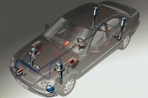
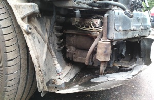
The W220 Airmatic system is a fully supporting air suspension system which provides both static and dynamic support by means of four air bellows or struts located at the wheels. Each strut has an air bag and a dampener built-in the one unit. The struts get air from an air compressor located behind the front bumper close to the front wheel well. On the opposite side is the central reservoir which supplies pressure via pressure lines and a valve unit. The valve unit is connected to a computer which monitors the air pressure, the vehicle weight, the vehicle height requirement and vehicle stance (angle) and then sets the ride height accordingly.
Features
- Level control both manual and speed sensitive.
- Electronic level control which maintains a constant even level at the front and rear axles according to the driving and vehicle load conditions.
- When the vehicle is stationary the level is readjusted if there is a difference of more than +/- 10mm after a door or the trunk lid is opened.
- While driving the level is readjusted if there is a difference of more than +/- 20mm. The level is adjusted to +/- 10 mm every 15 minutes.
- Active Damping System (ADS) which changes the damping forces according to the road conditions and the driver's driving style. The road conditions are determined by vertical acceleration sensors in the body of the vehicle. The horizontal acceleration is determined by measuring the vehicle speed and turn angle.
Advantages
Higher level of driving safety and ride comfort due to:
- Adapting damping to road conditions and driving style.
- Low location of centre of gravity as vehicle lowers above 70KPH.
- Low aerodynamic drag and fuel consumption as vehicle lowers above 70KPH.
- Less tendency for vehicle to lift at speed.
Individual adaptation due to:
- Raising vehicle level for poor road surfaces and when negotiating driveways.
- Two possible damping levels for comfort or sport driving styles in vehicles produced up to 08/99.
- Three possible damping levels for comfort, sport or extreme sport driving styles in vehicles produced after 09/99.
Driver information due to:
- Vehicle level displayed by indicator lamps and switches.
- Warning messages in multi-function display if vehicle is too low.
Function
The functions of the AIRmatic with ADS control module are divided as follows:
- Signal conditioning
- Function logic component
- Safety circuit
Signal conditioning
The following input signals are processed by the function logic component and used for calculations or to provide information:
- Calculation of body vertical acceleration
- Signal from body acceleration sensors
- Calculation of vehicle speed
- Wheel speed signal
- Speed status signal
- Calculation of longitudinal and lateral acceleration
- Wheel speed signal
- Signal from steering angle sensor
- Calculation of compressor control
- Outside temperature, outside air pressure signal
- Reservoir pressure signal
- Vehicle speed signal
- Vehicle level signal
- Duty cycle
- Calculation for valve control
- Level signal from left front axle, right front axle
- Rear axle level signal
- Calculation for control of main reservoir charge valve
- Level signal from left front axle, right front axle
- Rear axle
- Pressure signal
- Calculation of vehicle level
- Signal from level sensors
- Information signals (control)
- Signal from stop lamp switch
- Signal from comfort and sport switch
- Signal from level control switch
- Signal from door contact switch, trunk, remote control
Function logic component
The conditioned input signals are processed in the logic component and converted into output signals.
- Signal from body acceleration sensors (B24/3, B24/8, B24/9):
- The vertical acceleration of the vehicle is calculated using the signals from the body acceleration sensors.
- Front wheel speed signal, left and right:
- Using the wheel speed signal, the ESP control module calculates
- Vehicle speed
- Longitudinal acceleration
- Vehicle status. A distinction is made between a moving and a stationary vehicle. Incorrect wheel speed signals are also detected.
- Steering angle sensor signal (N49):
- The lateral acceleration of the vehicle is calculated using the steering angle sensor signal and the wheel speed signal.
- Signal from level sensors (B22/8, B22/9, B22/3):
- Both front axle level sensors each supply 2 signals. The sensors detect and transfer the distance between the wheel center and the body at both the left and right-hand side of the vehicle.
- The rear axle level sensor supplies 2 signals. The sensor detects and transfers the distance between the wheel center and the body (average calculated from left and right wheel).
- Brake lamp switch signal (S9/1):
- When the driver presses the brake pedal, a signal is received by the ADS logic component and the damping at all wheels is set to "hard". The pitch motion of the vehicle when braking can therefore be reduced.
- Comfort and sport switch signal (N72/1s3):
- The comfort and sport switch signal informs the system about the selection made by the driver between one comfort-oriented and 2 sporty damping maps. The "comfort" setting maintains the damping within the comfortable range as far as the driving style and road conditions will allow. The "Sport 1" setting makes the damping somewhat "harder". The "Sport 2" setting immediately sets the damping force to "hard". The driver's preferred settings are stored until changed by the driver (even with Ignition OFF).
- Signal from level adjustment switch (N72/1s2):
- The control module uses the signals from the level adjustment switch to determine the driver's preferences for the vehicle level:
- Normal level
- Raised level
- The control module uses the signals from the level adjustment switch to determine the driver's preferences for the vehicle level:
- ADS II
- The control module uses the vertical body acceleration, longitudinal and lateral acceleration of the vehicle and the ground speed to determine the optimum level of damping. 4 different damping forces can be set at each wheel by controlling the damping valves located at each wheel. Phased in as of 09/00, the damping is set to the Sport 1 damping level if the vehicle speed is >160 km/h.
- Level control and adjustment
- The control module uses the setting of the level adjustment switch selected by the driver and the ground speed of the vehicle to control the appropriate level control valves and to set the correct vehicle level according to the vehicle load.
- The AIRmatic system is equipped with a pressure reservoir to keep the level control time as short as possible (e.g. after loading). The reservoir pressure is used only when required in order to prevent filling the reservoir too often. This happens, for example if the vehicle level falls below a critical level when loading the vehicle or if the driver has set the vehicle level to "raised level". Pressure from the reservoir is also used when the vehicle is stationary to minimize noise. With normal control when the vehicle is moving, the spring struts are supplied directly by the air compressor.
- Main reservoir pressure control
- The main control parameters are the pressure in the main reservoir, the outside air pressure and the vehicle speed.
- Compressor control
- The compressor is controlled via a relay. Since the compressor is not designed for continuous operation, the absolute running time and cooling phase are monitored to avoid overloading the compressor.
- Wake-up function
A parked vehicle is "woken up" before the engine is started. That is to say, the AIRmatic with ADS control module receives signals from the door contact switches, the trunk switch and infrared remote control indicating that the driver may soon start the engine and drive the vehicle. The current vehicle level is checked immediately and corrected if required. The vehicle level at the front axle is considered to be critical, for instance, if the full wheel angle can no longer be guaranteed. In this case a message appears on the multifunction display in the instrument cluster to warn the driver: "Stop car too low". If the control module is woken (for example by opening one of the doors), there follows a period of spare time before the driver actually starts the engine during which the vehicle level is corrected. This reduces the waiting time required to correct the vehicle level and the vehicle is ready for driving more promptly. Pressure in the main reservoir is used to raise the stationary vehicle. The compressor is only used if the pressure reservoir is empty. It must be ensured that the battery voltage is sufficient to then start the engine.
- Locking function
If the control module detects that all wheels are unloaded when the vehicle is stationary, the valves of the sprint struts are closed. The vehicle therefore remains at the current level. This is essential, for example, when changing a wheel or during repair work (lifting platform).
Safety circuit
The AIRmatic with ADS control module monitors all the important components of the system after they are switched on and during operation. The safety circuit detects faulty signals from sensors, faults in the control module and in the electric line system. If a fault is detected, the system is switched off and a message is displayed on the multifunction display in the instrument cluster to warn the driver. The damper valves for ADS are no longer controlled and remain set to the "hard" damping level (driving safety level). In addition, a fault code is stored in the control module. The level control is partially switched off depending on the fault that occurred. The system always strives to maintain the selected vehicle level. Moreover, the safety circuit continuously monitors the battery voltage. If the voltage falls below 10.5 V or exceeds 17.5 V, the system is switched off until the voltage returns to the specified range.
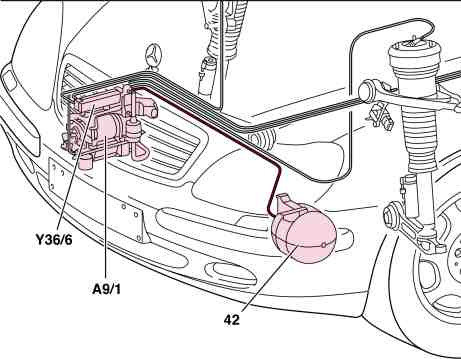
Pressure supply function
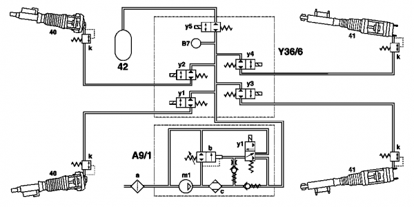
- 42 - AIRmatic central reservoir
- A9/1 - AIRmatic compressor unit
- Y36/6 - Level control valve unit
In normal driving mode, AIRmatic works with a pressure of between 6 and 10 bar (600 and 1,000 KPa or 87 and 145 psi) depending on the load. An electrical compressor is used to supply pressure. This is installed in the AIRmatic compressor unit (A9/1).
In addition the system has an AIRmatic central reservoir (42) which stores the compressed-air. The reservoir pressure is between 13 and 16 bar (1,300 and 1,600 KPa or 189 and 232 psi) (at sea level). The system is either supplied with pressure via the AIRmatic central reservoir or via the air compressor.
Level control function
The AIRmatic at the front and rear axle is a fully supporting suspension system. It keeps the vehicle level constant when the engine is running irrespective of the load. At the same time air from the air compressor is delivered to the spring struts via the valve unit until the vehicle level has been adjusted. The vehicle level at the front axle is recorded by two level sensors at the rear axle and conveyed to the AIRmatic with ADS control module. The level at the individual spring struts is controlled by four level valves in the valve unit and a pressure relief valve on the AIRmatic compressor unit.
An AIRmatic central reservoir for compressed air also enables the vehicle level to be controlled when the engine is not running. In addition the adjustment of the vehicle level is decoupled from the air compressor.
Shut-off position function
If the unloading of all the wheels when the vehicle is stationary is recognized by the control module, the spring strut valves are closed. The vehicle therefore remains at the current level. This is required when changing a wheel or for repair work (hoist) for example.
Normal function (engine running)
When the vehicle is stationary the level is readjusted if there is a difference of more than +/- 10 mm after a door or the trunk lid is opened.
While driving the level is readjusted if there is a difference of more than +/- 20 mm. The level is adjusted to +/- 10 mm every 15 minutes.
Depending on the situation, pressure can be generated by the compressor or the pressure supply of the AIRmatic central reservoir can be used to raise the vehicle. When the vehicle is stationary the pressure from the reservoir is used for noise reasons. Pressure can also be supplied from the compressor and AIRmatic central reservoir at the same time when there is a particularly high pressure demand.
The lowering of the vehicle level is recognized by the control module from the level sensors when loading the vehicle. By actuating solenoid valves air is delivered to the spring struts of the particular front wheel or rear axle until the vehicle has reached its specified value. In addition the pressure relief valve is opened to actuate the respective wheel valve when unloading the vehicle.
Wake-up function (operating period approx. 1 minute)
The AIRmatic with ADS control module is "woken up" using the remote control, door contact switches or trunk illumination switch in order to check the current vehicle level for critical conditions (level too low) and if necessary to raise the vehicle or lower it when unloading. If the vehicle level is lowered by more than 30 mm, it is raised to the normal level by the reservoir (only with a reservoir pressure > 11 bar). At a vehicle level of < -65 mm and even at a reservoir pressure of <11 bar it is raised out of the "critical range" by the compressor to -63 mm (condition: battery voltage > 12.4 V).
If the vehicle level is raised by more than 10 mm when unloading, it is lowered to the normal level by relieving the pressure.
The vehicle cannot be raised by the level control switch.
Function in vehicle condition "Ignition ON"
The same function as for the wake-up function, but without time limit.
Run-on function (operating period approx. 1 minute)
After "ignition OFF" the control module performs changes in the level in order to be able to readjust the vehicle level (raise or lower) during any loading or unloading operations. (The same function as for the wake-up function).
Components
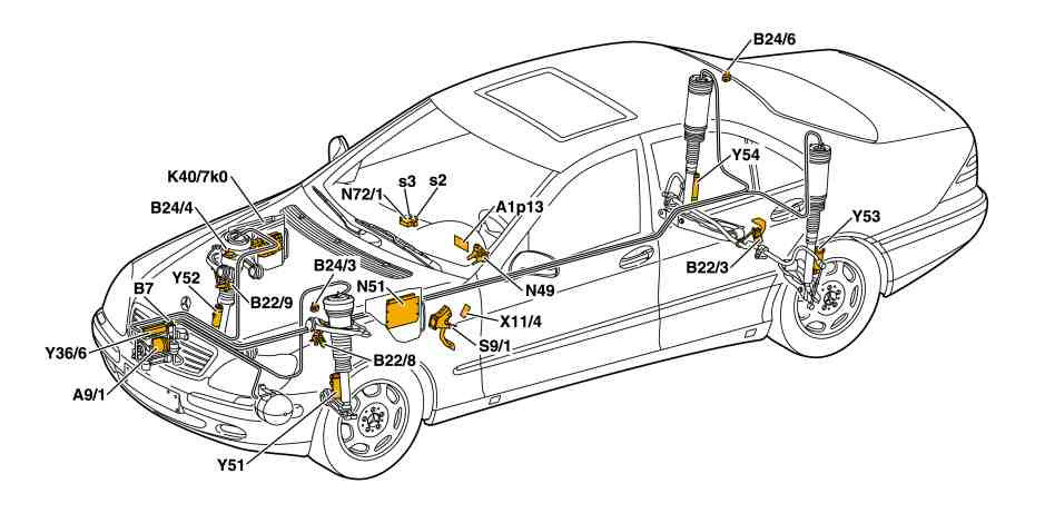
AIRmatic, location of electrical/electronic components:
- A9/1 - AIRmatic compressor unit
- A1p13 - Multifunction display
- B7 - AIRmatic pressure sensor
- B22/3 - Rear axle level sensor
- B22/8 - Left front level sensor
- B22/9 - Right front level sensor
- B24/3 - Left front body acceleration sensor
- B24/4 - Right front body acceleration sensor
- B24/6 - Right rear body acceleration sensor
- K40/7 - Right front fuse and relay module
- kO - AIRmatic compressor relay
- N49 - Steering angle sensor
- N51 - AIRmatic with ADS control module
- N72/1s2 - Level control switch
- N72/1s3 - Comfort and sport switch
- S9/1 - Stop lamp switch
- X11/4 - Data link connector
- Y36/6 - Level control valve unit
- Y51 - Left front axle damping valve unit
- Y52 - Right front axle damping valve unit
- Y53 - Left rear axle damping valve unit
- Y54 - Right rear axle damping valve unit
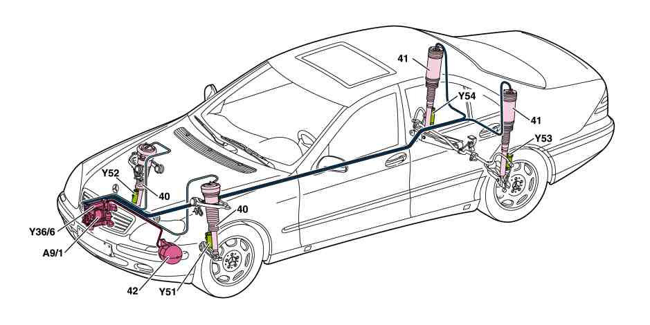
AIRmatic, location of pneumatic/hydraulic components:
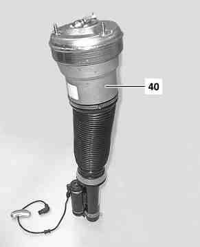
- 40 - Front spring strut
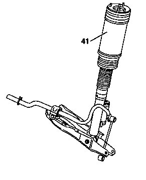
- 41 - Rear spring strut
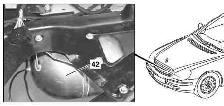
- 42 - AIRmatic central reservoir
- A9/1 - AIRmatic compressor unit
- Y36/6 - Level control valve unit
- Y51 - Left front axle damping valve unit
- Y52 - Right front axle damping valve unit
- Y53 - Left rear axle damping valve unit
- Y54 - Right rear axle damping valve unit
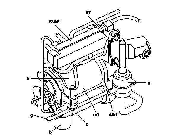
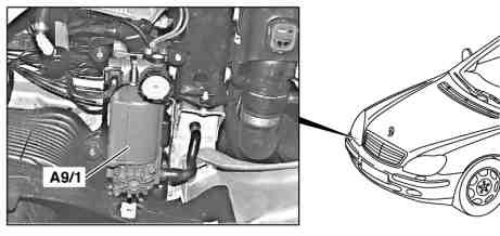
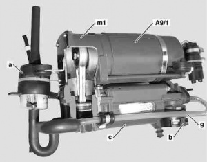
AIRmatic compressor unit (A9/1)
The electric compressor generates the pressure required to lift the vehicle. The pressure relief valve integrated in the compressor unit is used to lower the vehicle.
|
 |
 |
|
Design
|
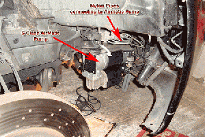
The main part of the AIRmatic compressor unit (A9/1) is the compressor motor (m1). The other parts are the pressure relief valve, overpressure/residual pressure valve (b) and the air drier (c). The air cleaner (a) is located outside the compressor unit. It is connected to the unit by a hose. The air released when the vehicle is lowered is returned to the air filter via the line (g) where it is then guided back out through the filter. The compressor unit is mounted to a mounting plate (h).
The level control valve unit (Y36/6) is fixed at the top of the same mounting plate as the compressor unit and is connected to the compressor by a pressure line. The valve unit is attached to the AIRmatic pressure sensor (B7).
Function
|
|
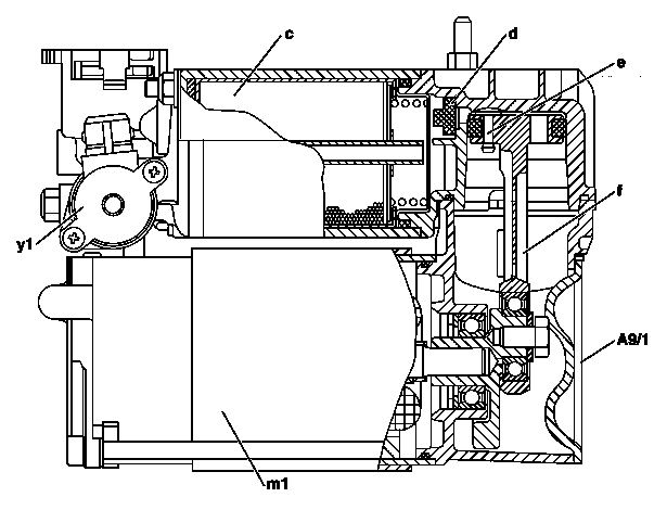
The air compressor is driven by the compressor motor (m1). The air to be compressed is sucked out of the vehicle longitudinal member via an air cleaner and into the chamber underneath the piston. With the downward movement of the piston, the air passes through the inlet valve (e) in the piston crown into the clearance volume. With the upward movement of the piston, the inlet valve closes and the air is compressed. The compressed air is forced on via the outlet valve (d) into the air drier (c).
The silicate filling in the drier removes moisture from the air. From the air drier the dehumidified and compressed air then passes from the air drier into the central reservoir or directly to the suspension struts as required. The pressure relief valve installed in the compressor unit (y1) is required for discharging air when lowering the vehicle. The discharged air is conducted through the air cleaner back into the atmosphere. This also cleans the filter. The air drier is maintenance free. The moisture is delivered back into the air when reducing the pressure.
Air drier (air filter)
It is difficult to get reliable information about the functioning and the scheduled maintenance interval on the air filter. W220 community recommends to replace the air filter time to time to prevent damage of Airmatic compressor. The filter can fill up with debris and salt which may block the filter.
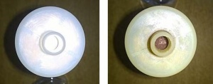
The part number is: A2203200069. Some catalogues list it as "Air Filter, compressor intake."
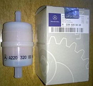
A new air filter costs around EUR 10, and it should not take more than 20 minutes to replace. For replacement instruction see compressor replacement instruction below.
Replacing compressor unit
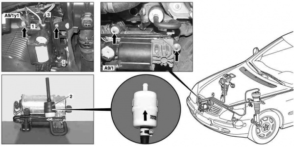
|
|
- Disconnect battery.
- Remove engine compartment paneling (right front part only).
- Unscrew pressure line connection (1) from AIRmatic compressor unit (A9/1).
- Detach connector on AIRmatic pressure reduction valve (A9/1y1).
- Disconnect connector for air compressor motor (3).
- Pull intake hose with air filter (2) out of longitudinal member.
- If the air filter (2) is replaced, the arrow on the air filter (2) must point towards the longitudinal member.
- Unscrew nuts (arrows) and remove AIRmatic compressor unit (A9/1).
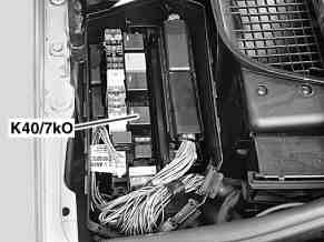
- Detach air compressor relay (K40/7kO). Only when installing a new air compressor. When replacing the air compressor the air compressor relay (K40/7kO) should always be exchanged as the switching contacts may be predamaged.
- Install in the reverse order.
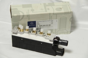
Level control valve unit (Y36/6)
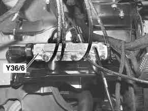
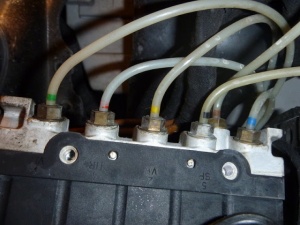
Located on the AIRmatic compressor unit in the right front fender. The valve unit (Y36/6) is the central control unit for the level control, level adjustment and suspension. Supplies the spring struts and central reservoir with compressed-air.
 |
 |
 |
Design
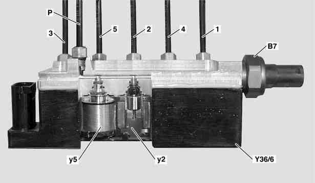
The level control valve unit (Y36/6) is attached to the same retaining plate as the AIRmatic compressor unit (A9/1). It has a solenoid valve for each wheel (y1, y2, y3 and y4) for raising or lowering the vehicle. The AIRmatic central reservoir charge (y5) is also installed in the valve unit. The AIRmatic pressure sensor (B7) is located on the end face of the valve unit.
Function
For reasons of safety only one valve is ever actuated at the same time. If an axle is too low, cycling takes place between the left and right level valve.
Raising the vehicle
The front left, front right, rear left and rear right level valves (y1, y2, y3, y4) are opened as required and the compressed-air stored in the central reservoir or generated by the air compressor motor flows from the level control valve unit (Y36/6) to the individual spring struts. As soon as the required vehicle level is reached at a front wheel, the respective level valve (y1 or y2) closes, the other valve still remains open until the same vehicle level has also been adjusted at the other wheel. At the rear axle both level control valves (y3 and y4) close when the vehicle level averaged between the right and left wheel corresponds to the specified level set by the control module.
Lowering the vehicle
All the wheel level control valves (y1, y2, y3 and y4) are open in the level control valve unit (Y36/6). In addition the AIRmatic pressure release valve (y1) in the AIRmatic compressor unit (A9/1) is open and the compressed-air is reduced via this valve. At the same time the level valves of the individual wheels remain open until the desired vehicle level is reached at each front wheel and at the rear axle.
Inspecting for leaks
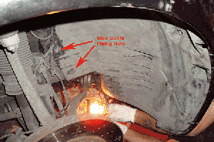
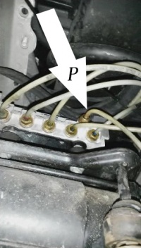
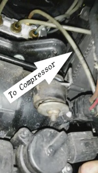
Common failure mode of the level control valve unit is when some valves fail to close thus releasing the air out of system through the P valve or through other valves back to struts. To test whether P valve does not release the air, detach P line (connection to air compressor) and spray it with leak detection spray. After the test use compressed air to clean the valve.
- 1. On the right-hand side of the vehicle remove part of the wheel house inner panel in front fender.
- 2. Spray the pressure line connections 1, 2, 3, 4, 5, P of the level control valve with leak detecting spray. Wait for approx. 10-15 minutes after spraying. This means that minor leaks can be recognized (forming a white cap). Severe leaks are evident immediately.
|

|
|
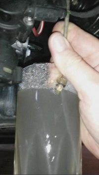
Alternatively, the line can be disconnected from the compressor and tested for leak:
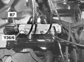
AIRmatic pressure sensor (B7)
Located in the right front fender on the valve unit. Measures the system pressure and used to carry out plausibility checks.
|
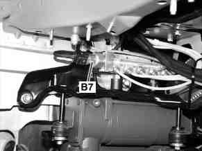
|
Function
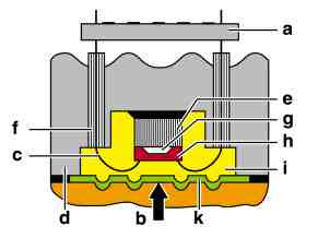
A sensor element compares the fluid pressure (b) to be measured with a reference pressure (g) in the sensor. The pressure (b) is transmitted to the actual sensor element (h) by means of a metal protective diaphragm (k) and a silicone oil layer (i).
An electronics module (a) which supplies the pressure signal in the form of an analog voltage to the control module, is located on the metal housing (d).
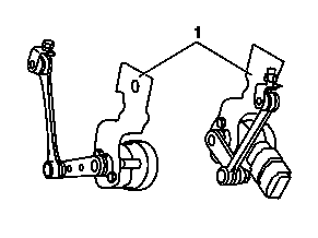
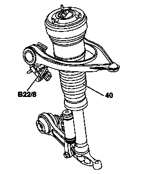
Level sensor (B22/3, B22/8, B22/9)
- B22/3 - Rear axle level sensor
- B22/8 - Left front level sensor
- B22/9 - Right front level sensor
 |
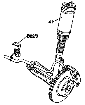 |
Detecting the vehicle level at the front axle and rear axle and supplying the values to the AIRmatic with ADS control module.
Design: 2 Hall sensors in a single housing (redundant design).
Detects vehicle level using link rod from upper transverse control arm at left and right front axle. A sensor at the rear axle monitors the movement of the torsion bar and determines the average vehicle level. Sensor failure is detected by comparing the redundant signals of each sensor.
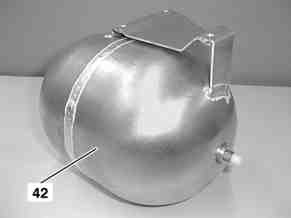
AIRmatic central reservoir (42)
Metal compressed air reservoir. Stores compressed air for level control. Used for decoupling between compressor and level control.
 |
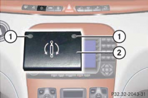
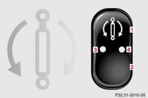
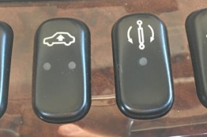
Comfort and sport switch (N72/1s3)
This switch controls Adaptive Damping System (ADS).
The switch with the indicator lamps is located in the upper part of the center console.
 |
 |
 |
The ADS automatically selects the optimum damping for the respective driving conditions. At the same time the suspension is set to either sporty or regular.
The suspension tuning is set according to:
- Your driving style
- Road surface conditions
- Your choice of suspension style, "sport" or "convenience", which you select using the damping switch.
The following suspension styles are available:
- "Convenience" - both indicator lamps (1) are off.
- "Sports 1" - one indicator lamp (1) is on.
- "Sports 2" - both indicator lamps (1) are on (on vehicles produced after 09/99).
The selected suspension style is stored in memory, even after the SmartKey is removed from the starter switch.
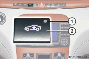
Level control switch (N72/1s2)
 |
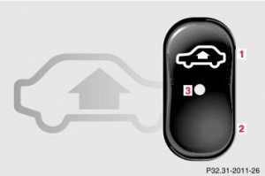 |
This switch controls Airmatic Level control system.
The following vehicle level settings can be selected when the vehicle is stationary:
- "Normal" - for driving on normal roads. The indicator lamp (1) is off.
- "Raised" - for driving on rough roads or with snow chains. The indicator lamp (1) is on.
Select the "Raised" level setting only when required by current driving conditions. Otherwise the fuel consumption may increase and handling may be impaired.
The vehicle chassis ride height is raised or lowered according to the selected level setting and to the vehicle speed (these height adjustments are so small that you may not notice any change):
- With increasing speed, ride height is reduced by up to approximately 3/4 in (20 mm).
- With decreasing speed, the ride height is again raised to the selected vehicle level.
The selected vehicle level setting remains stored in memory even if the engine is turned off and restarted. However, the vehicle lowers to regular level when you exceed a speed of 75 mph (120 km/h) or maintain a speed of between 50 mph (80 km/h) and 75 mph (120 km/h) for more than 5 minutes.
This can be used to raise the vehicle level by 25 mm (20 mm USA). The raised level switch position is indicated by the red indicator lamp (1) in the switch. In addition, the multifunction display in the instrument cluster displays: "AIRMATIC VEHICLE RISING".
As long as the multifunction display in the instrument cluster shows the message: "AIRMATIC VEHICLE RISING", the desired vehicle level has not yet been reached. If the raising of the vehicle is cancelled due to the driving speed, the instrument cluster displays the following message for approx. 10s: "AIRMATIC LEVEL SETTING CANCELLED". If the vehicle is raised several times in quick succession, it may happen that the air compressor shuts down temporarily in order to prevent an overload. The raising sequence will then take an unusually long time.
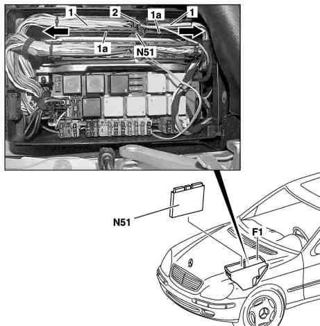
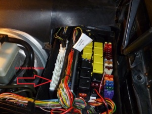
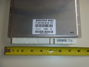
AIRmatic with ADS control module (N51)
AIRmatic with ADS control module, task: To execute all control functions of ADS and AIRmatic. Air suspension control unit is located in left fuse box.
Input Functions
The AIRmatic control module receives input signals over CAN Bus from the following components:
- ESP control module
- Engine control module
- Transmission control module
- Instrument cluster
- Steering angle sensor
- ADS comfort and sport switch
- Level adjustment switch
- Three body accelerometers
- Two front axle level sensors
- One rear axle level sensor
- One Airmatic pressure sensor
Output Functions - Airmatic
The Airmatic input signals are converted in the Airmatic control module to output signals for the following components:
- Four Level control valves
- One main reservoir charge valve
- Four ADS damper valves
- Multi-function display
- Switch indicator lamps
- Air compressor
|
|
AIRmatic compressor relay (K40/7kO)
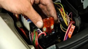
Airmatic compressor relay is located in right fuse box (the first one next to the three 40 amp fuses). The relay starts and stops Airmatic compressor. Faulty relay may fail to stop compressor overheating and damaging it. Hella relays have proven to be reliable. The fuse 32 next to the relay protects the AIRmatic circuit.
 |
 |
Spring strut (40, 41)
The spring strut takes over all the functions of suspension, level control, level adjustment and damping to be carried out.
 |
 |
|
Design
A single-tube gas-filled shock absorber is integrated into the spring strut. The ADS damper valve is attached to the spring strut.
|
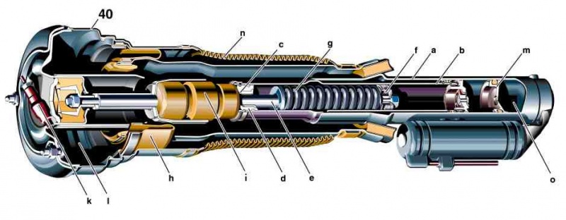
Description - Airmatic Spring Strut Front (40)
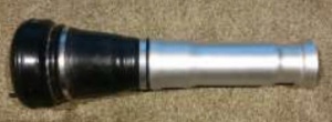
The M-B Airmatic Spring Strut Front (40) consists of three main systems;
- dust cover and protective boot,
- air spring (strut top, residual valve (k), seals, air bellows (h) , strut tube (a)),
- gas pressurized damper or single-tube gas-filled shock absorber.
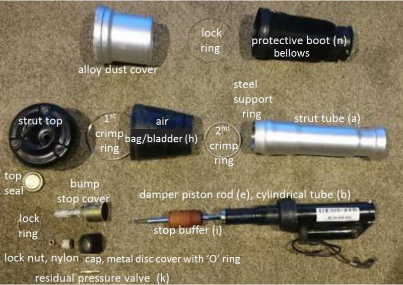
Operation - Airmatic Spring Strut Front (40)
- When filled with air, the rubber air bellows (h) rolls up and down the alloy lower section strut tube (a).
- Without air the rubber air bellows (h) is allowed to kink and crease when depressed and under load would also have the top pressed hard into the inside of the air chamber (l).
- The only sliding action is in the strut damper unit which is oil filled and gas pressurized.
Function
The weight of the vehicle is carried by the compressible air (l) sealed into the air bellows of the spring struts. The rolling hose air bellows (h) is made of rubber. Under dynamic load during driving, the air bellows rolls up parallel with the axis of the spring strut, thus providing the necessary spring travel. The rollup zone on the spring strut is sealed off from the outside by a rubber boot (n) as a protection against dirt.
The vehicle level is raised/lowered by increasing/reducing the air pressure in the air chamber (l), which results in a lengthening/shortening of the spring strut (40). The spring strut incorporates a residual pressure valve (k) which blocks off the pressure chamber in the spring strut in the direction of the supply line in the event of a pressure drop at or below a residual pressure of 4-5 bar.
Replacements
OE
Front (without 4MATIC):
- A2203205113 (replaced by A2203202438)
- A2203202438
Front (4MATIC):
- Left: A2203202138
- Right: A2203202238
Rear:
- A2203205013
- A2203207913 (for option code Z04)
- A2203207813 (for option code Z07) (replaced by A2203202338)
- A2203202338 (for option code Z07)
OE (Bilstein)
Since Bilstein is OEM manufacturer for W220 struts, it is possible to buy OE strut directly from Bilstein much cheaper. It is possible to purchase brand new Bilstein strut for $700.
- Front left (4Matic): 44-051518
- Front right (4Matic): 44-051525
- Front: 44-042295
- Rear: 44-042301
Arnott
Arnott sells both new and remanufactured struts. It is possible to get 10% discount [1] when making order online. Arnott claims [2] that their products use improved air spring bladder exclusively manufactured by Continental which provides longer lifetime than OE. In fact, Arnott provides limited lifetime warranty [3] for their struts.
- Arnott Remanufactured. Arnott remanufactured strut cost $575 but it only has installed new rubber air bladders and not the shock piston seals or gas charge.
In fact, it is possible to buy [4] repair kit allegedly manufactured by Arnott and repair the strut yourself much cheaper (although the press is needed).
- Arnott New.
Arnott new units cost $624. But with all new units you lose the electronic damping. While the new Arnott units allow you to plug in the original wire harness from the car, it simply fools the computer to thinking the selective damping is functioning. In reality it's not and the shock has constant damping setting corresponding to OE "comfort/convenience" setting ("sport 1" and "sport 2" damping settings are not available).
Replacement Tutorials
- http://www.bilsteinus.com/fileadmin/user_upload/user_upload_us/pdfs/E4-WM5-Y328A00_01.pdf (DE/EN)
- http://info.bilsteinus.com/mercedes/ (videos)
Repair options for the front axle air suspension strut
Before replacing a supposed leaky suspension strut, in each case carry out the leak test on the head bearing using soapy water.
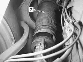
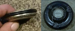
If there is a lack of pressure in the suspension strut it may be that in the full rebound travel condition the air spring plunger separates from the support bearing (picture 1). In this case to test whether there is leakage at the head bearing, proceed as follows:
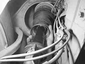
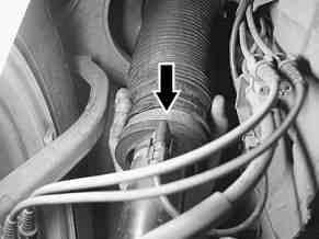
Fill the air spring (using the DAS or other means), in the process pull the air spring plunger of the air spring downwards firmly by hand so that the air does not escape between the air spring plunger and the support bearing (picture 2 and 3). Once the suspension strut is filled, carry out the leak test on the head bearing and repair if necessary.
After using the repair kit likewise proceed as described above when filling the air suspension strut (picture 2 and 3).
Air suspension struts on which the air spring plunger is separated from the support bearing (picture 1) can be filled with air and repaired again without problems. They must not be exchanged for a new suspension strut.
DIY Refurbishment - Airmatic Spring Strut Front
A DIY Refurbishment for a W220 Airmatic Spring Strut Front is shown here. [5]
Tools
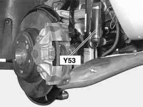
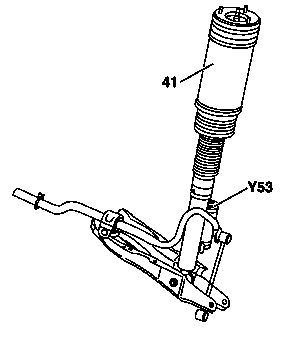
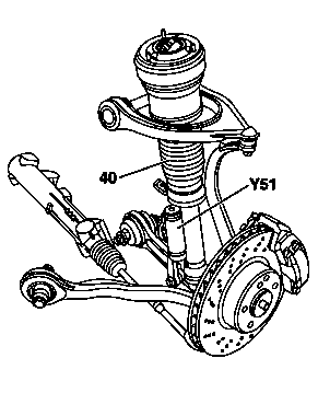
Damping valve unit (Y51, Y52, Y53, Y54)
Damping valve, task: adapts the damping force to the driving style and road condition.
 |
 |
 |
Adaptive damping system (ADS II), function
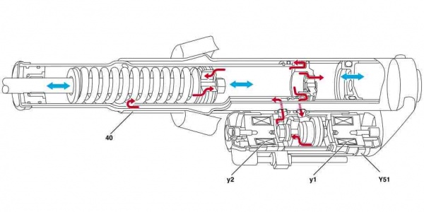
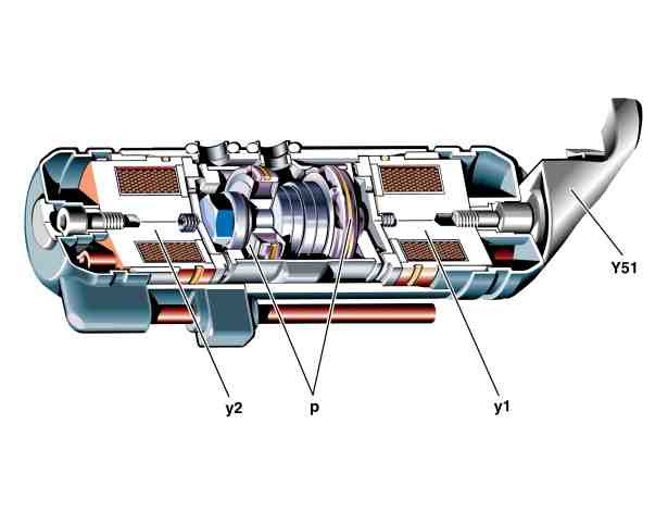
The damping force is regulated in damping valves (Y51, Y52, Y53, Y54). Each wheel has one damping valve installed between the upper and lower chambers of the single-pipe gas-filled shock absorber. Each damping valve contains two electromagnetic valves (y1, y2), allowing four different damping force settings according to how they are actuated via the AIRmatic with ADS control module.
The extremely short adjusting time (milliseconds) means that the optimum damping force setting is available almost immediately if sudden changes in the vehicle level are required, such as during an obstacle-avoidance maneuver.
Design
- Y51 - left front axle damping valve
- y1 - front axle solenoid valve 1
- y2 - front axle solenoid valve 2
- p - piston reed valve pack
The damping valve (Y51, Y52, Y53, Y54) consists of a casing and 2-piston reed valve packs (p). Located above are the spring-loaded solenoid valve pistons and the solenoids. The valve pistons and solenoids form the solenoid valve units (y1, y2).
If the solenoid valve coils (y1, y2) are not actuated, the spring-loaded solenoid valve pistons (y1, y2) keep the holes directly below them closed. Oil is displaced via the reed valve packs (p) and the oil duct located diagonally opposite in the casing.
If the solenoid valve coil (y1) is actuated, for example, the solenoid valve piston (y1) allows the hole to open and the oil can flow over this hole. Only a small amount of oil is displaced via the piston reed valve pack (p). The damping force levels are achieved by means of the differently positioned reed valve packs and controlling the solenoid valves.
Function
The ADS suspension control module is used to achieve four different damping force settings:
- Damping force setting 1
- For comfortable rolling with small sprung mass vibrations and low longitudinal and lateral acceleration. With this damping force setting both solenoid valves y1 and y2 are open so that most of the oil flows parallel to the hard rebound and compression of the operating piston via the softer reed valves at the solenoid valves. The comfort rebound and compression setting is therefore achieved.
- Damping force setting 2
- The reed valves at the valve piston generate a firmer setting. If the vehicle is lowered, solenoid valve y2 is opened and solenoid valve y1 is closed. The reed valves (a = hard compression and b = soft rebound) at solenoid valve y1 generate a hard compression and a soft rebound.
- Damping force setting 3
- The reed valves at the valve piston generate an even firmer setting. If the vehicle is raised, solenoid valve y1 is opened and solenoid valve y2 is closed. The reed valves (c = hard rebound and b = soft compression) at solenoid valve y2 generate a hard rebound and a soft compression.
- Damping force setting 4 (driving safety setting)
- For increased driving safety with high longitudinal and lateral vehicle acceleration. Both solenoid valves y1 and y2 are closed. The reed valves (a = hard compression and c = hard rebound) generate a hard compression and rebound. All the oil flows via the hard rebound and compression of the operating piston. This damping force setting is also selected if the ADS system fails and the ADS suspension warning light (A1e27) comes on in the instrument cluster.
| Damping force setting | Damping valves (Y51-Y54) | Valve control | ||
|---|---|---|---|---|
| Rebound | Compression | Solenoid valve (y1) | Solenoid valve (y2) | |
| 1 | Comfort | Comfort | Open | Open |
| 2 | Soft | Hard | Closed | Open |
| 3 | Hard | Soft | Open | Closed |
| 4 | Hard | Hard | Closed | Closed |
Multifunction display (A1p13)
Various messages concerning the AIRmatic and ADS are shown in the multifunction display in the instrument cluster and in the comfort and sport and level adjustment switches.
AIRMATIC VISIT WORKSHOP!
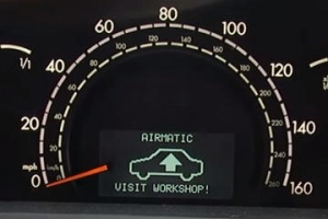 |
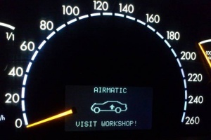 |
In the event of electrical faults in the AIRmatic or ADS system, the following message appears on the multifunction display in the instrument cluster: "AIRMATIC VISIT WORKSHOP!". The fault is stored in the ADS suspension control module and can be read out using the diagnosis tool.
Limp-home function A malfunction in the adaptive damping system causes the ADS to shut down. The suspension is switched to the hardest setting. In the event of a fault in the suspension system or in the level adjustment system, the vehicle attempts to maintain the set level. Manual and automatic level adjustments are no longer possible.
AIRMATIC STOP, CAR TOO LOW!
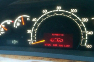
If the vehicle level at the front axle is more than 50 mm (60 mm USA), or at the rear axle more than 60 mm (70 mm USA) below the normal level, the multifunction display in the instrument cluster displays the warning: "AIRMATIC STOP, CAR TOO LOW!". The display disappears again when the level has risen back to 48 mm or 58 mm (58 mm or 68 mm USA) respectively below the normal level.
DIY Repairs
Line Repair
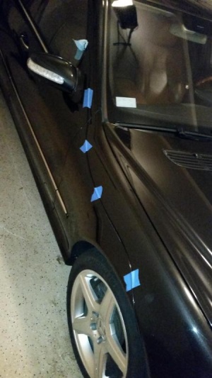
The leak may also develop in any of Airmatic pneumatic lines. The lines to the rear struts go through the interior and it is difficult to find the leak unless the crack is large enough so that the crack can be located thanks to loud hissing sound. Alternative line can be run from front valve block to the rear to test if the line is faulty.
 |
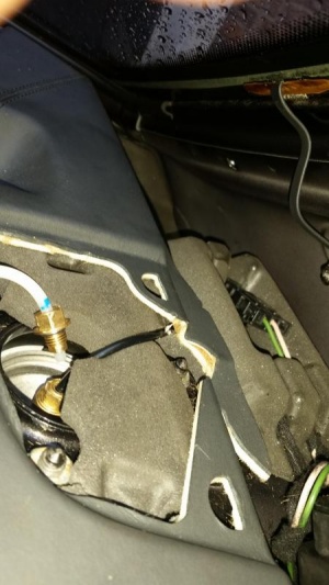 |
Line / Pipe / Hose
MB sells the air line in 5 ft lengths, maximum. From the factory air line is built with continuous length of line with no joins. 5 ft lengths are just for repairs. However, you can buy aftermarket 4mm lines of any length and much cheaper than OEM lines.
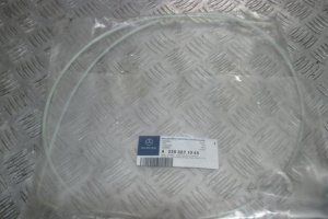
Junction / Connector / Fitting
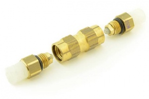
MB sells air line repair connector which can be used to connect air line.
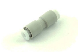
However, there is available cheap, but reliable plastic "push in" connector which can be used to easily connect air lines without any tools.
Set Screw Removal - Airmatic Strut
If you need to loosen the two grub screws which secure the Airmatic strut to the Spring Control Arm for any reason they are particularly difficult to remove. BenzWorld Veteran Member 'mercy-me' has posted a method using heat from a blow torch. [6]
DIY Refurbishment - Airmatic Spring Strut Front (40)
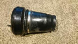
BenzWorld Extremist ‘Pinkster’ purchased a couple of cheap Airmatic struts which were advertised as “leaking returns”. ‘Pinkster’ was able to successfully dismantle and refurbish them. One strut needed the purchase of a new air spring (US$150 on eBay).
Identification of Parts - Airmatic Spring Strut Front (40)
Refer above [7] to identify the part names for the Airmatic Spring Strut Front (40).
Removal - Airmatic Spring Strut Front (40)
- Remove the epoxy and the residual pressure valve (k).
- With the home-made strut top seal tool press the top seal down enough to remove the lock ring.
- Insert a screw or similar device part way into the nylon cover which can then be pulled out.
- Use an air impact driver to undo the lock nut on the top of the damper piston rod (e).
- Remove the complete air spring from the damper unit.
Top Plate Internal View - Airmatic Spring Strut Front
The next Figure shows the inside of the top of the strut.
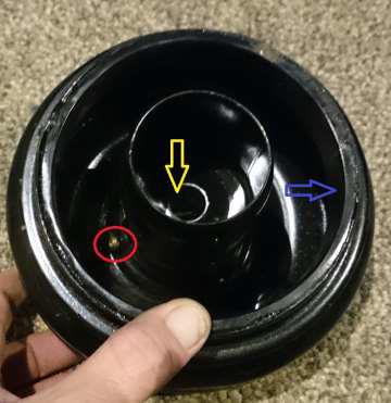
- The yellow arrow points to the hole for the damper piston rod (e).
- The blue arrow points to the inside of the mount for the rubber air bellows (h).
- The red circle shows the brass air inlet to the air spring.
Reinstallation - Airmatic Spring Strut Front (40)
- Fasten the air bellows (h) to the strut top using the 1st crimp ring.
- Install the strut tube (a) into the air bellows (h) and secure with the 2nd crimp ring.
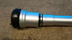
- The next Figure shows the rubber air bellows (h) which is mounted on the outside of the air spring and is held in place by metal crimp rings.

- Notes:
- The bottom end of the lower strut tube (a) is tapered which is for sealing to the damper.
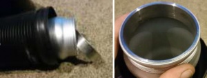
- The Airmatic strut can leak air from the bottom of the lower section if not seated against the rubber of the damper unit correctly.
- If you have a strut leaking from either the top or bottom of the rubber air bellows or a tear in the bellows itself you will most likely need a new air spring assembly. To replace the just the air bellows (h) you will need a hydraulic crimper and most DIYers will not have this tool.
- Check the Seal between the damper and the air spring.
- Install top dust cover.
- Insert the damper into the air spring.
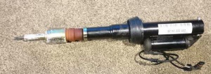
- The next Figure shows a close-up of the strut damper with the bump stop buffer (i) and bump stop cover. The damper is fitted after the air spring has been assembled. It slides through the strut top and has the lower top seal and nut fitted followed by the nylon cover and then the top seal and lock ring. Note the large tapered rubber mount which provides the air spring to damper seal.

- Prepare the strut top plate.
- The next two figures show the top seal in place and the lock ring ready to be fitted using the home-made strut top seal tool.
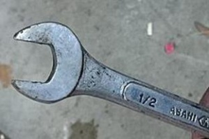
- Final step is to re-install the residual pressure valve (k) using the modified ½” spanner.
Tools Required - DIY Refurbishment Airmatic Spring Strut Front (40)
- Commercial strut top seal tool. For an example see [8]
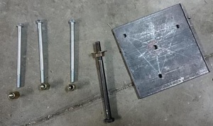
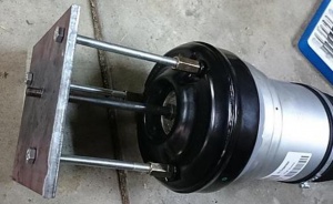
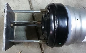
- DIY home-made strut top seal tool. Here is how to make one from a 150mm x 150mm piece of 6mm (1/4") steel plate.
- Accurately mark up the steel plate and drill three 8mm holes to match the pitch circle diameter (pcd) of the strut top plate mounting bolts.
- Drill one 10mm hole in the center.
- Obtain three off 120mm long 8mm bolts for the three 8mm holes.
- Use three 8mm joiner nuts to attach the 8mm bolts to the strut top.
- Obtain one off 150mm long 10mm bolt for the center 10mm hole.
- Thread a nut right to the top of the 10mm bolt and add a flat washer with a little bit of grease.
- Once fitted, tighten the nut to the plate and this will wind down the bolt for removal/replacement of the snap ring and the top seal.
- Impact driver
- DIY modified ½” spanner ground down to fit the air valve.
Emergency Procedure
In case of "AIRMATIC STOP, CAR TOO LOW!" warning on the instrument cluster, the vehicle should be stopped immediately and measures taken.
Possible consequences of riding with leaky strut:
- The compressor will run endlessly which may cause compressor burnout.
- If the front is low, the tire will rub the inner fender.
- There is a risk of damaging other strut on the same axis.
There is a temporary fix for front struts, which can be used to get to the closest workshop:
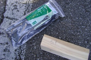 |
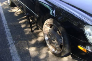 |
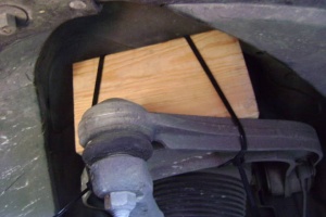 |
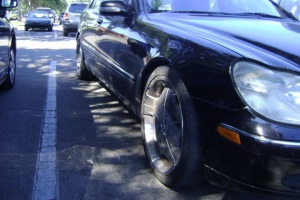 |
The ride will be little bumpy, but not much harsher than it is when pushing the button that stiffens the suspension.
Original limp-home buffers
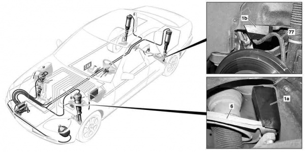
|
|
Front axle
Mount limp-home buffer A2203271230 (1a) onto upper transverse control arm (6). Slowly lower vehicle and make sure that the limp-home buffer makes contact with top of wheelhouse.
Rear axle
Slide limp-home buffer A2203280839 (1b) in between body fold and torsion bar (77). The body fold must lie in the groove of the limp-home buffer. Slowly lower vehicle and make sure that the torsion bar (77) makes contact with the limp-home buffer (1b).
Troubleshooting
"AIRMATIC VISIT WORKSHOP!" message on the instrument cluster

This message is shown in the event of electrical faults in the AIRmatic or ADS system. Use DAS to read error codes.
| Error Code | Description | Probable cause |
|---|---|---|
| C1324-001 | Fault in component Y53y1 (Left rear solenoid valve 1) in assembly Y53 (left rear axle damping valve unit) | Could be caused by faulty solenoid valve in the strut in which case the strut or strut's damping valve unit should be replaced.
If the error code comes in pair with second selenoid valve of the strut then the problem is very likely in the connection. Check the electronic connection between the strut and AIRmatic with ADS control module (N51). |
| C1325-001 | Fault in component Y53y2 (Left rear solenoid valve 2) in assembly Y53 (left rear axle damping valve unit) | See above. |
"AIRMATIC STOP, CAR TOO LOW!" message on the instrument cluster

Note: If the Airmatic leaks substantially it is imperative that it be fixed as soon as possible or else the Airmatic pump may burn out. If the leak cannot be fixed immediately remove the Airmatic compressor relay (K40/7kO) to disable the Airmatic Pump.
Compressor is dead
To test this hypothesis start the car and see if compressor is running (you should hear compressor in the front right fender running). If it is not running check Airmatic fuse and relay (see section above). Faulty relay may cause compressor to run nonstop which will cause compressor to overheat and blow out the fuse.
Strut is leaking
Most common reason for car being too low is a leaking strut. Usually the leak develops in the rubber air below. If the leak is severe, a hissing sound can be heard from the wheel house area. The faulty strut can be located visually by measuring the height. It is very likely that the wheel on the other side (or the wheel on other axle on the same side) will also be brought down significantly, but usually to a bit smaller extent. Note, that the same symptoms can be observed also if the line to the strut is faulty or valve block is faulty (see below), since strut itself has a residual pressure valve which will block air out of strut only in the event of a pressure drop at or below a residual pressure of 4-5 bar, which will not be visually distinguishable from a completely empty strut.
Line to strut is leaking
It is possible that line to the strut develops cracks or microcracks. In case of front struts the line from valve block to strut can be tested with spray test. However, in case of rear struts the line goes from the valve block to rear through interior and thus is not reachable. Simple test is to run an alternative line from the valve block to the strut to check if the original line is faulty (see section on the line repair). If the crack is large it may suffice to push air in the line and locate damaged point by hearing hissing sound.
Valve block is leaking
It is possible that valve block fails to close some valve in which case the pressure will be released back to air compressor and out of the system. Check section above on how to inspect valve block for leaks.
Central reservoir is leaking
To test whether central reservoir can keep pressure DAS can be used which has a pressure test for reservoir. If test shows that reservoir cannot keep the pressure, before replacing it, check with spray test if the line to reservoir is not faulty.
Level sensor is faulty
There are two level sensors for each front wheel and one for the rear axle. If the level sensor reports wrong height the system will think that vehicle already has the required level and will not rise the vehicle. Information reported by level sensors can be viewed using DAS. If the vehicle rises, but then falls down again, the level sensors are likely not the cause.
Vehicle level is too high
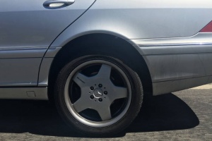
Valve block is leaking
It is possible that valve block fails to close some valve in which case the pressure will be released back to strut rising the car too high. The vehicle is high only while the car is off, since as soon as vehicle is started the computer will try to adjust the level to the programmed level.
Level sensor is faulty
There are two level sensors for each front wheel and one for the rear axle. If the level sensor reports wrong height the system will think that vehicle level is too low and will rise the vehicle above normal height. Information reported by level sensors can be viewed using DAS.
