Aftermarket COMAND replacements: Difference between revisions
(→Circuit Diagram: fixed link) |
Ricebubbles (talk | contribs) m (→DIY Remote Wakeup Circuit: Added modification to wake Erisin on UNLOCK and LOCK commands) |
||
| Line 89: | Line 89: | ||
Note the Erisin ANT/AMP-CON (blue) wire is a source of 12V power to be used to power/control an antenna or an external audio amplifier. It has nothing to do with waking up the Erisin media unit. | Note the Erisin ANT/AMP-CON (blue) wire is a source of 12V power to be used to power/control an antenna or an external audio amplifier. It has nothing to do with waking up the Erisin media unit. | ||
===DIY Remote Wakeup Circuit=== | ===DIY Remote Wakeup Circuit=== | ||
'''Update as of 20200812''' | |||
After designing, building and and installing this circuit, I discovered another issue which annoyed me immensely. Whenever the car was switched off and then returned to within say five to ten minutes, which I seem to do quite regularly, the Erisin would go through the whole startup process again, and I realised I needed to have about an hour delay for [[both]] switch on and switch off. Fortunately my original circuit described below is easily modified to do this, and what's more, is a simpler circuit. With this modification the I/P1 from the PSE SD Valve is not needed nor is the RL1 relay. To achieve this all I had to do was to bypass the RL1 normally open contact with a small piece of wire soldered in place which effectively makes the RL1 relay do nothing at all. (It could be removed completely.) Then to increase the time delay from six minutes to about one hour, just add a 10M Ohm resistor in series with the 1.5M Ohm making a timing resistor of 11.5M Ohms. Now the Erisin powers up the moment the Remote Control UNLOCK or LOCK buttons are pressed, and will stay powered on for about one hour. | |||
'''What follows is the original Description without the above modification.''' | |||
A special DIY Remote Wakeup Circuit has been designed which achieves the required function. It requires an extra connection to the Erisin to wake up the media unit and also requires a small modification to the Pneumatic Systems Equipment (PSE) Pump ECU, plus installation of an additional wire from the boot/trunk to the media unit. | A special DIY Remote Wakeup Circuit has been designed which achieves the required function. It requires an extra connection to the Erisin to wake up the media unit and also requires a small modification to the Pneumatic Systems Equipment (PSE) Pump ECU, plus installation of an additional wire from the boot/trunk to the media unit. | ||
[[File:PSE to Erisin Media Unit Remote Wakeup Block Diagram.JPG|500px|center|thumb|none|PSE to Erisin Media Unit Remote Wakeup Block Diagram]] | [[File:PSE to Erisin Media Unit Remote Wakeup Block Diagram.JPG|500px|center|thumb|none|PSE to Erisin Media Unit Remote Wakeup Block Diagram]] | ||
'''WARNING:''' Be aware the construction of the DIY circuit requires some electronics knowledge, but would make a good project for a beginner. | '''WARNING:''' Be aware the construction of the DIY circuit requires some electronics knowledge, but would make a good project for a beginner. | ||
===How It Works=== | ===How It Works=== | ||
When the key unlock button is pressed to remotely unlock the car, the PSE pump produces a vacuum which is used to unlock the doors and fuel flap. A signal can be obtained from both the PSE SK Valve and the PSE TD Valve to start a timer of approximately five minutes to wake up the Erisin. | When the key unlock button is pressed to remotely unlock the car, the PSE pump produces a vacuum which is used to unlock the doors and fuel flap. A signal can be obtained from both the PSE SK Valve and the PSE TD Valve to start a timer of approximately five minutes to wake up the Erisin. | ||
Latest revision as of 07:08, 12 August 2020
Back to: WIS 82.85 Navigation and Communication System (CNS, ICS, COMAND, FleetBoa) A40/3
Description - Aftermarket COMAND replacements
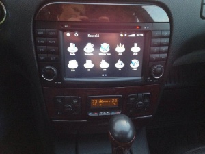
High-end aftermarket car stereo Head Units are available for Mercedes-Benz S-Class W220.
There are several brands available and most offer the following;
- Touch Screen Control
- CD/DVD player (DVD/VCD/HVCD/MP4/MP3/CD/AVI/DIVX et alia).
- Built-in Navigation.
- Blue Tooth to connect mobile phone for hands free use.
- SD Card slot.
- Auxiliary input port for portable multimedia devices (video and audio).
- Reversing Camera option.
- Compatible with original Canbus system for steering wheel control.
Issues - Aftermarket COMAND replacements
Be aware there are several issues related to installing aftermarket head units:
- Steering wheel controls may not work
- Replacement head unit may not work with the original amplifier
Options - Aftermarket COMAND replacements
Alpine INA-W910
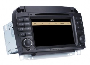
Seicane S018800w
BenzWorld Member Pinkster used a Seicane head unit replacement in a pre-facelift W220, and noted that his car needed the dash modded to fit. See [1]
The Seicane information and installation instructions are here [2]
Erisin
BenzWorld Member Dave2302 used an Erisin head unit replacement with a good description of the ease of installation in a pre-facelift W220 (none Bose Car and no Fibre Optics). See here [3].
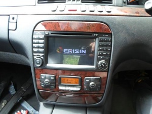
Main installation points discussed were;
- Remove OEM COMAND.
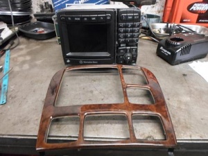
- Remove the CD Changer from the Boot, (Trunk).
- Original Speakers which were plugged to the back of the old COMAND, plug right in to the ERISIN Speakers Plug.
- On the old COMAND Power Plug the Permanent +ve = (thick Yellow / Red), Earth = (Brown) and Antenna Amp / CD Wake Up = (Blue / Black) plugs straight into the Erisin's Power Plug.
- Also on the Erisin's Plug is Red switched +ve wire, and 2 Steering Wheel Button wires. DO NOT CONNECT THESE!! Can Bus takes care of all that and more.
- The Erisin came with two optional use CAN Plugs. Dave2302 note that "There has been waffle all over the Internet and BenzWorld as well as other MB Forums, about splicing into the CAN under the Carpets on the Left Sill, (Rocker Panel), into the HVAC Panel CAN etc etc etc !! The COMAND Communicates with all sorts of other stuff on your Car, so it has CAN Wires going to it, they just aren't that obvious!!"
- There were two plugs with Lever Type catches on the back of the old COMAND, one to the Nav Disc Processor part attached to the COMAND H/U, this has a Blue Lever Catch, and one to the actual COMAND H/U which has a Grey Lever Catch. The "Grey Lever Catch" has the CAN, and one of the Erisin provided adaptors is a Plug with two Wires White & White Black, and two Wires Green & Green Black, which plugs right into the "Grey Catch Plug" on the Car"
- The Green & Green Black wires plug into the CAN Decoder supplied by Erisin and then plug that into the Erisin H/U.
- The Radio Antenna from the old COMAND plugged into the Erisin's Aerial Socket with a simple adaptor.
- The "MUSIC" Icon on the Erisin H/U switches to a SD Card and plays well, nad has a Graphic Equaliser to get it all sounding great. It's crystal clear but too loud at half volume, and every Speaker in the Car works a treat including Parcel Shelf Woofer and Centre Dash Speaker. The sound quality from this unit is far superior to the Old COMAND H/U.
- The look of the Erisin Head Unit completely transforms the look of the Cars interior, it is a true "Update Upgrade"
- Steering Wheel buttons will change Tracks and Radio Stations, and Volume Up and Down.
- The Phone Answer / Hang Up activates the Phone Screen on the H/U.
- Selecting Reverse Gear enables Reverse Camera Screen, but a Camera must be installed.
- Dash Display is yet to be configured.
- An adapter is required to use the Cars Nav Shark Fin Antenna.
Here is Dave2302's method for modding the OEM dash to make the Erisin fit.
- I had to carefully cut the 2 upper COMAND mounting lugs out of the dash, using a Hacksaw blade on it's own, and then carefully also trim the Dash apertures inner edges back (where you can't see this) to get the unit to fit nicely and squarely with an even gap all the way round.
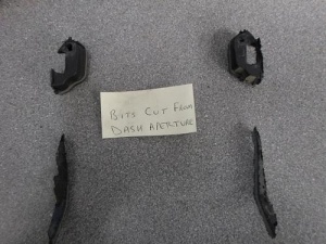
- I have yet to fabricate couple of Upper Mountings to secure it at the top, but have got 4 screws along the bottom lip where the old COMAND has 2 Screws, so next job is to make some nice little brackets to secure the top of it in a decent and secure manner.
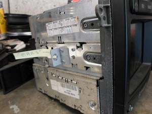
- It is also impossible to use screws on the 2 recessed Centre "Ear Brackets" like the old COMAND has, because the Erisin is a lot wider than the COMAND, but they are resting nicely, and supporting it on the Dash's plastic "Ear Lugs" and I have an idea for that too, which will involve Captive Threaded Studs on the H/U "ears" and trying to get my hand up and put a couple of wing nuts on from behind whilst the Ashtray and A/C Panel is out
- I think that may work, if not instead of threaded studs, I'll make up some tapered locating Dowels and drill the Dash Brackets to suit the taper.
Resources - Aftermarket COMAND replacements
MBWorld has several postings on options and fabulous videos on aftermarket Head Units installed in MB E-class W211 vehicles. See [4]
DIY Erisin Remote Wakeup System
Preliminary
The Erisin ES7882S Media Unit is a favoured after-market COMAND replacement as it “looks the part” perfectly.
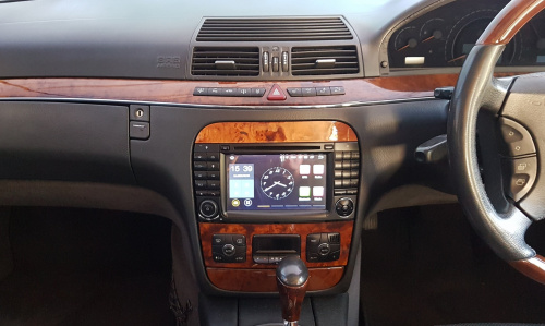
However, it has several annoying features, one of which is the slow boot up. The Erisin ES7882S media unit uses the CAN-Bus signals to wake up and normally no other power connections are required other than +12V and Ground.
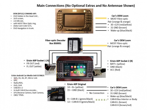
I was extremely disappointed with the slow switch on of the Erisin unit. The device as delivered requires the ignition key to be inserted and turned to position 1 (ACC) or 2 (IGN) before the Erisin would start to boot up after the car has been turned off. It also takes nearly a minute to boot up completely. To overcome this, other enthusiasts have wired the Erisin to be permanently on and to use the in-built sleep function to switch off the screen after a certain time has elapsed. They report that the current draw does not impact significantly on the state of battery charge even after a few days as long as the car is driven regularly. The author’s vehicle tends to sit unused for weeks on end and so any additional drain on a sleeping battery is not desirable, thus ruling out this option. Consequently, the author designed a method to remotely wakeup the Erisin as soon as the car receives an unlock command from the key fob.
Wakeup Options
Ref WIS PE82.85-P-2101-99SH Wiring diagram of cockpit management and data system (COMAND) control module for MODEL 220 as of 1.9.03 with code 352a has a Wakeup wire (bl/sw blae/schwarz blue/black) connected. On the author’s W220 S500L with A40/3 COMAND which has code 527 COMAND DVD APS WITH NAVIGATION, the wakeup blue/black wire sits at +12V until a wakeup signal is generated over the CAN-Bus. The blue/black wire then momentarily pulses towards 0V for about 0.25 secs ONLY when the Ignition is turned from Off to Accessories or to On and initiates the CAN-Bus wakeup. (Note no wakeup signal is produced when the car is unlocked manually or remotely.) The quick negative going pulse is used to wake up the OEM COMAND.
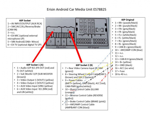
The Erisin ES7882S unit has an ACC red wire as a possible input. If 12V is applied to this red wire the Erisin switches on and stays on as long as the red wire is powered or the ignition is turned on. The ACC is obviously intended for powering and waking up the Erisin using the Accessories (ACC) 12V supply available from the ignition switch. As far as the author can determine for the W220, there is no readily available OEM source of a suitable 12V supply to activate the red wire to wake up the Erisin when it is in sleep mode. Note the Erisin ANT/AMP-CON (blue) wire is a source of 12V power to be used to power/control an antenna or an external audio amplifier. It has nothing to do with waking up the Erisin media unit.
DIY Remote Wakeup Circuit
Update as of 20200812 After designing, building and and installing this circuit, I discovered another issue which annoyed me immensely. Whenever the car was switched off and then returned to within say five to ten minutes, which I seem to do quite regularly, the Erisin would go through the whole startup process again, and I realised I needed to have about an hour delay for both switch on and switch off. Fortunately my original circuit described below is easily modified to do this, and what's more, is a simpler circuit. With this modification the I/P1 from the PSE SD Valve is not needed nor is the RL1 relay. To achieve this all I had to do was to bypass the RL1 normally open contact with a small piece of wire soldered in place which effectively makes the RL1 relay do nothing at all. (It could be removed completely.) Then to increase the time delay from six minutes to about one hour, just add a 10M Ohm resistor in series with the 1.5M Ohm making a timing resistor of 11.5M Ohms. Now the Erisin powers up the moment the Remote Control UNLOCK or LOCK buttons are pressed, and will stay powered on for about one hour.
What follows is the original Description without the above modification. A special DIY Remote Wakeup Circuit has been designed which achieves the required function. It requires an extra connection to the Erisin to wake up the media unit and also requires a small modification to the Pneumatic Systems Equipment (PSE) Pump ECU, plus installation of an additional wire from the boot/trunk to the media unit.
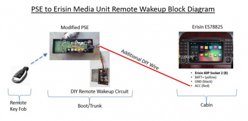
WARNING: Be aware the construction of the DIY circuit requires some electronics knowledge, but would make a good project for a beginner.
How It Works
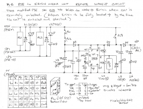
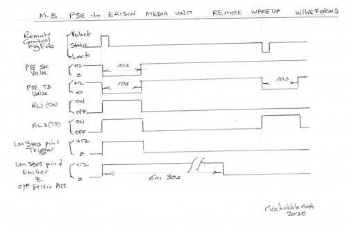
When the key unlock button is pressed to remotely unlock the car, the PSE pump produces a vacuum which is used to unlock the doors and fuel flap. A signal can be obtained from both the PSE SK Valve and the PSE TD Valve to start a timer of approximately five minutes to wake up the Erisin. The SK (Air Inlet Valve) is only activated when the PSE produces a vacuum. The TD (Fuel Flap Lock Valve) is activated during BOTH unlock (vacuum) and lock (+ve pressure) commands. If these two sources are electronically ‘ANDED’ together the only time an output signal is produced is when BOTH valves are activated, which is the unlock situation. Once triggered the timer produces a timed 12V output signal which is connected to the red ACC input wire on the Erisin, thus waking up the media unit for at about six minutes. This gives enough time to open the door, put on the seat belt, insert the key into the ignition and switch to on. By this time the media unit will have booted up and the functions such as reversing camera, navigation app, music app etc will be immediately available. This output 12V signal also latches the DIY circuit on for the duration of the timing period (about six minutes).
Modification to PSE to Access Wakeup Signals (SK and TD Valves)
The PSE Pump and ECU is located in the rear left side of the boot/trunk and is accessible after removing some of the internal linings.
For a thorough description of the W220 PSE Pump see Pneumatic System Equipment (PSE) Pump When the car is locked using the Remote Key, the PSE Pump produces +ve pressure (28Kpa or 4psi), and couples it via the TD port to the Fuel Filler Flap Solenoid which moves a pin out to lock the Fuel Filler Flap, and then returns the port to atmospheric pressure. When the car is unlocked using the Remote Key, the PSE Pump produces -ve pressure (8”Hg vacuum), and couples it via the TD port to the Fuel Filler Flap Solenoid which retracts the pin to unlock the Fuel Filler Flap, and then returns to atmospheric pressure. The following diagram shows the PSE pump producing -ve pressure (vacuum).
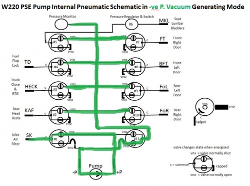
The SK valve is only used when the PSE Pump produces a vacuum. The SK Valve is not activated when the car is locked (when the PSE Pump produces +ve pressure.) Consequently signals from BOTH the SK Valve and the TD Valve are electronically ‘ANDED’ together to produce the required unlock trigger signal for the Timer.
Identifying the PSE Pump Solenoid Valves
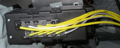
The next diagram shows the PSE ECU removed from its housing with solenoid valves attached. Note it is not necessary to remove the PSE ECU to make the required connections.
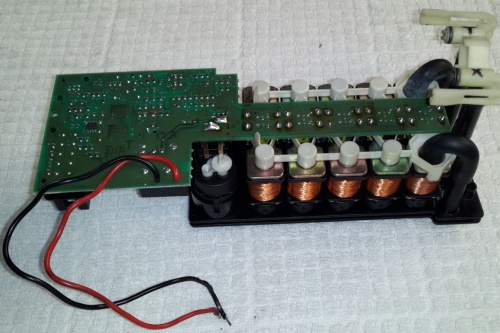
Identifying the PSE Solenoid Valves circuit board connections, each of which has a coil with 34 Ohms resistance.
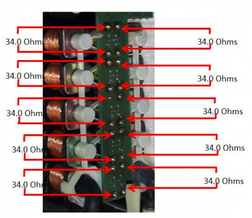
Modification to the PSE Pump ECU
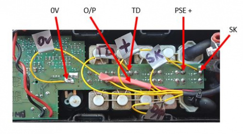
The modification to the PSE that is required is to solder a wire to the SK Valve (control side), solder a wire to the TD Valve (control side), and solder wires to the PSE +ve and the PSE Ground. These wires must be routed externally to the PSE to the DIY Remote Wakeup Circuit by cutting a small slot in the case. (The author was able to use an existing slot in the PSE case for routing the small cable to the new circuit. The author’s PSE pump has been fitted with a copper coil heat exchanger to eliminate excess heat damage to the pump’s internal ports and channels, in the event the PSE pump inadvertently locks on, for some reason. It has already saved one system from permanent damage. See [5] for more details of this modification.)
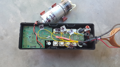
Closeup View of DIY connections with designations.
An additional wire must be installed between the DIY Remote Wakeup Circuit (Output) in the boot/trunk and the Erisin ACC (Red) connection behind the Media Unit in the cabin. (The author found this to be quite easy by using a long plastic rod with the new wire taped to one end, and the rod poked through from the boot to the rear left seat area. The same technique was then used to progressively feed the wire under the carpets down the side of the front left seat, then finally under the front carpet and up into the centre console area.)
Electronic Circuit
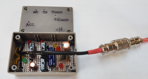
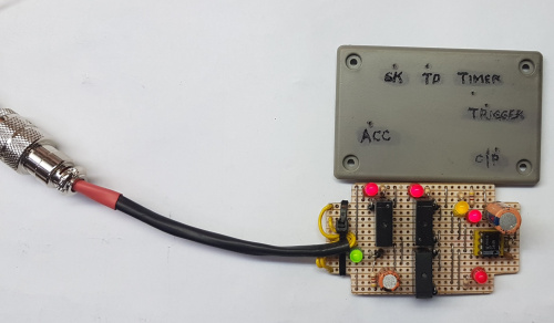
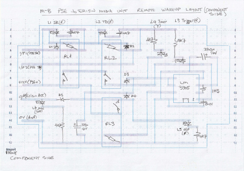
The DIY Remote Wakeup Circuit was constructed on a small piece of electronics proto-typing Veroboard or strip board, which was fitted into a small plastic component box. The completed unit was installed adjacent to the PSE Pump. (The author simply wrapped the box in soft material and squeezed it into a suitable space adjacent to the PSE, and then secured it with plastic ties.) LEDs, although unnecessary, were used extensively in this prototype, so that it was very easy to observe the operation of the completed unit. All up the electronic components cost about $50.
Circuit Diagram
Layout Diagrams
Waveform Diagrams
The waveform diagrams show how the circuit only produces an output (O/P and ACC) signal when BOTH the SK valve and the TD valve are activated. (I.e. an output wakeup command is only produced when the car is unlocked using the remote key fob.)
Bonus
Inspect the table on the circuit diagram which shows the current draw for each possible input and output state. The bonus with this “latching” type of circuit is that there is zero current draw in its off state. Consequently, the addition of this DIY PSE to Erisin Remote Wakeup Circuit does not increase the quiescent current draw from a sleeping battery.
Conclusion
The installation of this DIY remote wakeup for the Erisin media unit in a W220 has significantly enhanced the way the system powers up and makes the whole media unit much more useful during the starting phase. The reversing camera and radio or media player are now available immediately on starting the car and not a minute or so later driving down the road.