Rear axle: Difference between revisions
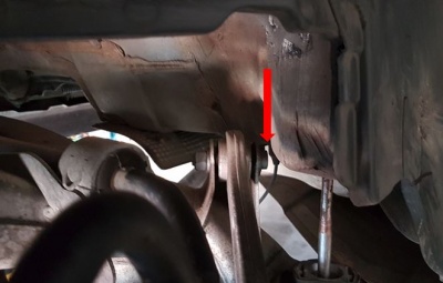
(→Remove/install supporting joint on wheel carrier: added photos) |
|||
| Line 182: | Line 182: | ||
|Control arm bearing, Spring link to rear axle bracket (left and right) | |Control arm bearing, Spring link to rear axle bracket (left and right) | ||
|} | |} | ||
== Remove/install spring control arm and replacement of rubber mount == | |||
<!-- AR35.20-P-0114I, Remove/install spring control arm and replacement of rubber mount, 27.11.08 | |||
MODEL 220.025 /026 /028 /083 /084 /087 /125 /126 /128 /183 /184 /187 | |||
MODEL 220.063 /065 /067 /070 /075 /163 /165 /167 /170 /175 except CODE (487) Active Body Control (ABC) --> | |||
{| | |||
|[[File:W220_remove_install_rear_spring_control_arm_bushings.jpg|500px]] | |||
| | |||
* 6 - Spring control arm | |||
* 6b - Rubber bushing | |||
* 6g - Cover | |||
* 6j - Suspension strut | |||
|} | |||
# Raise vehicle with vehicle lift | |||
# Remove exhaust system at flange connection | |||
# Detach cover (6g) from spring control arm (6). To do this, pull pin out of expansion rivet and remove expansion rivet from cover and spring control arm. | |||
# Remove spring control arm (6) from rear axle carrier. Installation: The rear-axle shaft must be horizontal when tightening the nut. Installation: Tighten bolts or nuts as per tightening angle. | |||
# Remove spring control arm (6) from wheel carrier. Installation: The rear-axle shaft must be horizontal when tightening the nut. | |||
# Remove suspension strut (6j) from spring control arm (6). | |||
=== Remove/install spring control arm rubber mount === | |||
<!-- AR35.20-P-0114-01I, Remove/install spring control arm rubber mount --> | |||
{| | |||
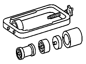
|[[File:W220_W220589014300_removal_and_installation_tool.png|thumb|none|Removal and installation tool W220589014300]] | |||
|[[File:W220_W202589044310_press.png|thumb|none|Press W202589044310]] | |||
|[[File:W220_A2203521365_control_arm_bearing.jpg|thumb|none|Rubber mount A2203521365]] | |||
|} | |||
'''Removing:''' | |||
# Detach exhaust bracket from rear axle carrier. | |||
# Mount sleeve (068b) on bracket (068a). | |||
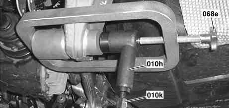
# Position removal and insertion tool using thrust piece (068c) and press (010h) on rear axle carrier. | |||
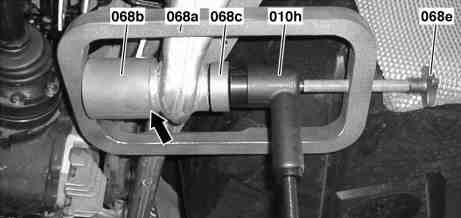
# Fix press (010h) and thrust piece (068c) in position by tightening the hand wheel (068e). Pay attention to the chamfer (arrow) on the sleeve (068b). It must fit exactly against the rear axle carrier. | |||
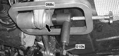
# Press rubber mount part of the way out until the thrust piece (068c) lies against the rear axle carrier (arrow). To do this screw in the pressure screw (010k) of the press (010h). Pushing out the mount prevents the rubber bearing outer race from expanding. If the rubber mount is seized on the bracket (068a), apply a settling blow. | |||
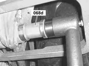
# Insert the thrust piece (068d) and press out the rubber mount. | |||
[[File:W220_remove_spring_control_arm_rubber_mount.jpg|500px]] | |||
[[File:W220_remove_spring_control_arm_rubber_mount_2.jpg|500px]] | |||
[[File:W220_remove_spring_control_arm_rubber_mount_3.jpg|500px]] | |||
[[File:W220_remove_spring_control_arm_rubber_mount_4.jpg|300px]] | |||
'''Removal and insertion tool of the rubber mount:''' | |||
To move out the piston, screw in the pressure screw (010k) of the press (010h) until the piston has moved out completely. | |||
Due to the short stroke of the press (010h) this process must be repeated approx. 5 times. | |||
To do this, the piston is to be moved back by turning back the pressure screw (010k) and simultaneously tightening the hand wheel (068e). The spindle of the hand wheel (068e) must always exert a little pressure onto the press (010h) so that the tools cannot fall out. | |||
'''Install:''' | |||
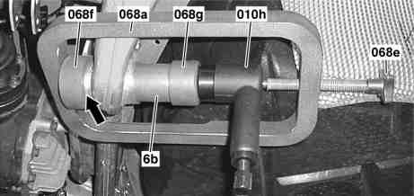
# Replace sleeve (068b) on bracket (068a) by sleeve (068f). | |||
# Insert rubber mount (6b) into hole in rear axle carrier. | |||
# Position removal insertion tool with thrust piece (068g) and press (010h) on rear axle carrier. | |||
# Fix the press (010h) and thrust piece (068g) in position by tightening the hand wheel (068e). Pay attention to the chamfer (arrow) on the sleeve (068f) It must fit exactly against the rear axle carrier. | |||
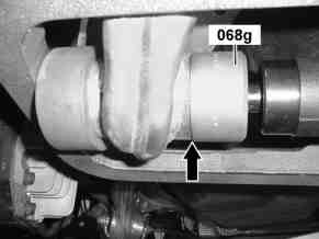
# Press the rubber mount (6b) into the rear axle carrier until the the rear axle carrier (arrow). | |||
# Mount exhaust bracket on rear axle carrier. | |||
[[File:W220_install_spring_control_arm_rubber_mount.jpg|500px]] | |||
[[File:W220_install_spring_control_arm_rubber_mount_2.jpg|300px]] | |||
= Differential = | = Differential = | ||
Revision as of 19:26, 2 September 2021
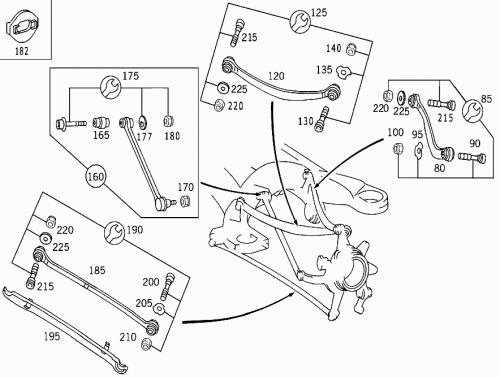
Suspension
|
|
|
Air suspension struts are documented in Airmatic page.
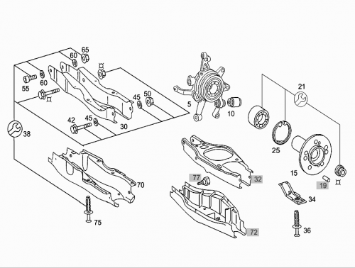
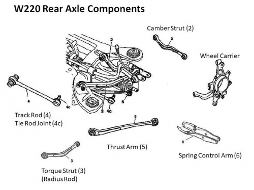
Identifying the components in this diagram with same nomenclature as above:
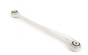
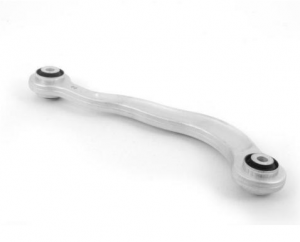
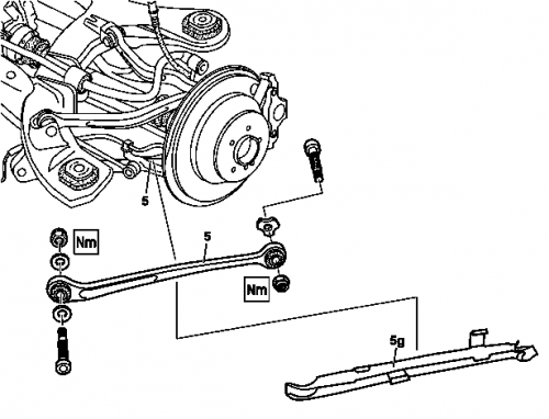
Remove/install thrust arm
|
Shown on model 220 with Airmatic
|
- Raise vehicle
- Unclip thrust arm cover (5g).
- Detach thrust arm (5) from wheel carrier and rear axle carrier. Installation: When tightening the camber strut the vehicle must be relieved of load and on its wheels. Otherwise the rubber mounts are constantly under preload and are damaged as a result.
- Install in the reverse order
Torque specification:
- Self-locking nut, thrust arm to wheel carrier - Stage 1: 45 Nm, Stage 2: 45°
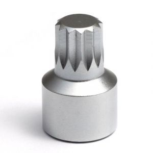
Special tool:
- Screw driver W119589001000 (12mm Triple Square XZN Socket)
Remove/install supporting joint at wheel carrier (wheel carrier installed)
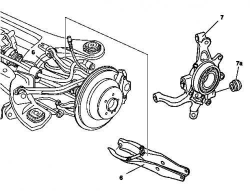
|
Shown on model 220 with Airmatic
|
- Remove rear wheels
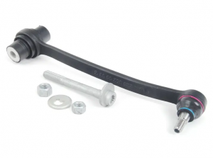
- Remove spring link (6)
- Remove supporting joint (7a) from wheel carrier (7)
- Install in the reverse order
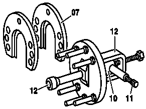
Remove/install supporting joint on wheel carrier
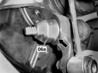
Remove supporting joint:
- Pull supporting joint out of wheel carrier using the extraction and insertion tool.
- Remove extraction and insertion tool with supporting joint.
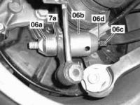
|
Shown on model 220 with AIRMATIC
|
Install supporting joint:
- Fit the extraction and insertion tool with supporting joint to wheel carrier.
- Draw supporting joint into the wheel carrier from behind using the extraction and insertion tool.
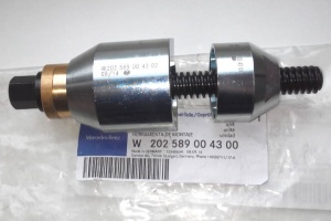 |
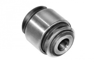 |
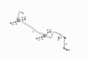
Torsion bar
Subframe
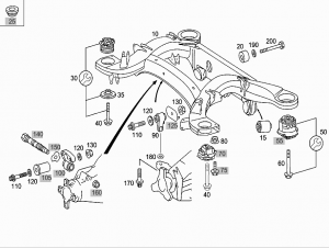
Identifying the components in this diagram with same nomenclature as above:
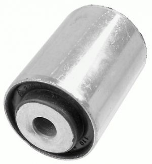
| Part | Part no. | Image | Description |
|---|---|---|---|
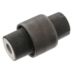
| 15 | A2203521365
LEMFÖRDER 2240201 (EUR 8) |
|
Control arm bearing, Spring link to rear axle bracket (left and right) |
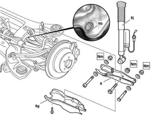
Remove/install spring control arm and replacement of rubber mount
|
|
- Raise vehicle with vehicle lift
- Remove exhaust system at flange connection
- Detach cover (6g) from spring control arm (6). To do this, pull pin out of expansion rivet and remove expansion rivet from cover and spring control arm.
- Remove spring control arm (6) from rear axle carrier. Installation: The rear-axle shaft must be horizontal when tightening the nut. Installation: Tighten bolts or nuts as per tightening angle.
- Remove spring control arm (6) from wheel carrier. Installation: The rear-axle shaft must be horizontal when tightening the nut.
- Remove suspension strut (6j) from spring control arm (6).
Remove/install spring control arm rubber mount
 |
 |
 |
Removing:
- Detach exhaust bracket from rear axle carrier.
- Mount sleeve (068b) on bracket (068a).
- Position removal and insertion tool using thrust piece (068c) and press (010h) on rear axle carrier.
- Fix press (010h) and thrust piece (068c) in position by tightening the hand wheel (068e). Pay attention to the chamfer (arrow) on the sleeve (068b). It must fit exactly against the rear axle carrier.
- Press rubber mount part of the way out until the thrust piece (068c) lies against the rear axle carrier (arrow). To do this screw in the pressure screw (010k) of the press (010h). Pushing out the mount prevents the rubber bearing outer race from expanding. If the rubber mount is seized on the bracket (068a), apply a settling blow.
- Insert the thrust piece (068d) and press out the rubber mount.
Removal and insertion tool of the rubber mount: To move out the piston, screw in the pressure screw (010k) of the press (010h) until the piston has moved out completely. Due to the short stroke of the press (010h) this process must be repeated approx. 5 times. To do this, the piston is to be moved back by turning back the pressure screw (010k) and simultaneously tightening the hand wheel (068e). The spindle of the hand wheel (068e) must always exert a little pressure onto the press (010h) so that the tools cannot fall out.
Install:
- Replace sleeve (068b) on bracket (068a) by sleeve (068f).
- Insert rubber mount (6b) into hole in rear axle carrier.
- Position removal insertion tool with thrust piece (068g) and press (010h) on rear axle carrier.
- Fix the press (010h) and thrust piece (068g) in position by tightening the hand wheel (068e). Pay attention to the chamfer (arrow) on the sleeve (068f) It must fit exactly against the rear axle carrier.
- Press the rubber mount (6b) into the rear axle carrier until the the rear axle carrier (arrow).
- Mount exhaust bracket on rear axle carrier.
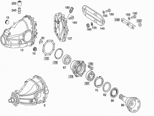
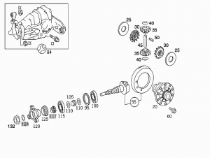
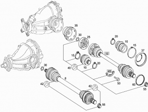
Differential
 |
 |
Shaft
Other
Issues - Rear Drive/Axle Suspension
- Squeaking, creaking noises from the rear axle suspension is a common problem.
- The axlel ball joints that look like bushings lose their internal lubrication.
There is a ball joint at the bottom of each suspension AIRmatic strut and another one at the back of the wheel spider. Four ball joints in total. There is no part number for the bottom strut ball joints but they are the same as the outer ones.
It is recommend to replace both the strut ball joints and the outer ball joints when during replacement.
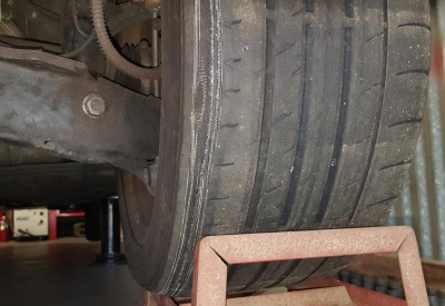
- Unevenly worn tyres that can not be corrected by wheel alignment.
Tools - Rear Suspension
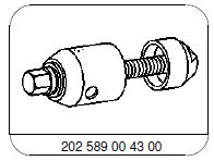
- To remove and replace the bushing a special tool is needed.
- Removal and Installation Tool W202589004300 (see Special Tools page).
DIY Tasks - Rear Suspension
Assessing Wear - Rear Suspension
Use a large shifting spanner (handle 300mm long) to tightly grip each Rear Axle Component in turn. Measure the movement at the end of the spanner handle as force is applied. The results will give an indication of the amount of wear occurring in each axle component.
Typical results for a W220 with 240,000Km;
| Rear Axle Component | Rear Left (RL) Measurements [mm] | Rear Right (RR) Measurements [mm] |
|---|---|---|
| Camber Strut (2) | 15 | 10 -15 |
| Torque Strut (3) | 20 | 30 |
| Track Rod (4) | 15 - 20 | 10 |
| Thrust Arm (5) | 1 -2 | 1 -2 |
| Tie Rod (25) | 0 | 0 |
The conclusion with these results was that the Torque Struts need replacing. Consequently it was decided to replace all possible wear components while the rear end was dismantled. See below for DIY.
Replacing All Worn Components - Rear Suspension
After assessing that the Torque Strut (3) was badly worn and the most likely cause of uneven wear on the inner edge of the rear tyres, the decision was made to replace all components that could wear after 240,000Km life.
All the components in the table above were replaced.
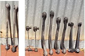
WARNING: Replacing the Torque Strut (3) requires lowering of the complete Rear Suspension Sub-Frame by about 200mm as it is impossible to withdraw the Torque Strut (3) inner bolt without doing so. Consequently before starting make sure to either purchase or manufacture 4 off long bolts which will be used as guide pins to keep the Sub-Frame located whilst it is lowered.
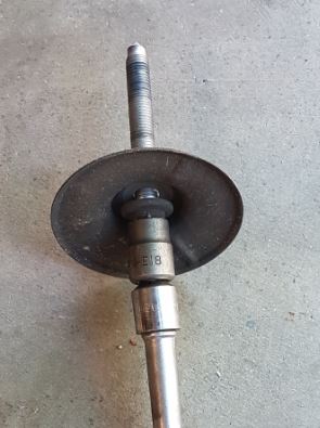
This is one of the original Sub-Frame bolts removed to assess the bolt size, which was M12 x 1,5 x 86.5.
The author found it hard to get M12 x 1.5mm pitch long bolts so manufactured some using existing old stock (bolts from tail shaft refurbishment) welded together to make the required 250mm length.
The next picture shows two of the four guide bolts installed and the Sub-Frame lowered.

Method - Replacing All Worn Rear Suspension Components
- Jack up the vehicle and place on Jack Stands.
- Remove the rear wheels.
- Remove Exhaust Clamps (14mm and 12mm spanners).
- Reomove Exhaust Cross Piece bolt.
- Remove Tail Shaft Safety Cross Piece (4 off bolts 14mm spanner).
- Remove small aluminium Heat Shield (3 off bolts 8mm spanner).
- Remove rear large aluminium Heat Shield (4 off bolts 8mm spanner).
- Apply foot parking brake.
- Remove rear three off Tail Shaft to Differential bolts (E18 and 18mm spanners).
- Mark position of Tail Shaft Centre Bearing Carrier to body with a felt pen. (Makes installation a breeze.)
- Loosen two off bolts Tail Shaft Centre Bearing Carrier (13mm spanner).
- Lower rear end of Tail Shaft.
- Release foot parking brake.
- Release Parking Brake cable slack adjuster (5mm Allen Key).
- Remove Parking Brake cable from centre bracket.
- Remove rear right (RR) brake pad wear sensor (8mm spanner).
- Remove RR disc brake calliper and support with wire (2 off bolts 18mm spanner).
- Remove rear disc holding screw (T7 spanner)
- Remove RR disc.
- Note it is not necessary to remove the rear parking brake shoes.
- Remove RL wheel speed sensor and release from all clips.
- Let the sensor cables hang down.
- Detach Torque Strut (3) from Wheel Carrier (11/16" AF or 18mm spanner)
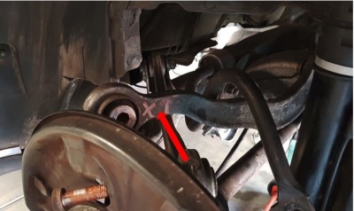
- Mark outer joint of Torque Strut (3) with felt pen with designation Y and arrow pointing up. (Makes installation of new component a breeze.) (Note Torque for installation; M12 bolts 70Nm.)
- Remove Link Rod (25) top and bottom bolts (5/16" AF or 16mm spanner). Note Torque for installation; 40Nm.)
- Remove Camber Strut (2) to Wheel Carrier (Torx and 11/16" AF or 18mm spanner) Note Torque for installation; 45Nm + 45 degrees.)
- Mark Camber Strut (2) outer bush with designation X and arrow pointing up. (Makes installation of new component a breeze.)
- Remove Track Rod Ball Joint (4c) from Wheel Carrier Nut (5/8" AF or 16mm spanner.) Note position of cable bracket on nut side and store on new component.) (Note Torque for installation; 70Nm.)
- Separate Track Rod Ball Joint (4c) from Wheel Carrier using appropriate tool.
- Mark position of Track Rod (4c) offset washers on inner bolt. (If installed in the same position, rear wheel alignment should be maintained.)
- Remove Track Rod (4) inner bolt. (Note Torque for installation; 70Nm.) (Note if required add new 12mm washers to inner end as they had been damaged by wheel aligners.)
- Measure distance between Camber Strut (2) and Torque Strut (3) before undoing inner bolt. This will be used to set the position of the new components. (Note Torque for installation; 70Nm + 120 degrees.) (Approximately 18mm.)
- Repeat above steps for RL side.
- Use a trolley jack placed under the differential to support the Rear Axle Carrier Sub-Frame.
- One at a time,n remove OEM bolts holding axle carrier to car frame and replace with 250mm Guide pins. (Note Torque for installation; Bolt flange 26mm 60Nm + 90 degrees.)
- Pop off ball joint for rear height level sensor to torsion bar bracket.
- Unclip cable near rear height level sensor. Note grommet through floor.
- Cut plastic tie on cable at AIRmatic ride mechanism.
- Unclip cable at 3 places to free up more cable.
- Lower trolley jack keeping Axle Carrier as level as possible until there is access to inner Torque Strut bolt.
- Remove Torque Strut (3) to axle carrier (inner bolt 11/16"AF or 18mm spanner.) (Note Torque for installation; 70Nm + 120 degrees.)
- Remove Camber Strut (2) to axle carrier (inner bolt). (Note Torque for installation; 70Nm.)
- Mark outer edge of Thrust Arm (5) with designation Z and arrow pointing up. (Makes installation of new component a breeze.)
- Mark cover of Thrust Arm (5) as well. (Note hole in cover under rubber bush goes to outside.)
- Remove Thrust Arm (5).
- Adjust level of rear half shaft 1 to 2 degrees above horizontal and torque Thrust Arm (5) to rear axle carrier (inner bolt) (70Nm).
- Torque Thrust ASrm (5) to Wheel Carrier (outer bolt) 45Nm + 45 degrees.)
- Reverse steps above to install remainder of new components. Note do final torquing of accessible bolts with car at correct road height.
- Adjust vehicle road height with Star SDS.
- Get rear wheels aligned.
Rear Shock Absorber - Rubber Lower Bushes
Temporary Fix - Rubber Lower Bushes
A quick temporary fix is to make a slit in the rubber seal and inject some oil.
Full Replacement - Rubber Lower Bushes
Reference: WIS AR32.25-P-1871M Replace rubber mounts of rear shock absorbers
Designations - Rubber Lower Bushes
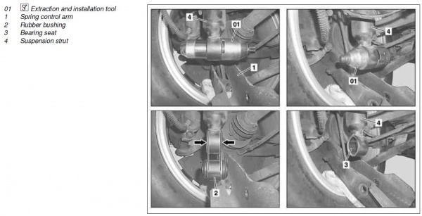
Removal - Rubber Lower Bushes
- Empty suspension strut (4) of rear axle using STAR DIAGNOSIS.
- Partially remove spring control arm (1). TIP: Unhook exhaust system on both rear exhaust-rubber mounts. TIP: Detach spring control arm from rear axle carrier and swing downwards.
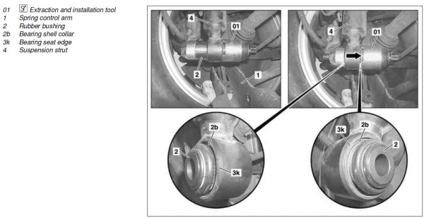
- Remove rubber mounts (2) using extraction and insertion tool (01). AIRmatic Lower Rubber Bushes - Rear Suspension
- Clean and check bearing seat (3).
Installation - Rubber Lower Bushes
- Install rubber mounts (2) using extraction and insertion tool (01). TIP: Do not squeeze plastic parts (large arrow) of the rubber mount (2). Cracked plastic parts result in corrosion and thus to damage to the rubber mount(2).
- Check installation position of the rubber mount (2). TIP: Carry out visual inspection of distances (small arrows) from outer bearing shell collar (2b) to the bearing seat edge (3k). In the event of unequal distances (small arrows) correct the installation position using the extraction and insertion tool (01).
- Install spring control arm (1). TIP:Unhook exhaust system on both rear exhaust-rubber mounts.
- Fill the suspension strut (4) using STAR DIAGNOSIS. TIP: The wheels must not touch the ground while pressurizing because the air spring bellows in the suspension strut (4) will be destroyed if pressurized with the suspension compressed.
- Check AIRmatic for leaks.
Resources - Rear Suspension
http://www.benzworld.org/forums/w210-e-class/1602887-diy-r-r-outer-bushing-rear.html
http://www.benzworld.org/forums/w201-190-class/1673624-worn-out-hub-carrier-bushing-3.html
http://www.benzworld.org/forums/w220-s-class/1623753-loud-creaking-rear-03-w220-4matic.html
http://www.benzworld.org/forums/w220-s-class/1695182-w220-04-s600-abc-issue-squeaking.html
How to change subframe bushes: http://forums.mercedesclub.org.uk/showthread.php?t=90826 and http://forums.mercedesclub.org.uk/showthread.php?t=90827 .
