MOST Television: Difference between revisions
(Created page with "== Analog TV Tuner == Facelift vehicles (starting from 30/09/2003) eqipped with option code 860 have analog TV tuner installed. Part number: A2118200597. {| |...") |
(→MOST + MQS 4-pin connector: fixed fuse number) |
||
| (20 intermediate revisions by 2 users not shown) | |||
| Line 1: | Line 1: | ||
== Analog TV Tuner == | == Analog TV Tuner == | ||
Vehicles starting from 01/09/2003 (except [[Data_Card|option code]] 498 (Japanese) and 494a (USA)) equipped with [[Data_Card|option code]] 860 have analog TV tuner installed. Part number: A2118200597. | |||
The TV tuner is located in the luggage compartment behind the left side paneling. | |||
<!-- WIS AN82.60-P-0001-01A Installing TV tuner in trunk --> | |||
[[File:W220_Installing_TV_tuner_in_trunk.png|none]] | |||
<!-- WIS GF82.60-P-3109CA --> | |||
<!-- [[File:W220_TV_tuner_location_illustrated.png|none]] --> | |||
{| | {| | ||
| Line 7: | Line 15: | ||
|[[File:W220_A2118200597_side.jpg|300px|none]] | |[[File:W220_A2118200597_side.jpg|300px|none]] | ||
|[[File:W220_A2118200597_top.jpg|300px|none]] | |[[File:W220_A2118200597_top.jpg|300px|none]] | ||
|} | |||
===TV function=== | |||
{| | |||
|[[File:W220_MOST_COMAND_Video_menu_with_TV_not_installed.jpg|thumb|none|Video menu in COMAND when TV tuner not installed).]] | |||
|[[File:W220_MOST_COMAND_Video_menu_with_TV_installed.jpg|thumb|none|Video menu in COMAND when TV tuner installed).]] | |||
|} | |||
<!-- WIS GF82.60-P-3109-02CA --> | |||
The TV tuner (MOST) is controlled by the COMAND operating, display and control unit via the Media Oriented System Transport (MOST). In the same way the TV tuner (MOST) receives and processes television programs which have been broadcast in all standards. The audio quality is limited to mono. The TV system operates with a total of 3 reception modules for picture/sound processing. The tuners used cover a reception range of 30 to 866 MHz. The reception range is divided up internally into three bands (VHF low, VHF high and UHF). Each band has its own controllable pre-stage. The TV tuner box has 4 antenna inputs which signals from the car antennae are fed into. The antennae are not allocated to a particular tuner but can be used in the same way by any tuner. The audio antenna diversity operates such that is not influenced by the picture evaluation and vice versa. | |||
====BEST function==== | |||
The TV tuner (MOST) searches the entire TV reception band. In this case, each receivable channel is noted together with its reception field strength. The stations best received (sorted by reception field strength) are stored in the memories of the TV tuner (MOST). | |||
====Videotext function==== | |||
In addition to their television program some stations offer a video text. For this the TV tuner (MOST) is equipped with its own video text decoder. | |||
====AUX function==== | |||
The TV tuner (MOST) has 2 connections for external devices (e.g. video player and DVD player). | |||
====AV function==== | |||
As of 01/09/2002 there are 2 additional video inputs for a video recorder or a video game on the TV tuner. It can only be operated at the playback unit. | |||
====Antenna diversity function==== | |||
The TV tuner (A2/10) analyzes the reception field strength of the incoming TV antenna signals. The high-frequency signal of the antenna with the largest reception field strength is demodulated (antenna diversity). | |||
====Demodulation function==== | |||
The high-frequency signal received is converted into an intermediate frequency (ZF) and separated into audio and video signal parts. The TV picture thus modulated (red-green-blue signal) and the TV sound are passed on to the COMAND and to the operating and display unit rear screen. | |||
====SEEK function==== | |||
The TV tuner (MOST) searches on the reception frequency band for the nearest receivable TV station and demodulates it. | |||
====SCAN function==== | |||
A receivable station is demodulated by the TV-Tuner (MOST) for approx. 8 seconds and displayed. The next receivable channel in the frequency bandwidth is then sought and demodulated, and so on. | |||
===Wiring diagram=== | |||
<!-- WIS pe82.60-p-2220-99sa --> | |||
[[File:W220_A2118200597_connections.jpg|600px]] | |||
[[File:W220_A2118200597_connected.jpg|600px]] | |||
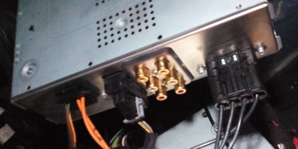
TV tuner has 4 connectors: | |||
# MOST + MQS 4-pin socket | |||
# MQS 18-pin socket | |||
# 2 AV inputs (e.g. for camcorder, DVD player) | |||
# 4 TV antenna inputs | |||
====MOST + MQS 4-pin connector==== | |||
[[File:MOST_MQS_4-pin_connector_TV_tuner.jpg|200px]] | |||
[[File:MOST_MQS_4-pin_connector_diagram.png|200px]] | |||
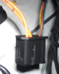
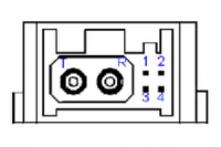
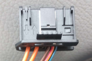
[[MOST]] 2-pin plug (A0025459040) and MQS 4-pin plug (A0025458440) is used inside MOST and MQS 4-pin housing (A0005458430). | |||
MOST housing: | |||
* 1 - MOST in | |||
* 2 - MOST out | |||
MQS 4-pin housing: | |||
* 1 - (brown) - Ground (left wheelhouse in luggage compartment) | |||
* 2 - (red/yellow) - [[fuses|Fuse 61]] in the rear fuse box | |||
* 3 - (blue/black) - MOST wake up | |||
* 4 - unused | |||
====MQS 18-pin connector==== | |||
[[File:A0315457528_TV_Tuner_18-PIN_MQS_plug.jpg|thumb|none|MQS 18-pin plug (A0315457528).]] | |||
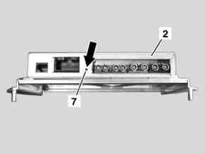
The wires go to operating and display unit display in rear through rear display system intermediate connector. | |||
* 6 (black/white) - rear display system intermediate connector (pin 7) | |||
* 7 (black) - rear display system intermediate connector (pin 3) | |||
* 8 (transparent) - rear display system intermediate connector (pin 1) | |||
* 15 (black) - rear display system intermediate connector (pin 6) | |||
* 17 (brown) - rear display system intermediate connector (pin 2) | |||
* 18 (yellow) - rear display system intermediate connector (pin 4) | |||
* other wires are unused | |||
====AV inputs==== | |||
====4 TV antenna connectors==== | |||
Antennas go to rear window antenna amplifier module. | |||
== Provision For Installation Of Television == | |||
Facelift vehicles equipped with option code [[Option_codes#862_-_PROVISION_FOR_INSTALLATION_OF_TELEVISION|862 - PROVISION FOR INSTALLATION OF TELEVISION]] have wiring in place which allows to easily retrofit TV tuner and rear display system. | |||
{| | |||
|[[File:W220_provision_for_installing_television_wiring_trunk.jpg|thumb|none|Wiring in trunk for connecting TV tuner (antenna, rear display and power connector).]] | |||
|[[File:W220_provision_for_installing_television_wiring_center_console.jpg|thumb|none|Connector in the rear of center console for connecting rear display.]] | |||
|} | |||
{| | |||
|[[File:W220_COMAND-APS_connected.jpg|thumb|none|[[MOST_COMAND-APS|COMAND-APS]] connector with option 862.]] | |||
|[[File:W220_COMAND_MOST_connector.jpg|thumb|none|[[MOST_COMAND-APS|COMMAND-APS]] connector without option 862.]] | |||
|} | |||
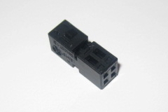
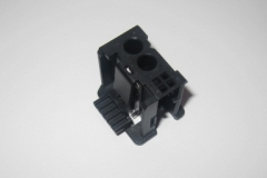
To connect the TV tuner, an additional MOST connector must be added to the MOST loop (see [[MOST]] on how to extend MOST loop with additional device). Then the MOST male connector and MQS 4-pin plug have to be both plugged into A0005458430 housing and the housing plugged into the TV tuner. | |||
{| | |||
|[[File:A0025458440_MQS_4-pin_plug.jpg|thumb|none|A0025458440 MQS 4-pin plug.]] | |||
|[[File:A0005458430_MOST_and_MQS_4-pin_housing.jpg|thumb|none|A0005458430 MOST and MQS 4-pin housing.]] | |||
|} | |} | ||
| Line 32: | Line 145: | ||
|[[File:W220_B67826445_top.jpg|300px|none]] | |[[File:W220_B67826445_top.jpg|300px|none]] | ||
|} | |} | ||
[[File:W220_DVB_Tuner_Teach_in_button.png]] | |||
[[File:W220_DVB_Tuner_remote_control.png]] | |||
== DVB Logic NTG1 Digital TV Tuner == | |||
{| | |||
|[[File:DVB_Logic_NTG1_Digital_TV_Tuner.jpg|thumb|none]] | |||
|[[File:W220_DVB_Logic_TV_tuner_no_image.jpg|thumb|none|DVB Logic TV tuner connected to W220 MOST - no video.]] | |||
|[[File:W211_COMAND-APS_rear.jpg|thumb|W211 (E-Class) COMAND with fakra connector.]] | |||
|} | |||
Sold as digital TV tuner for W220. However, this tuner '''does not''' work with W220 COMAND, since DVB Logic TV tuner for video signal transmission uses a separate fakra connection (available on E-Class COMAND) and not the optical MOST connection. | |||
{{#ev:youtube|https://www.youtube.com/watch?v=hLZ_rfZ3U0o|320|left|DVB Logic DVB-T Digital TV tuner system on Mercedes W220|frame}} | |||
Latest revision as of 13:28, 26 August 2017
Analog TV Tuner
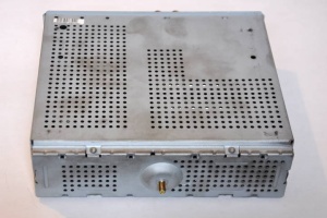
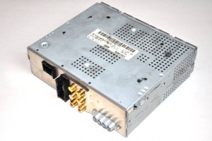
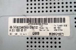
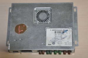
Vehicles starting from 01/09/2003 (except option code 498 (Japanese) and 494a (USA)) equipped with option code 860 have analog TV tuner installed. Part number: A2118200597.
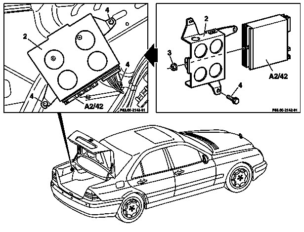
The TV tuner is located in the luggage compartment behind the left side paneling.
 |
 |
 |
 |
TV function
 |
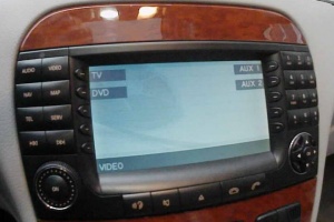 |
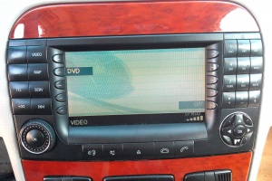
The TV tuner (MOST) is controlled by the COMAND operating, display and control unit via the Media Oriented System Transport (MOST). In the same way the TV tuner (MOST) receives and processes television programs which have been broadcast in all standards. The audio quality is limited to mono. The TV system operates with a total of 3 reception modules for picture/sound processing. The tuners used cover a reception range of 30 to 866 MHz. The reception range is divided up internally into three bands (VHF low, VHF high and UHF). Each band has its own controllable pre-stage. The TV tuner box has 4 antenna inputs which signals from the car antennae are fed into. The antennae are not allocated to a particular tuner but can be used in the same way by any tuner. The audio antenna diversity operates such that is not influenced by the picture evaluation and vice versa.
BEST function
The TV tuner (MOST) searches the entire TV reception band. In this case, each receivable channel is noted together with its reception field strength. The stations best received (sorted by reception field strength) are stored in the memories of the TV tuner (MOST).
Videotext function
In addition to their television program some stations offer a video text. For this the TV tuner (MOST) is equipped with its own video text decoder.
AUX function
The TV tuner (MOST) has 2 connections for external devices (e.g. video player and DVD player).
AV function
As of 01/09/2002 there are 2 additional video inputs for a video recorder or a video game on the TV tuner. It can only be operated at the playback unit.
Antenna diversity function
The TV tuner (A2/10) analyzes the reception field strength of the incoming TV antenna signals. The high-frequency signal of the antenna with the largest reception field strength is demodulated (antenna diversity).
Demodulation function
The high-frequency signal received is converted into an intermediate frequency (ZF) and separated into audio and video signal parts. The TV picture thus modulated (red-green-blue signal) and the TV sound are passed on to the COMAND and to the operating and display unit rear screen.
SEEK function
The TV tuner (MOST) searches on the reception frequency band for the nearest receivable TV station and demodulates it.
SCAN function
A receivable station is demodulated by the TV-Tuner (MOST) for approx. 8 seconds and displayed. The next receivable channel in the frequency bandwidth is then sought and demodulated, and so on.
Wiring diagram
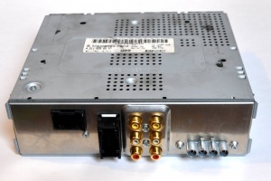
TV tuner has 4 connectors:
- MOST + MQS 4-pin socket
- MQS 18-pin socket
- 2 AV inputs (e.g. for camcorder, DVD player)
- 4 TV antenna inputs
MOST + MQS 4-pin connector
MOST 2-pin plug (A0025459040) and MQS 4-pin plug (A0025458440) is used inside MOST and MQS 4-pin housing (A0005458430).
MOST housing:
- 1 - MOST in
- 2 - MOST out
MQS 4-pin housing:
- 1 - (brown) - Ground (left wheelhouse in luggage compartment)
- 2 - (red/yellow) - Fuse 61 in the rear fuse box
- 3 - (blue/black) - MOST wake up
- 4 - unused
MQS 18-pin connector
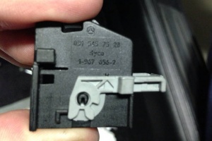
The wires go to operating and display unit display in rear through rear display system intermediate connector.
- 6 (black/white) - rear display system intermediate connector (pin 7)
- 7 (black) - rear display system intermediate connector (pin 3)
- 8 (transparent) - rear display system intermediate connector (pin 1)
- 15 (black) - rear display system intermediate connector (pin 6)
- 17 (brown) - rear display system intermediate connector (pin 2)
- 18 (yellow) - rear display system intermediate connector (pin 4)
- other wires are unused
AV inputs
4 TV antenna connectors
Antennas go to rear window antenna amplifier module.
Provision For Installation Of Television
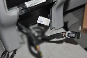
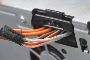
Facelift vehicles equipped with option code 862 - PROVISION FOR INSTALLATION OF TELEVISION have wiring in place which allows to easily retrofit TV tuner and rear display system.
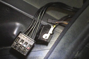 |
 |
 |
 |
To connect the TV tuner, an additional MOST connector must be added to the MOST loop (see MOST on how to extend MOST loop with additional device). Then the MOST male connector and MQS 4-pin plug have to be both plugged into A0005458430 housing and the housing plugged into the TV tuner.
 |
 |
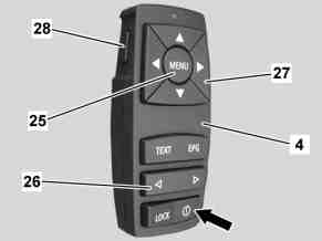
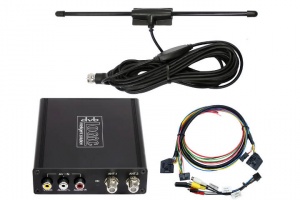
DVB-T Tuner
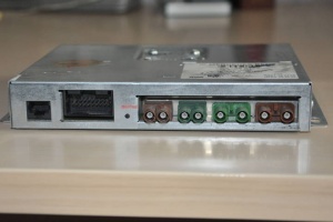
Most European countries have moved from analogue TV broadcasting to digital (see [1]). Fortunately, there is a device called "TV Tuner Digital to Analog" which converts digital signal to analogous and passes it to your analog TV tuner.
| Part number | Note |
|---|---|
| B67826445 | Status: 24.03.2006 |
| B67826455 | Status: 23.05.2006 |
| B67826464 | Status: 13.08.2008 (MB Part A2308700089) |
 |
 |
DVB Logic NTG1 Digital TV Tuner
 |
 |
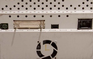 |
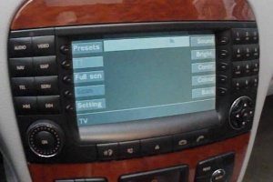
Sold as digital TV tuner for W220. However, this tuner does not work with W220 COMAND, since DVB Logic TV tuner for video signal transmission uses a separate fakra connection (available on E-Class COMAND) and not the optical MOST connection.

