Alternator: Difference between revisions
(→Replacing alternator: added info about M113) |
|||
| (15 intermediate revisions by the same user not shown) | |||
| Line 1: | Line 1: | ||
See a related page of [[battery]]. | |||
==Specification == | ==Specification == | ||
W220 are equipped with two types of alternators. With and without coolant cooling. | W220 are equipped with two types of alternators. With and without coolant cooling. | ||
* S350, S430, S500: 14V/150A | * S350, S430, S500: 14V/150A | ||
** Part no 0986047550 | |||
** AS-PL A0194 (new good quality alternator made in Poland - 137 EUR) | |||
* S55: 14V/180A | * S55: 14V/180A | ||
* S600: 14V/220A | * S600: 14V/220A | ||
| Line 51: | Line 53: | ||
|} | |} | ||
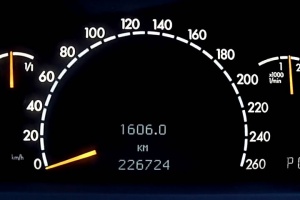
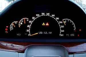
When first opened, the voltage reading will be something like "UB:12.3V". In this example, the 12.3V is the battery voltage with the car at rest with engine off and alternator not charging. | |||
The voltage should be between 11.8V and 12.5V and will typically be 12.3V with a new battery and the car at rest for about 24 hours or more. | |||
{| | |||
|[[File:01 MFD Hidden Menu UB Engine Off.JPG|thumb|none|Voltage reading before starting engine]] | |||
|[[File:06 MFD Hidden Menu UB Engine On.JPG|thumb|none|Voltage reading after starting engine]] | |||
|} | |||
Sometimes the problem can be in the circuit to the [[battery]]. To test whether the [[battery]] actually receives the voltage generated by alternator, use an accurate Digital Volt Meter (DVM) and monitor the alternator output across the [[battery]] terminals. It should match voltage displayed on the instrument cluster. | Start the vehicle. After few seconds the voltage display will disappear. | ||
However, you can locate it again using [[steering wheel]] buttons. | |||
The voltage reading with the vehicle running should be displayed. | |||
Correct voltage measurement on alternator should be around 14V (or 14.5 for a voltage regulator set to 14.5 volts). | |||
The voltage value must not fluctuate (see video of faulty alternator below). | |||
Sometimes the problem can be in the circuit to the [[battery]]. | |||
To test whether the [[battery]] actually receives the voltage generated by alternator, use an accurate Digital Volt Meter (DVM) and monitor the alternator output across the [[battery]] terminals. | |||
It should match voltage displayed on the instrument cluster. | |||
{| | {| | ||
|{{#ev:youtube|https://www.youtube.com/watch?v=FNx5xwkwW3w|320|center|Voltage readings of defective alternator | |{{#ev:youtube|https://www.youtube.com/watch?v=FNx5xwkwW3w|320|center|Voltage readings of a defective alternator|frame}} | ||
|} | |} | ||
'''Note:''' This method is not suitable for testing the voltage of [[battery]], since several consumers activated will cause a non-objective measurement. [[Battery]] voltage must be measured without active consumers (i.e. with minimal load) and only across the [[battery]] terminals. | '''Note:''' This method is not suitable for testing the voltage of [[battery]], since several consumers activated will cause a non-objective measurement. [[Battery]] voltage must be measured without active consumers (i.e. with minimal load) and only across the [[battery]] terminals. | ||
=== Voltage in AC menu === | |||
Alternatively, the voltage can be read out from climate control hidden menu. Switch on ignition, press and hold REST button in climate control until hidden menu appears. Go to value NR.24 for voltage reading. | Alternatively, the voltage can be read out from climate control hidden menu. Switch on ignition, press and hold REST button in climate control until hidden menu appears. Go to value NR.24 for voltage reading. | ||
| Line 72: | Line 88: | ||
# Disconnect negative battery cable. This is important to make sure that when disconnecting alternator battery wire (B+) it does not get shorted to chassis. | # Disconnect negative battery cable. This is important to make sure that when disconnecting alternator battery wire (B+) it does not get shorted to chassis. | ||
# Remove [[serpentine belt]]. | # Remove [[serpentine belt]]. | ||
# Remove oil dipstick to not accidentally | # Remove oil dipstick to not accidentally break it off (important on [[M113]] engine ([[S430]]/[[S500]])). | ||
# Removing alternator bolts. The bolts are Torx 16, but 11mm socket will work fine too. | # Removing alternator bolts. The bolts are Torx 16, but 11mm socket will work fine too. | ||
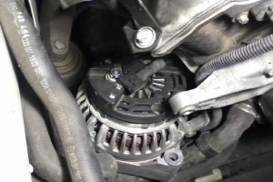
# Tilt alternator out of bracket. Use pry bar if needed (see below). | # Tilt alternator out of the bracket. Use pry bar if needed (see below). | ||
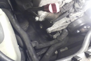
# Rotate alternator pulley down (see photo below) and remove wires. Battery wire needs 13mm socket. The other wire pulls of easily. | # Rotate alternator pulley down (see photo below) and remove wires. Battery wire needs 13mm socket. The other wire pulls of easily. | ||
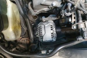
# Remove alternator from the car. S350 | # Remove alternator from the car. On [[M112]] engine cars ([[S350]]) there is a lot of space to do that. On [[M113]] ([[S430]]/[[S500]]) there is less space, therefore removal will involve some difficulties but is possible without removing engine fan (see photo below). | ||
# Reinstall in opposite order | # Reinstall in opposite order. It will be easier to push the alternator in the lower bracket first. To ease installation, metal washers can be pushed (hammered) out of the bolt holes. Note that the coolant bottom hose bracket is attached with the lower bolt. | ||
{| | {| | ||
|[[File:W220_alternator_pry_bar_usage.jpg|thumb|none|Using pry bar to release the alternator from mounting brackets | |[[File:W220_alternator_pry_bar_usage.jpg|thumb|none|Using pry bar to release the alternator from mounting brackets]] | ||
|[[File:W220_alternator_rotated.jpg| | |[[File:W220_alternator_rotated.jpg|thumb|none|Alternator position to remove connectors]] | ||
|[[File:W220_alternator_removed.jpg| | |[[File:W220_alternator_removed.jpg|thumb|none|Alternator removed ([[M112]] engine)]] | ||
|[[File:W220_alternator_removal_angle_M113.jpg|thumb|none|Alternator removal angle (on [[M113]] engine)]] | |||
|} | |} | ||
<!-- http://www.benzworld.org/forums/w220-s-class/1688209-alternator-voltage-regulator-replace-diy.html --> | <!-- http://www.benzworld.org/forums/w220-s-class/1688209-alternator-voltage-regulator-replace-diy.html --> | ||
== Electrical connections == | |||
Alternator is connected with two electrical wires: | |||
* The thick B+ wire is permanently connected to battery's positive terminal through 150A fuse in the front [[fuses|prefuse box X4/10]]. | |||
* The thin blue wire goes to port 15 of right signal acquisition module (SAM). After ignition is switched on 12 volts are supplied from SAM (on S350 only ~1 volt). A small current starts to flow through the line pre-energizing the alternator's field coil. For the alternator to charge, the blue wire must be connected (at least at the beginning to energize it). | |||
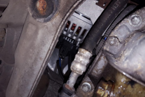
If it is problematic to access the connectors through engine bay, the connectors can be attached by accessing alternator from underneath the car. | |||
[[File:W220_alternator_connections_underneath_car.jpg|thumb|none|Alternator visible from underneath the car]] | |||
==Replacing alternator voltage regulator== | ==Replacing alternator voltage regulator== | ||
| Line 107: | Line 133: | ||
* Bosch: | * Bosch: | ||
** F00M144138 | ** F00M144138 | ||
** F00M144152 | |||
** F00M145247 | ** F00M145247 | ||
** F00M145357 | ** F00M145357 | ||
** F00M145339 | |||
* Transpo: IB247 | * Transpo: IB247 | ||
* Cargo: 235207 | * Cargo: 235207 | ||
| Line 114: | Line 142: | ||
* Mobiletron: VRB247 | * Mobiletron: VRB247 | ||
* HÜCO: 130608 (14.3v) | * HÜCO: 130608 (14.3v) | ||
{| | {| | ||
|[[File: | |[[File:Regulator-bosch-f00m145225-schema.jpg]] | ||
| | | | ||
* B+ - BATTERY - Main battery feed | * B+ - BATTERY - Main battery feed | ||
| Line 125: | Line 150: | ||
* E - Chassis of the vehicle | * E - Chassis of the vehicle | ||
* F - FIELD | * F - FIELD | ||
* L - LAMP - Warning Lamp | * L - LAMP - Warning Lamp (in case of W220 this goes to port 15 of right signal acquisition module) | ||
* DFM - DYNAMO FIELD MODULATION - Duty Cycle signal from the ECU (not connected) | * DFM - DYNAMO FIELD MODULATION - Duty Cycle signal from the ECU (in case of W220 not connected) | ||
|} | |} | ||
L terminal is tapped to a small voltage through the battery light pre-energizing the field coil (when ignition is on). | L terminal is tapped to a small voltage through the battery light pre-energizing the field coil (when ignition is on). | ||
| Line 136: | Line 158: | ||
After the first few revs of the engine a voltage is coming for the alternator side from exciter diodes. This voltage drowns the weak earth through the field coil that was switching the battery light on. Battery light therefore switches of, an indication that the system is charging. | After the first few revs of the engine a voltage is coming for the alternator side from exciter diodes. This voltage drowns the weak earth through the field coil that was switching the battery light on. Battery light therefore switches of, an indication that the system is charging. | ||
In practice L terminal is not connected to physical warning lamp in instrument cluster, but to | In practice L terminal is not connected to physical warning lamp in instrument cluster, but to port 15 of right signal acquisition module (SAM). | ||
Latest revision as of 15:13, 29 July 2025
See a related page of battery.
Specification
W220 are equipped with two types of alternators. With and without coolant cooling.
- S350, S430, S500: 14V/150A
- Part no 0986047550
- AS-PL A0194 (new good quality alternator made in Poland - 137 EUR)
- S55: 14V/180A
- S600: 14V/220A
There are several part numbers compatible to each other.
Faulty Alternator
Symptoms
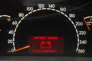
A faulty alternator will fail to charge battery and in a very extreme cases will cause a warning message "BATTERY CHARGE VISIT WORKSHOP!" to be displayed in dashboard.
 |
Typical symptoms are:
- Charging voltage across battery terminal with engine running below about 13.8V.
- Alternator output voltage greater than about 15V. A good fully charged battery should be about 14V across the battery terminals.
- A sudden sound of the alternator (high frequency whine) disappearance.
The car control units have protection against overcurrent. In case of alternator voltage regulator failure, instrument cluster may go dark and cicking sounds may be heard from the doors caused by car unlocking itself for safety purposes.
Causes
An alternator can fail or perform poorly due to:
- Bearings worn or noisy
- Voltage regulator electronic component failure
- Brushes worn
- Cable fracture
- Full wave bridge diode open or short circuit
- Stator winding open or short circuit
- Rotor winding open or short circuit
- Serpentine belt issues
The W220 has very good in-built electronic checking systems and so you should be alerted to the usual failure mechanisms by the car itself. With some electronic capability and the right tools it is easy to diagnose most alternator electrical issues. Mechanical problems are usually diagnosed by hearing unusual sounds from the alternator.
Checking Alternator Voltage
Follow the steps below to obtain the alternator voltage readings via the instrument cluster hidden menu.
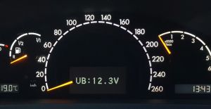
When first opened, the voltage reading will be something like "UB:12.3V". In this example, the 12.3V is the battery voltage with the car at rest with engine off and alternator not charging. The voltage should be between 11.8V and 12.5V and will typically be 12.3V with a new battery and the car at rest for about 24 hours or more.
 |
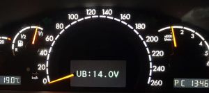 |
Start the vehicle. After few seconds the voltage display will disappear. However, you can locate it again using steering wheel buttons. The voltage reading with the vehicle running should be displayed.
Correct voltage measurement on alternator should be around 14V (or 14.5 for a voltage regulator set to 14.5 volts). The voltage value must not fluctuate (see video of faulty alternator below).
Sometimes the problem can be in the circuit to the battery. To test whether the battery actually receives the voltage generated by alternator, use an accurate Digital Volt Meter (DVM) and monitor the alternator output across the battery terminals. It should match voltage displayed on the instrument cluster.
Note: This method is not suitable for testing the voltage of battery, since several consumers activated will cause a non-objective measurement. Battery voltage must be measured without active consumers (i.e. with minimal load) and only across the battery terminals.
Alternatively, the voltage can be read out from climate control hidden menu. Switch on ignition, press and hold REST button in climate control until hidden menu appears. Go to value NR.24 for voltage reading.
Replacing alternator
- Disconnect negative battery cable. This is important to make sure that when disconnecting alternator battery wire (B+) it does not get shorted to chassis.
- Remove serpentine belt.
- Remove oil dipstick to not accidentally break it off (important on M113 engine (S430/S500)).
- Removing alternator bolts. The bolts are Torx 16, but 11mm socket will work fine too.
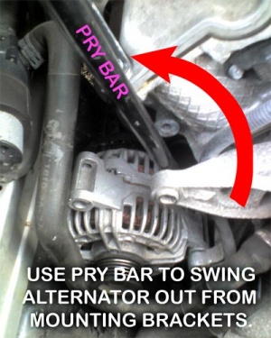
- Tilt alternator out of the bracket. Use pry bar if needed (see below).
- Rotate alternator pulley down (see photo below) and remove wires. Battery wire needs 13mm socket. The other wire pulls of easily.
- Remove alternator from the car. On M112 engine cars (S350) there is a lot of space to do that. On M113 (S430/S500) there is less space, therefore removal will involve some difficulties but is possible without removing engine fan (see photo below).
- Reinstall in opposite order. It will be easier to push the alternator in the lower bracket first. To ease installation, metal washers can be pushed (hammered) out of the bolt holes. Note that the coolant bottom hose bracket is attached with the lower bolt.
 |
 |
 |
 |
Electrical connections
Alternator is connected with two electrical wires:
- The thick B+ wire is permanently connected to battery's positive terminal through 150A fuse in the front prefuse box X4/10.
- The thin blue wire goes to port 15 of right signal acquisition module (SAM). After ignition is switched on 12 volts are supplied from SAM (on S350 only ~1 volt). A small current starts to flow through the line pre-energizing the alternator's field coil. For the alternator to charge, the blue wire must be connected (at least at the beginning to energize it).
If it is problematic to access the connectors through engine bay, the connectors can be attached by accessing alternator from underneath the car.
Replacing alternator voltage regulator
Most of the time failed alternator can be fixed by replacing cheap voltage regulator (i.e., in case brushes are worn). See video below for voltage regulator replacement.
Voltage regulator
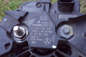
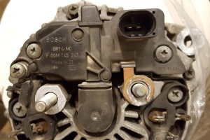
Facelift S350 and S500 comes with factory-fitted BOSCH alternator 0 124 615 012 with voltage regulator F00M 145 247 (BR14-M0) installed.
 |
 |
Compatible part numbers
- Bosch:
- F00M144138
- F00M144152
- F00M145247
- F00M145357
- F00M145339
- Transpo: IB247
- Cargo: 235207
- Lester: 11332
- Mobiletron: VRB247
- HÜCO: 130608 (14.3v)
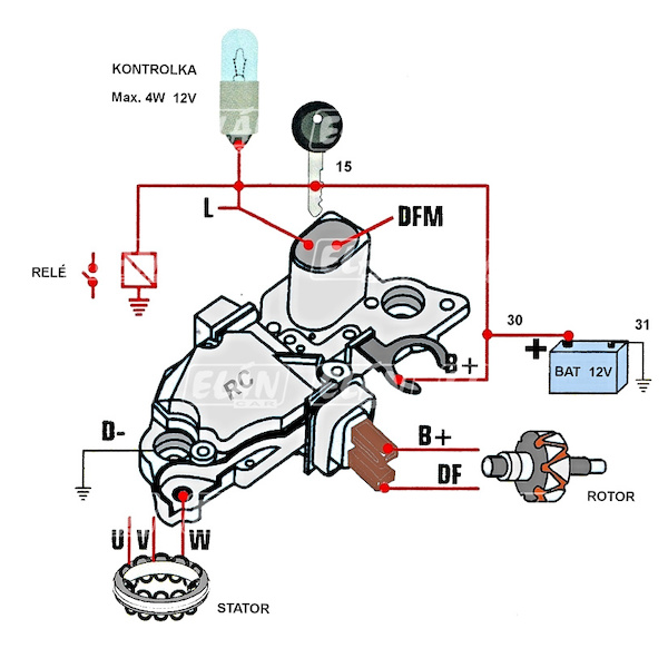
L terminal is tapped to a small voltage through the battery light pre-energizing the field coil (when ignition is on). L provides earth to the battery light through the field coil thereby switching it on (when ignition is on). After the first few revs of the engine a voltage is coming for the alternator side from exciter diodes. This voltage drowns the weak earth through the field coil that was switching the battery light on. Battery light therefore switches of, an indication that the system is charging.
In practice L terminal is not connected to physical warning lamp in instrument cluster, but to port 15 of right signal acquisition module (SAM).
